

Page 1
Technology Data
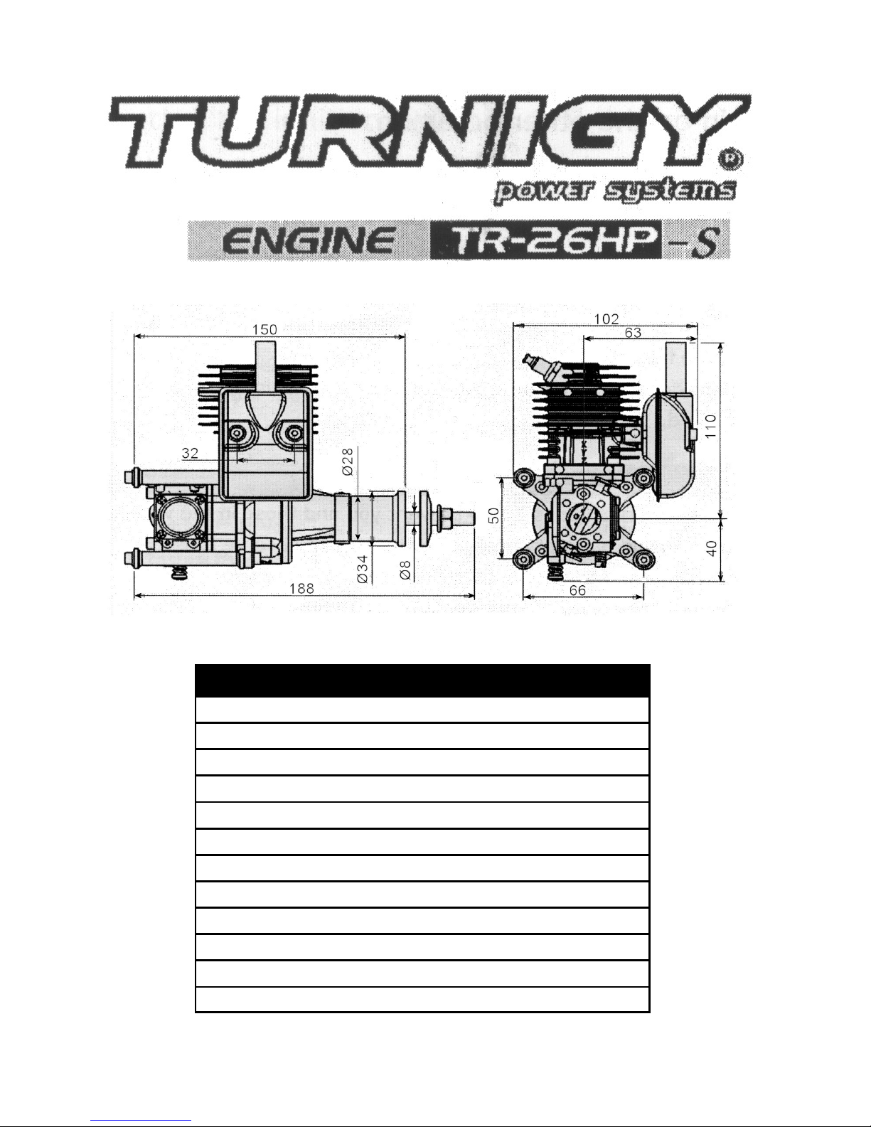
Model: TR-26HP-S
Ignition: DC-CDI (4.8 - 6 V)
Fuel model number: 93# or higher octane value
Cooling: Air cooled
Lubricate Oil: Two Cycle Oil
Mixing Ratio: 25-40 : 1
Max output: 3.0HP
Rpm Range: 1700- 9000 RPM
Spark Plug: NGK CM-6
Propeller: 16xg , 17x8 , 18x8 (Two Blade)
Bore x Stroke: 34 mm x 29 mm
Net Weight: 0.75 kg (Includes Ignition & Muffler)
Page 2

1. This gasoline engine is just designed for the model airplane,
please don't use in on the other occasion.
2. We are obligated to having products which make the defect to
offer the service.
3. Warning! This engine is not a toy! Serious injury and/or death
can occur from its misuse! Read and become familiar with this
entire instruction manual. Learn the engine's applications, limitations, and possible hazards.
4. Modifications or use of the engine for other than its intended
purpose is prohibited.
These safety precautions are to prevent you and those in the
vicinity from incurring harm or damage. Make sure to observe
these precautions and to constantly strive to ensure safety.
Safe use of the engine is your personal obligation and responsibility. Constantly take care to act with good judgment as you
enjoy your hobbies.
1. Have a special designed engine test bench for your engine. If
don't please mounted it on your model aircraft for breaking‑in
2. Mount the engine correctly
3. Provide adequate air flow and cooling for the engine
4. Provide adequate air flow and cooling for the exhaust
5. Use an approved propeller and spinner
6. Balance the propeller correctly
7. Tighten the propeller bolts correctly and check them regularly
8. Properly mount your ignition to avoid overheating
WARNING
SAFETY PRECAUTIONS
Page 3

9. Use the correct battery and regulator (if applicable) for your
ignition
10. Use the correct switch for your ignition
11. Use an appropriate fuel tank, plumbing lines, and installation
12. Use the appropriate fuel for break in and after break in (gas
and oil)
13. Insure adequate filtering of your fuel
14. Maintain your engine properly, keeping it clean, etc.
15. Use a pre‑flight check list before flying your model
16. Secure your model properly when starting
17. Adjust your carburetor correctly
18. Insure that your spark plug is in good condition and is secured
correctly
19. Insure that your ignition wires are not frayed and are protected
20. Insure that your ignition cap is securely mounted
21. Keep all people behind the line of the propeller
22. Do not put anything (i.e., fingers, body parts, objects, et al) into
the rotating propeller
23. Keep children away. All spectators should be kept a safe
distance away from the running engine.
24. Wear proper apparel. Do not wear loose clothing, gloves,
necktie, jewelry, or neck straps for your radio which may get
caught in the moving propeller.
25. Always wear eye protection when starting the engine.
26. Do not operate this engine if you are under the influence of
any drugs, alcohol or medication that could affect your ability to
use the engine properly.
Page 4

1. Make sure to install the power switch.
2. Push the spark plugs cap all the way over the spark plugs (use
gloves)
3. Fixate the unit within the fuselage far away from the receiver by
cable ties.
For gasoline, please use either regular or high octane, for cars.
(the octane number should be 93 or higher).
For oil, use a high‑performing mixed lubrication type of 2‑cycle
engine oil (FB grade or ISO EGC grade) and make the fuel
volume ratio 1(oil) to 25‑40(gasoline).
For fuel piping. Do not use a silicon tube. Clip the weight so that it
does not come off when the engine is running.
1. Fuel tank capacity of 300‑400cc
2. Carburetor
3. Weight
4. Filter mesh, 300 or more
5. Fuel pipe gasoline‑resistant rubber or vinyl tube type with inner
diameter of 2.5‑3mm
6. Fuel pipe gasoline‑resistant rubber tube
7. Air vent pipe
8. Fuel head 100mm or less
Please determine the propeller to use in keeping with the
airplane's size, gross weight. And flight characteristics. If
necessary, consult with someone who has the proper
experience.
IGNITION UNIT MOUNTING
FUEL AND PIPING
ITEMS TO CONFIRM BEFORE STARTING THE ENGINE
Page 5

Fuel pump for gasoline
Electric starter device
Make sure that during the fueling process. The fuel does not
come in contact with the battery or the fuel that has overflowed
does not come in contact with the muffler.
Make sure there is no loosening off or abnormalities with the
tightening, etc., of each part of the engine and model.
Are there any problems with the linkage (in terms of its direction
and actuation stroke)?
Has the battery been sufficiently charged?
Are there any propeller abnormalities (scratches, deformation .
etc)
Re‑tighten the muffler (for starting an engine from the second
try on).
Make sure that the fuel pipe and the wiring of the DC ignition
unit and the like do not pass through the engine's muffler body
and that the wiring and fuel pipe are not interferences.
Starting the engine By Starter
Close the choke lever and open the throttle valve 10%to 15%.
Pressing the tip of the starter to the engine's spinner. Press the
start switch for 1‑2 second and let the engine rotating until saw
some fuel flew out from choke .
Switch on your ignition
If the engine has made an explosive sound. Suspend the
starting operation and start by opening the choke lever and
rotating the engine using the starter. (Opening or closing the
choke lever during engine operation is prohibited.)
*If the engine will not start, leave the choke lever in the open
position and
Page 6

rotate the engine by pressing the starter for 1‑2 second. If the
engine still not starts, repeat this operation 2 or 3 times.
(A) Points in starting
During the first start up operation, does the fuel reach the
carburetor? If the fuel reaches the carburetor, the choke should
be open position.
Is the ignition switch on?
If there is absolutely no explosive sound, remove the spark plugs
and check it.
If the spark plugs became wet condition by over choking, dry it
out, open the choke, and restart.
(B) Cautions in starting
One person must restrain the fuselage during the start up
operation. (Thus start up is prohibited).
With the spark plugs removed when using the starter for rotation
or rotating the propeller by hand. Make sure the ignition switch
has been turned off.
Rotation should be left. Confirm the direction of motor rotation in
advance If the engine
(A)ADJUSTING THE IDLING
After engine start up, set the idling at about. Turn the L needle in
(to reduce fuel), and search for the position for the max. Engine
speed from that position, turn the L needle about 1 1/4 circle, set
the idling speed with the idle screw or the transmitter.
(B)ADJUSTING NUMBER OF ROTATIONS AT FULL
THROTTLE
Achieve full throttle slowly. When the engine speed stabilizes,
turn the H needle in and out to locate the position for the max
rpm.
ADJUSTMENTS AFTER ENGINE START UP
Page 7

From the position of the max. engine speed, open the H needle
1¾ , circle (to increase fuel) to make the setting. In general,
consider 100 rpm to be the difference between the max. Engine
speed and the set engine speed. After making the setting, return
to idling. Accelerate rapidly and confirm that there are no
problems with acceleration. If acceleration is poor, open the L
needle an additional I/8th (45 degree) and confirm that
acceleration is smooth. In this case, the idling will be low, so use
the idle screw or transmitter to adjust it.
This engine has had the carburetor set at the standard position
at the time of factory manufacture. Thus, no calibration is normal
necessary. In keeping, if poor acceleration or insufficient speed
at full throttle or the like result, make adjustments in
conformance with the main points of adjustment after engine
start up. However, the idling change depending on the size of
the propeller used, which will make adjustment using the idle
screw or transmitter necessary.
Different from a glow engine, this engine does not require any
special brake in.
After 5‑10 tanks (2‑3 hours), adjust the carburetor's L and H
needles if necessary.
After about 5 hours' running. The max engine speed will be
slightly increased from initial Max speed, owing to the engine
having been conditioned.
Use a high Octane unleaded fuel (98 Octane is ideal) We
suggest starting the break in process of the engine on a test
stand; for approximately one hour. This time should be used to
get familiar with the engine. Do not run the engine at full throttle
for more than ten seconds during this test stand break in. The
reason for this is that you are not getting the normal cooling
effect that you would if the engine was in a model that was flying,
ENGINE BREAK IN
Page 8

Note:
For break‑in a smaller propeller is recommended.
Important:
1.Remember that when the engine running ever person must stay
behind the line of the rotating propeller; never to the side or the
front!
2.The engine needs 12‑20 hours running time for the break in
process to be 100% complete.
Engine Cooling
A proper cooling system is vital for any engine. An air cooled
engine requires an appropriately sized air intake. Also to keep this
air cooling process working the incoming air must be exhausted.
Further, the exhaust air outlet should be four times (4X) the size of
the cool air intake.
Example:
.10 square inches of air intake area would require
.40 square inches of exhaust air outlet area
It is up to you to insure that the air flows freely to, over, and away
from, the hot cylinder(s) and muffler(s). Please refer to Engine
Installation for motor box considerations, and to the following tips
on baffling.
STOPPING THE ENGINE
To stop the engine, either use the transmitter to achieve full closed
throttle or turn the battery switch off. When you have stopped the
engine and not operating the engine, make sure to keep the
battery switch off.
Page 9

Because this engine uses a battery for power supply, the engine’s
continuous running time will depend on battery capacity. Please
refer to the table on the right for guidelines.
To ensure safe use of the engine, make sure of the items specified
the table below.
Scope of Application
This warranty applies only to the engines and parts manufactured
Jinnuo Machinery and sold directly or through by distributors.
Limit of Warranty
This warranty shall apply only to trouble resulting from material
defects and inferior assemblies that Jinnuo Machinery
acknowledges.
Method and Limit of Compensation
1. Repair or replacement through the distributors, etc,
2. Jinnuo Machinery and its distributors shall not provide
compensation for incidental loss to engine purchasers resulting
from trouble.
Terms of Warranty
The term of warranty shall be three (3) months from the date
purchase, within one year from the date of manufacture,
The warranty shall not cover the following, even if occurring
during the term of warranty.
1. Any faults, failures caused from neglect of this OWNER'S
MANUAL for proper operation and maintenance.
2. Dismantled or modified engines and parts.
3. Expendable parts
4. Trouble resulting from submersion in water, from fire or other
natural disasters or calamities,
5. Engines installed with parts are not genuine.
ENGINE RUNNING TIME
MAINTENANCE
WARRANTY
Page 10

PARTS LIST
To order replacement parts for the TR‑26HP‑S, use the order
numbers in the Replacement Parts Lists that follow. Replacement
parts are available only as listed. Replacement parts are not available from Product Support, but can be purchased from hobby
shops or mail order/Internet order firms. If you need assistance
locating a dealer to purchase parts
Page 11

Code
Mode
Code
Item
Amoun
t
1 26S-1 Needle roller Bearing 1
2 26S-2 Needle roller Bearing 1
3 26S-3 Connecting rod 1
4 26S-4 Crank 1
5 26S-5 Semicircular spline 1
6 26S-6 Bearing 1
7 26S-7 Crankcase comp 1
8 26S-8 Steel cable baffle ring 1
9 26S-9 Bearing 1
10 26S-10 Crankshaft nut 1
11 26S-11 Hub washer 1
12 26S-12 Shaft 1
13 26S-13 Hub 1
14 26S-14 Wave washer 1
15 26S-15 Hall support 1
16 26S-16 Bolt 2
17 26S-17 Piston 1
18 26S-18 Piston pin clamping spring 2
19 26S-19 Piston pin 1
20 26S-20 Piston ring 1
21 26S-21 Cylinder gasket 1
22 26S-22 Cylinder 1
23 26S-23 Bolt 4
24 26S-24 Spark plug CM6 1
25 26S-25 Muffler gasket I
Page 12

Features of product:
This CDI is a kind of electronic automatic Advance angle igniters,
which are specially designed for use of gasoline engine in the
model planes. It adopts PLC microprocessor automatic advance
angle control, accurate ignition time can make gasoline engine
fully exert its performance, and effectively prevent engine from
sharking, and have a power polarity prevent
Specification:
Input voltage: DC 4.8v‑6v
Output voltage: ≥ 20KV
Consume Current: ≤ 550Ma
Temperature: ‑20 ~ 85°C
Relative humidity: 80%
CD1 IGNITONG OWNERS’ MANUAL
Code
Mode
Code
Item
Amoun
t
26 26S‑26 Installation package 4
27 26S‑27 Muffler 1
28 26S‑28 Bolt 2
29 26S‑29 Bolt 2
30 26S‑30 Carburetor 1
31 26S‑31 Carburetor gasket 1
32 26S‑32 leaf valve 1
33 26S‑33 leaf valve gasket 1
34 26S‑34 Bolt 4
35 26S‑35 Crankcase comp 1
CD1‑1 CDI‑1 1
Page 13

Introductions for Use:
Caution: If the power voltage is more than 7V, it will destroy the
ignition. If it is larger than 1OV, it will cause explosion.
Please read it carefully in order to make the Ignition running
steady al make gasoline engine fully exert its performance. Also
please following the below to operate it.
To make sure whether the battery power is match or not, and to
insure have enough Current capacity.
Please use resistance Spark Plugs in order to reduce the
electromagnetic interference.
Demand adopting shielding line links the hall parts can better
eliminate electromagnetic interference.
To cause interference please separate high voltage ignition line
and Hall Transducer.
It adopts negative pulse ready to ignite, to make sure Hall,
Transducer please insure to output for the anode, otherwise
lighting firearms doesn't work.
Install Spark Plugs cap exactly and to be made shielding steel
casing and Spark plugs good and secure.
When installing, please pay attention not to install electronic
igniters on engine directly, so as to avoid high temperature
make the ignition doesn't work normally.
The electronic igniter system shall have a distance with the
receiver system in order to prevent a destruction achieved.
Page 14

Malfunction and Elimination
After install the engine doesn't start up.
Please check whether the power supply the joint connecting is
right or not, if not, please connect it correct.
Check whether the voltage is right or not (4V‑6.8V).
Check whether the Hall parts link is right or not.
Check the Hall part outputs polarity.
The rotation is abnormal after start up engine.
Check battery or power supply shall not less than 4v.
Check whether the ignition's automatic advance angle is match
with your engine or not (please contact with after service of our
company).
Engine doesn't work steady
Check the each on‑line connects whether plug‑in is firm or not,
the credibility has already had no short circuit.
Lighting the front line connects whether ground is good or
not. (shield hull and spark to fill and light a front line to shield a
layer whether the contact is good)
Checking the spark fills to insulate whether intact, whether
electrode cleft is normal or not.
Pilots check list
We strongly recommend checking the following agenda for your
own safety before starting!
1. Check the propeller bolts for tightness
2. Check that the spinner is firmly attached
3. Check the propeller for possible damage
4. Check to be sure you have the throttle position at idle
Page 15

5. Check all batteries
6. Check servo functions
7. Check to see that the ignition switch is OFF
8. Check pressure (6‑8 bar) system of retract (if applicable)
9. Check all linkages for play
10. Check your wheels for possible damage and easy running
11. Check the wing mounting for tight fit and proper attachment
12. Check the canopy for tight fit and proper attachment
13. When starting the engine one person (minimum) has to hold
the model
The engine starts after being choked but then stops soon after.
The low needle on the carburetor is probably too lean. Go back to
the recommended settings and adjust your carburetor from there.
This problem may also indicate a dirty carburetor or faulty ignition.
The engine runs rough and is vibrating strongly.
Balance the propeller. Check the ignition timing. Check your
plumbing for air/fuel leaks. Check your spark plug for carbon
and check the spark plug gap. Check the motor mount to be
sure it is rigid. Check to make sure the engine is mounted on a
level surface so that the crankcase free of tension. Check the
engine and propeller bolts.
The engine doesn't reach a normal RPM at full throttle.
Check the carburetor settings. Check to see if the propeller is
too large Verify that you have the correct muffler system.
Check to see if t engine is overheating. Check the ignition timing. Check the spark plug for defect. Verify you have the correct gasoline, oil, and have mixed them with the correct ratio.
TROUBLE SHOOTING PROBLEM
Page 16

 Loading...