

Page 1
用户手册
Digital Proportional radio control system
INSTRUCTION MANUAL
0678
Http://www.tur nigy.com
Page 2

目录
Digital proportional radio control system
1, 简介Introduction..................................................................................................
2, 服务Services.......................................................................................................
3, 特殊标志Special symbols.....................................................................................
4, 安全指导Safety guide.......................................................................................
5, 2.4G系统2.4GHz System Specifications.................................................................
6, 系统特征项System Characteristics.........................................................................
7, 电池充电注意事项Battery Charging Instructions....................... ..............................
8, 系统简介System Overview....................................................................................
9, 发射机参数Transmitter specifications..................................................................
10, 接收机参数Receiver specifications......................................................................
10.01,TGY-APD01 磁感应速度采集模块RPM telemetry (magnetic) module..............
10.02,TGY-APD02 光感应速度采集模块RPM telemetry (optical) module.................
10.03,TGY-ATM01 温度采集模块Temperature acquisition module..........................
10.04,TGY-AVT01 电压采集模块Voltage acquisition module..................................
10.05,TGY-AEV01 i-BUS 串行总线接收机i-bus receiver.........................................
11,接收机与伺服器连接Receiver and servo connections.............................................
11.01, 飞机模型的安装Airplane model installation.................................................
11.02, 直升机模型的安装Helicopter model installation...........................................
12, 接收机操作说明Receiver Operational Instructions.................................................
12.01, 接口说明Port Setup.................................................................................
12.02, 对码Binding Setup...................................................................................
12.03,TGY-AEV01 i-BUS串行总线接收机连接
i-bus Receiver Connection Setup..............................................................
12.04,TGY-APD01 磁感应转速采集模块连接
RPM telemetry (magnetic) module Setup...................................................
12.05,TGY-APD02 光感应转速采集模块连接
RPM telemetry (optical) module Setup......................................................
12.06,TGY-ATM01 温度采集模块连接
Temperature telemetry module Setup.......................................................
12.07,TGY-AVT01 电压采集模块连接
External voltage teleme try module Setup...................................................
13, 遥控器各部件说明Control Parts Descriptions........................................................
14, 摇杆模式调整Stick mode adjustment....................................................................
15, 开机Power On....................................................................................................
15.01 开机异常保护 Boot abnormal protection...................................................
16, 关机Power Off..................................................................................................
16.01 关机异常保护 Shutdown abnormal protection..........................................
17, 开机画面Logo/Information Screen.......................................................................
18, 主菜单Main menu .............................................................................................
19, 顶部状态栏System Status...................................................................................
20, 功能操作General Functions Description.......... ..............................................
21, 通用功能菜单 General Functions Menu................................................................
21.01, 正逆转Reverse .......................................................................................
21.02, 最大舵量End points ................................................................................
21.03, 记忆微调Subtrim ....................................................................................
21.04, 微调Trims ..............................................................................................
21.05, 比率及指数 Scaling Exponentials .............................................................
21.06, 副翼方向混控 Aileron to rudder .................................................................
1
3
3
4
4-6
7
8
8
9
10
10
11
11
11
11
11
12
13
13
14
14
14
15
15
16
16
17
18
19
19
19
19
16
20
21
21
22-24
25
25
25
25
26
26
27
Page 3

21.07, 方向副翼混控 Rudder to Aileron ..............................................................
21.08, 油门曲线Throttle Curve ...........................................................................
21.09, 油门延迟Throttle Delay ...........................................................................
21.10, 收油门 Throttle Down ..............................................................................
21.11,辅助通道Auxillary Channels ....................................................................
21.12, 通道偏移Channels offset .........................................................................
21.13, 功能延迟 Function Delay .........................................................................
21.14, 通道延迟 Channels Delay ........................................................................
21.15, 线性混控Linear mixes ..............................................................................
21.16, 曲线混控Curve Mixes ..............................................................................
21.17, 状态Conditions.......................................................................................
21.18, 状态延迟Conditions Delay....................................................................
21.19, 逻辑开关Logic switches .......................................................................
21.20, 飞机结构Airplane structure ......................................................................
21.21, 定时器Timers..........................................................................................
21.22, 教练模式Trainer Mode ............................................................................
21.23, 显示舵机Display servos ...........................................................................
21.24, 模型Models ......................................................................................
21.25, 接收设置RX Setup ............................................................................
21.26, 系统System ......................................................................................
22, 固定翼机/滑翔机专有程序功能菜单
Airplane/Glider exclusive function menu..............................................................
22.01, 副翼功能Aileron function.........................................................................
22.02, 襟翼功能Flap function.............................................................................
22.03, 扰流板Spoiler function............................................................................
22.04, 升降襟翼 Elevator to Flap ........................................................................
22.05, 油针曲线Tharottle needle .......................................................................
22.06, 蝶形飞Butterfly ......................................................................................
22.07, 升降功能Elevator function.......................................................................
22.08, 方向功能Rudder function.........................................................................
22.09,V型尾翼V-tail..........................................................................................
22.10, 飞机结构 Airplane Structure ...................................................................
23, 直升机专有功能菜单Helicopter exclusive function menu........................................
23.01, 油门保持Throttle Hold .............................................................................
23.02, 油门混控Throttle Mix ..............................................................................
23.03, 螺距曲线Pitch Curve ..............................................................................
23.04, 倾斜盘混控Swashplate Mix .....................................................................
23.05, 结构 Structure ......................................................................................
23.06, 倾斜类型Swashplate type ........................................................................
23.07, 倾斜盘环Swashplate ring ........................................................................
23.08, 定速设定Governor ..................................................................................
23.09, 陀螺仪Gyroscop ....................................................................................
23.10. 直升机悬停微调Hover trim.......................................................................
24, 报警功能说明Warning funtion Overview...............................................................
25, 常见故障说明Troubleshooting guide....................................................................
26, 功能逻辑关系Function Trees..........................................................................
27, 包装内容Package Contents.................................................................................
28,FCC声明FCC Statement of Compliance...............................................................
2
27
28
28
29
29
30
30
30
31
31
32
32
33
33
34
34
35
35-37
37-38
39-44
45
45
45
46
46
47
47
47
48
48
49
49
49
49
49
50
50
50
51
51
51
52
53
54
56-57
58
59
Http://www.turnigy.com
Page 4
1. 简介 In t r oduction
2. 服务 Se r v ices
如果您使用时遇到任何问题,请参照此说明书。如果您的问题仍然未能解决,请直接联系当地经销商或者我们网站上的客
服人员。
Digital proportional radio control system
3
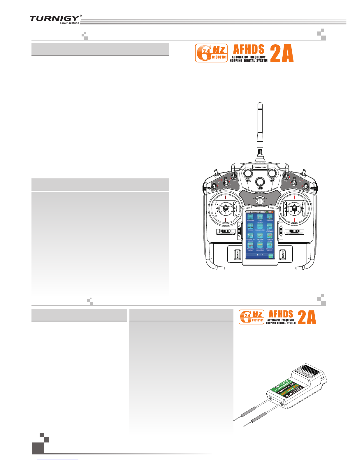
感谢您选择我公司出品的TG Y-i10十通道2. 4G第二代智能遥控系统(AFHDS2A),该系统可10个通道全面兼容直升机、固
定翼、滑翔机,用户按模型结构自行设定。如果这是您第一次使用智能遥控系统,这本使用手册将很快地带给您一个有趣又
高端的全新世界。因此,为了确保您安全使用本产品,请仔细地完整阅读这本使用手册。
Thank you for choosing the TGY-i10 ten channels 2.4 GHz AFHDS2A intelligent system, which is
compatible with helicopter, fixed wing, glider and powered glide systems. System parameters can be set up
based on the model owned by the user. If this is your first time to use an intelligent system, this user manual
will provide you with the instructions you need to obtain full enjoyment from your new system. Before using
your new system, please read all instructions carefully, to ensure your safety.
If you encounter any problems, while using this system, please refer to the appropriate section of this manual. After
consulting this manual, you are unable to solve your problem, please contact your local dealer or connect to consult our service
and support website for further assistance.
Http://www.turnigy.com
Http://www.turnigy.com
Page 5
如果使用者不按照说明方法操作,有可能导致使用者严重受伤,甚至致命的危险。
3. 特殊标志 Special s y m bols
4. 安全指导 Safety gu i d e
请不要在夜晚或者雷雨天使用此产品,因为恶劣的天气环境有可能导致遥控设备失控。
操控时,请先确认模型所有舵机的动作方向与操控方向一致。
如果不一致,请调整好正确的方向。
关闭时,请务必先关闭接收机电源,然后关闭发射机,如果关闭发射机电源时接收机仍然在工作,
将有可能导致遥控设备失控或者引擎继续工作而引发事故。
Mandatory
强制
Prohibited
禁止
当以下标志出现在说明书的时候请注意并且仔细阅读。
如果使用者不按照说明方法操作,有可能导致使用者严重受伤。
如果使用者不按照说明方法操作,有可能导致使用者外伤,甚至严重受伤。
特别要注意,如果附近有汽车正在运行或飞机正在飞行,开机后2.4 GHz R C系统可能会影响到他们。
4
Not following these instructions may expose the user to serious injuries or death.
Not following these instructions may expose the user to serious injuries.
Not following these instructions may expose the user to minor injuries and even to
serious injuries.
Please pay attention to the following symbols when they appear in the manual and read carefully.
Do not use at night or during a lightening storm, as bad weather will adversely affect the control of your system.
Make sure that the motors are all moving the same direction as the operating direction.
The shutdown sequence is as follows: 1. Disconnect the receiver battery 2. Switch off the transmitter Failure to
follow this procedure may result in uncontrolled movement and damage to the system.
Please be aware, that the 2.4G R/C system may affect nearby planes or cars after you turn on the transmitter
Http://www.turnigy.com
Page 6
一定要启用防失控功能。
总是在操作模型之前进行全面的检查。
无线电控制系统出现问题以及不正确安,都有可能导致模型失控,
简单的距离测试方法:
一个人把持模型另一个人持发射机走开,检查该伺服系统运转情况。
测试时要注意到若有异常出现,请不要操作模型。
也检查模型的记忆,以确保模型的匹配是适当的。
不要在户外雨天,有水的地方或当能见度有限的时候使用。
可能水分(水或雪)会进入到系统内部,不稳定的运行和失控可能发生。
不要操作在以下的地方:
基站附近或其他无线电活跃的地方,
人多的地方或道路附近,
有客船的水域,
高压电线或通信广播天线附近,
干扰可能导致失控,
安装不正确,无线电控制系统可能导致模型发生严重的伤害。
当你感到疲倦,饮酒或吸毒后,不舒服的影响下,不要操作这个R / C系统。
判断力下降,而且可能发生危险的情况下,对自己或他人可能造成严重的伤害。
当模型操作或使用后,请勿触摸发动机、电机、定速设定或任何可能发热的部分,
这些部分可能非常热,会造成严重的烧伤。
开机时,每次都要检查发射器的油门中位是否是最低。
当发射机作出调整时,可能模型的引擎没有运行或电机没有连接,可能会发生失控或意外事故的情况。
Digital proportional radio control system
5
Be sure to set the Fail Safe function.
Do not operate outdoors on rainy days, run through puddles of water or use when visibility is limited.
Should any type of moisture (water or snow) enter any component of the system, erratic operation and
loss of control may occur.
Do not operate in the following places:
Near other sites where other radio control activity may occur,
Near people or roads,
On any pond when passenger boats are present,
Near high voltage power lines or communication broadcasting antennas.
Interference could cause loss of control,
Improper installation of your Radio Control System in your model could result in serious injury.
Do not operate this R/C system when you are tired, not feeling well or under the influence of alcohol or drugs.
Your judgment is impaired and could result in a dangerous situation that may cause serious injury to yourself
as well as others.
Do not touch the engine, motor, speed control or any part of the model that will generate heat while the
model is operating or immediately after its use.These parts may be very hot and can cause serious burns.
Please have an overall check about the model before any operation.
Any problem in radio control system or improper installation may cause out of control.
Simple distance test methods:
One hold the model, and the other one carry the transmitter to a proper place to check the servo system condition.
Please stop operation if any exceptional case occurs.
Please check the model memory to make sure the matching is right.
Turn on the power, please check if the throttle neutral position is in its lowest position while turning on the
transmitter every time.
When making adjustments to the model, do so with the engine not running or the motor disconnected, you may
unexpectedly lose control and create a dangerous situation.
Page 7
模型保管:
1. 不要把无线电系统或模型放在幼童伸手可及的地方。
幼童可能会不小心操作系统,这可能发生危险的情况,造成伤害。
2. 不要储存你的R / C系统在以下的地方:
极热或冷的地方,
直接暴露于强光下,
在高湿度环境,
振动频繁的地方,
灰尘多的地方,
在潮湿或者过于寒冷的地方,
存储你的R / C系统在不利条件下,可能会导致变形和许多操作问题。
防失控功能;
检查操作步骤如下:
(1) 打开发射机和接收机,启动发射机防失控功能,并设定在正确的位置。
(2) 至少等待30秒钟,然后关掉发射机电源开关。(发射机每5秒会自动发送防失控的数据到接收机)。
(3) 检查在无接收时,接收机会不会使伺服系统处于预定的位置。
这个功能是一个安全功能,接收失败时,预置伺服系统到预定位置,可以最大限度地减少伤害。
然而,如果设置为一个不当的位置,会有相反的效果,必须重置伺服系统操作的位置。(详情见失控保护功能设
定P37)
电池:
(1) 不要短路电池两极。
(2 )不要把电池放置在有强烈冲击和振动的地方。电池可能会发生短路或过热,电解液
泄漏出来,可能引起烧伤或化学损坏。
6
注意:
请勿放置在燃料,电动机喷雾,废油或排气旁边。燃料,电动机喷雾,废油和排气将渗透和损害塑料。
Battery :
(1) Do not make the battery short circuit.
(2) Do not drop the battery or expose it to strong shocks or vibrations. The battery may short circuit
and overheat, electrolyte may leak out and cause burns or chemical damage.
Storage:
1. Do not leave the radio system or models within the reach of small children.
A small child may accidentally operate the system. This could cause a dangerous situation and injuries.
2. Do not store your R/C system in the following places.
Where it is extremely hot or cold,
Where the system will be exposed to direct sunlight,
Where the humidity is high,
Where vibration is prevalent,
Where dust is prevalent,
Where the system would be exposed to steam and condensation,
Storing your R/C system under adverse conditions could cause deformation and numerous problems
with operation.
Notice:
Do not expose plastic parts to fuel, motor spray, waste oil or exhaust. The fuel, motor spray,
waste oil and exhaust will penetrate and damage the plastic.
Fail safe function:
Before running (cruis in g) , check the fail safe functio n:
Check Method; Before st ar ti ng the engine, check the fail s af e function as follows:
(1) Turn on the transmitte r an d re ceiver power switches.
(2) Wai t at l east 30 seconds, then tur n off the transmitter. ( Th e tr ansmitter automatical ly t ra nsfers the fail
safe data to the receiver e ve ry 5 s econds.)
(3) Check if the fail safe fu nc ti on moves the servos to the pr es et p osition when reception fa il s.
The fail safe f un ct ion is a safety feature that mi ni mi zes set damage by moving th e se rv os to a preset
position when recepti on f ai ls. However, if set to a dangero us p os ition, it has the opposit e effect.
When the reverse functi on w as u sed to change the operating d ir ec tion of a servo, the fail saf e fu nc tion
must be reset.(for more i nf or mation about this funct io n pl ease reference page 37)
Http://www.turnigy.com
Page 8
5. 2.4G系统 2. 4 G Hz System Speci f i c ations
参数说明:
频率范围: 2.4055-2.475GHz
波段宽度: 500KHz
波段个数: 140个
发射功率: 不高于20dBm(100mW)
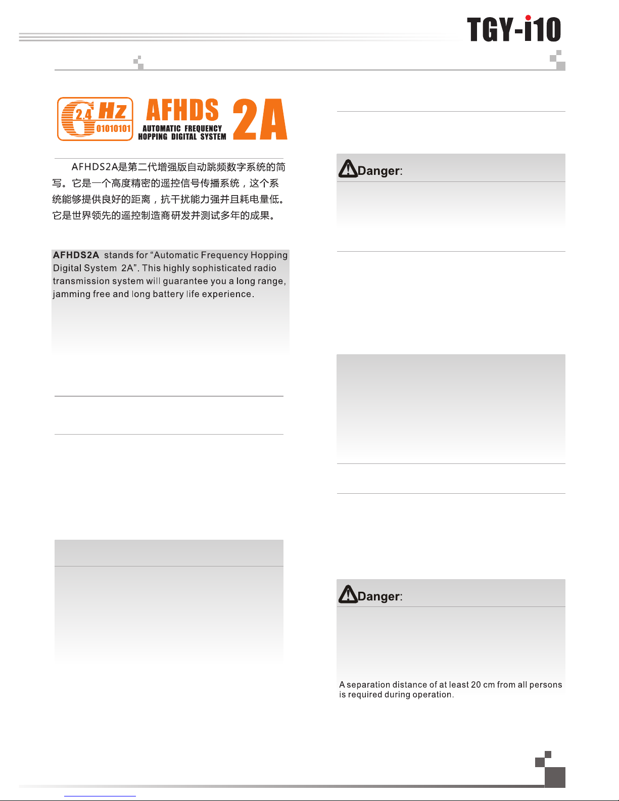
发射模式: AFHDS2A (第二代自动跳频率数字系统)
编码方式: GFSK
天线长度: 26mm ( 双天线)
接收机灵敏度: -1 05dBm
警告!
错误使用遥控设备将可能导致严重的伤害甚至死亡。
请在使用前完整阅读这本使用手册,并且在使用过程中
严格按照此手册的说明操作。
该2.4G无线电波段完全不同于之前所使用的低频无
线电波段。使用时要保持您的模型产品飞行在您的视线
范围内,因为大的障碍物将会阻断无线电频率信号从而
导致遥控失控和危险。2 .4G无线电频率信号是沿直线传
播的,它不能绕过障碍物进行传播。在使用过程中,严
禁紧握发射机天线,否则将会大大减弱无线电传播信号
的质量和强度, 导致遥控设备失控和危险。
警告!
每次使用时,必须先打开发射机,然后再给接收机
通电。停止使用时,必须先断开接收机电源,然后再关
闭发射机。这样操作可以避免接收机接收到错误信号而
导致的伺服器无规律的抖动。这对于电动模型来说尤为
重要, 因为它有可能导致马达突然转动而致使人员伤亡。
20多人一起操作的时候 间距至少要 CM以上。
Digital proportional radio control system
7
Misuse of this radio system can lead to serious
injuries or death. Please read completely this manual
and only operate your radio system according to it.
RF specifications:
RF range: 2.4055-2.475GHz
Channel bandwidth: 500KHz
Number of channels: 140
RF power: less than 20dBm (100mW)
RF mode: AFHDS 2A(Automatic Frequency Hopping
Digital System2)
Modulation type: GFSK
Antenna length: 26mmx2
RX sensitivity: -105dBm
The 2.4 GHz radio band has a completely different
behavior than previously used lower frequency bands.
Always keep your model in sight as a large object can
block the RF signal and lead to loss of control and create
a dangerous situation. The 2.4 GHz RF signal propagates
in a straight line and cannot circumvent objects in its
path. Never grip the antenna during operation as it sig
-nificantly degrades the signal and may cause loss of
control and damage to the system.
Always turn on the transmitter first then the receiver.
When turning off the system, always turn off there ceiver
first then the transmitter. This is to avoid having the
receiver on itself as it may pick a wrong signal and lead
to erratic servo movements. This is particularly important
for electric powered models as it may unexpectedly turn
on the motor and lead to injuries or death.
This
system is developed by th e wo rd 's leading
manufacturer and has be en t es ted for many years.
Page 9
7. 电池充电注意事项 Bat t e ry charging inst r u ctions
如果您的发射机或者接收机使用任何种类
的可充电电池,请在每次飞行前检查电池,确
保电池完好无损并且满电,否则有可能导致失
控或者人员伤亡。
6. 系统特征 System ch a r acteristics
此系统工作频率范围是2 .4055到2.475GHz。整个波段被分为140个独立频点。每套遥控系统使用16个
不同频点和160种不同的跳频算法。通过开机时间不同,跳频规律不同和使用不同的频点,遥控系统能避免
干扰传播信号。
此系统采用高质量的增益天线,覆盖整个波段带宽。配合高灵敏度接收机,系统能有效的避免远距离传
播信号的干扰。
每台发射机有一个唯一的ID码, 当和接收机对码之后, 接收机保存这个唯一的ID码并且只接受从这个ID码
发射机发出的信号。 这样可以避免接收到别的发射机信号,大大增强抗干扰能力和安全性。
此系统使用低功率电子元件和高灵敏度接收机芯片。无线电频率模块采用间歇性信号传播,因此大大降
低了发射功率。比较而言,此系统功耗仅为FM版本的十分之一。
此系统采用信息回传功能,此功能更好的掌握当前模型的工作状态。从而增添了操控乐趣以及更加安全
控制模型。
This radio system works in the frequency range of 2.4055 to 2.475GHz. This band has been divided into
1420independent channels. Each radio system uses 16 different channels and 160 different types of hopping
algorithm. By using various switch-on times, hopping scheme and channel frequencies, the system can
guarantee a jamming free radio transmission.
This radio system uses a high gain and high quality multi directional antenna. It covers the whole frequency
band. Associated with a high sensitivity receiver, this radio system guarantees a jamming free long range radio
transmission.
Each transmitter has a unique ID. When binding with a receiver, the receiver saves that unique ID and only
accept data from that unique transmitter. This prevents obtaining the wrong signal from another transmitter and
insures safety for your system..
This radio system uses low power electronic components and a very sensitive receiver chip. The RF
modulation uses intermittent signal transmission thus reducing even more power consumption. Comparatively,
this radio system uses only a tenth of the power of a standard FM system.
This system uses the two-way communication, which could control the working state of current model better
and make the operation more enjoyable and safer than before.
If your transmitter or receiver uses any type
of rechargeable batteries, please check them
before each flight and make sure they are in
good shape and fully charged other wise it may
lead to loss of control, injuries and death.
如果您使用的是可充电电池,请确保充电器
符合可充电电池规格并且用适当的电流进行充电
否则将导致电池过热,失火甚至爆炸。充满电后,
请立即断开充电电源。如果长时间不用遥控设备,
请将电池从发射机和模型中取出保存,以免有损
遥控设备。
If you are using rechargeable batteries,
make sure to use a suitable charger with the
right charging current set otherwise it may lead
to battery overheating, fire or explosion.
Disconnect the battery from the charger as soon
as it is fully charged. If you don’t planto use
your radio system for a long periodof time,
remove the batteries from thetransmitter and
the model as it may damagethem.
8
Http://www.turnigy.com
Page 10
Digital proportional radio control system
9
· 采用最新双向遥测系统,并可兼容TGY所有单双向接收机;
· 主页面可实时监控i 10电压,模型速度、温度、电压参数,已开启/关闭的功能,模型结构及计时器;
· 系统异常时,弧形动感L ED及3D音效将及时提示;
· 3.55英寸WQVGA TFT 240*400像素触控彩屏可快速、方便的设定参数;
· 防止误操作电源开关设计,左右P OW ER键需同时按方可对i1 0进行开关机;
· 8个开关,5个旋钮在大多数应用中可以指定不同的功能,其中3个旋钮可按压隐藏;
· 高精度双轴承细腻摇杆,超薄轻盈时尚机身设计,给用户一种新的体验;
· 双天线结构让2 .4G频率调信号在各方向传播顺畅,信号安全性更强;
· 可存储20组模型,兼容SD卡并可与之交换数据;可寄存每组模型接收机的对码状态及模型参数.
· 免费软件在线升级,便捷又简单的方式更新系统。
8. 系统简介 System Ov e r view
· 通用功能 (General functions)
正逆转Reverse 、最大舵量End points、记忆微调Subtrim 、微调Trims 、指数Exponentials 、
副翼方向Aileron to rudder 、方向副翼 Rudder to aileron 、油门曲线Throttle curve 、油门延迟Throttle delay 、
收油门Throttle down 、辅助通道Auxiliary channels 、通道偏移Channels offset 、功能延迟Function delay 、
通道延迟Channels delay 、线性混控Linear mixes 、曲线混控Curve mixes 、状态Conditions 、
逻辑开关Logic switches 、飞机结构Airplane structure 、定时器Timers 、教练模式Trainer mode 、
显示舵机Display servos 、模型Models 、接收机设置RX setup 、系统System
· 固定翼/滑翔机 (A irplane/Glider)
默认结构(引擎+副翼+升降+方向)Default structure (Engine+Aileron+Elevator+Rudder)
专有程序Exclusive function menu:
副翼功能Aileron function 、襟翼功能Flap function 、扰流板Spoiler function 、升降襟翼Elevator to flap 、
油针曲线Throttle needle 、蝶形飞Butterfly 、升降功能Elevator function 、方向功能Rudder function 、
V型尾翼V tail
· 直升机(Helicopter)
默认结构(固定螺距)Default structure (fixed pitch)
专有程序Exclusive function menu:
油门保持Throttle hold 、油门混控Throttle mix 、螺距曲线Pitch curve 、倾斜盘Swashplate mix 、
倾斜盘类型Swashplate type 、倾斜盘环Swashplate ring 、定速设定Governor 、陀螺仪Gyroscope
· 兼容直升机、固定翼、滑翔机,分为固定翼/滑翔机、直升机两种飞机类型,不同飞机结构匹配专有程序菜单、
用户按模型结构自行设定:
The transmitter i10:
· Adopts the latest two-way communication systems to ensure that all of the TGY-brand receivers are compatible with this transmitter
· Home page menu can monitor i10 voltage, speed, temperature, voltage parameters, function conditions (on/off), model structure
and timers in real time.
· The flashing LED and 3D audio effect will alert the user when a system exception occurs.
· This parameter is easily set due to the 3.55 inch, 240 by 400 pixels (WQVGA) color TFT-LCD touch screen.
· The power switch design prevents accidental power off or power on conditions. The transmitter can only be turned on/off by
pushing both the left and right power buttons at the same time.
· Eight switches and five knobs can be assigned to different functions in most applications. The three knobs can be hidden by
pressing them.
· The high-precision double-bearing gimbal and fashionable ultra-thin transmitter ensure a great experience for the user.
· The double antenna structure ensures the 2.4G frequency module transmits in all directions for a safer and better signal.
· The transmitter can store 20 models, including every model binding conditions. It can also store model settings on a SD card.
· Free software and upgrades to the system are available online.
·It is compatible with helicopter fixed-wing, glider, and powered glider. Airplane has two type, fixed-wing and helicopter.
Different airplane structure is matching with different procedure. Users can set according to airplane structure.
Page 11
9. 发射机参数 Tra n s mitter specifi c a tions
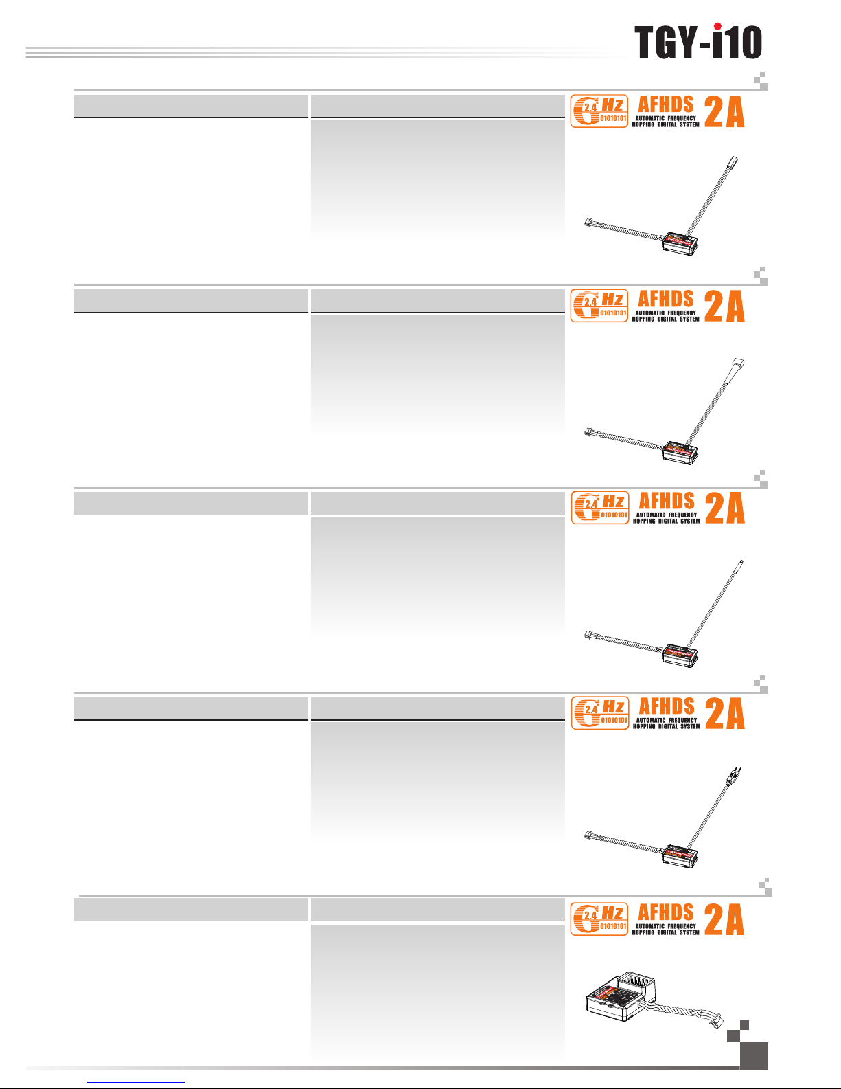
10. 接收机参数 Rec e i ver specificat i o ns
机种参数:
通道个数:10
适合机种: 直升机、固定翼、滑翔机
频率范围:2.4055-2.475GHz
波段宽度: 500KHz
波段个数: 140个
发射功率: 不高于20dBm
2.4G模式: 第二代增强版自动跳频数字系统
编码方式: GFSK
通道分辨率: 1 024级
低电压报警: 有(低于3.75伏时)
数据输出: 有(U SB,HID)
SD卡接口: 有
天线长度: 26mm(双天线)
机身重量: 653.5g(含电池)
输入电源: 3.7伏(800毫安时)
外形尺寸:278.59mm*189.35mm*95.87 mm
外观颜色: 银色
认证: CE0678,FCC
.
.
.
.
.
.
.
.
.
.
.
.
.
.
.
.
.
.
机种参数:
通道个数: 10
适合机种: 直升机、固定翼、滑翔机
频率范围: 2.4055-2.475GHz
波段个数: 140个
发射功率: 不高于20dBm
接收灵敏度:-105DBm
2.4G: 第二代增强版自动跳频数字系统
编码方式: GFSK
天线长度: 26mm(双天线)
输入电源: 4.0-6.5V/DC
机身重量:19g
外形尺寸:47mm*33.5mm*15mm
外观颜色: 黑色
认证: CE0678,FCC
i-BUS 接口: 有
数据采集接口: 有
.
.
.
.
.
.
.
.
.
.
.
.
.
.
.
.
Channels: 10
Model type: helicopter/ airplane/ glider
RF range: 2.4055-2.475GHz
Bandwidth: 500KHz
Band: 140
RF power: less than 20 dBm
2.4G system: AFHDS2A
Code type: GFSK
Sensitivity: 1024
Low voltage warning: yes (less than 3.75V)
DSC port: yes(USB, HID)
SD port: yes
ANT length: 26mmx2
Weight: 653.5g (Include Battary)
Power: 3.7V (800mAh)
Size: 278.59mm*189.35mm*95.87mm
Color: Silver
Certificate: CE0678, FCC
.
.
.
.
.
.
.
.
.
.
.
.
.
.
.
.
.
.
Transmitter specifications:
Channels: 10
Model type: helicopter/ airplane/ glider
RF range: 2.4055-2.475GHz
Band: 140
RF power: less than 20 dBm
Sensitivity: -105DBm
2.4G system: AFHDS2A
Code type: GFSK
ANT length: 26mmx2
Power: 4.0-6.5V/DC
Weight: 19g
Size: 47mm*33.5mm*15mm
Color: Black
Certificate: CE0678, FCC
i-BUS Port: yes
Date Acquisition port: yes
Specifications:
.
.
.
.
.
.
.
.
.
.
.
.
.
.
.
.
MODEL:TGY-iA10
10
Http://www.turnigy.com
MODEL:TGY-i10
Page 12
10. 0 1. 磁感应速度采集模块 RPM T ele metr y (ma g net ic) mo dul e
适合机种: i系列
采集速度范围: 0-16000转/分钟
机身重量: 3.9g
输入电源: 4.0-6.5V/DC
外形尺寸: 24.4*14*8毫米
外观颜色: 黑色
10. 0 3. 温度采集模块 Te mpe ratu re te l eme try mo dul e
MODEL: TGY-ATM01
适合机种: i系列
采集温度范围:-4 0-100摄氏度
机身重量: 3.9克
输入电源: 4.0-6.5V/DC
外形尺寸: 24.4*14*8毫米
外观颜色: 黑色
适合机种: i系列
电压采集范围: 4.0-30V/DC
机身重量: 3.9克
输入电源: 4.0-6.5V/DC
外形尺寸: 24.4*14*8毫米
外观颜色: 黑色
10. 0 4. 电压采集模块 Vol tage t ele metr y mod u le
MODEL: TGY-AVT01
通道个数:4
适合机种: i系列
机身重量: 6.7克
输入电源: 4.0-6.5V/DC
外形尺寸: 30*25.6*13毫米
外观颜色: 黑色
i-BUS 接口: 有
10. 0 5. i- BUS 串行总线接收机 i -bu s rece iver
MODEL: TGY-AEV01
MODEL: TGY-APD02
适合机种: i系列
采集速度范围: 0-16000转/分钟
机身重量: 3.9g
输入电源: 4.0-6.5V/DC
外形尺寸: 24.4*14*8毫米
外观颜色: 黑色
10. 0 2. 光感应速度采集模块 RPM T ele metr y (op t ica l) mod ule
MODEL: TGY-APD01
Digital proportional radio control system
511
机种参数:
机种参数:
机种参数:
机种参数:
机种参数:
Model type: helicopter/ airplane/ glider
Monitor range of speed: 0-16000RPM
Weight: 3.9g
Power: 4.0-6.5V/DC
Size: 24.4*14*8mm
Color: Black
Specifications:
Model type: helicopter/ airplane/ glider
Monitor range of speed: 0-16000RPM
Weight: 3.9g
Power: 4.0-6.5V/DC
Size: 24.4*14*8mm
Color: Black
Model type: helicopter/ airplane/ glider
Monitor range of temperature: -40-100°C
Weight: 3.9g
Power: 4.0-6.5V/DC
Size: 24.4*14*8mm
Color: Black
Model type: helicopter/ airplane/ glider
Monitor range of Volatge: 4.0-30V/DC
Weight: 3.9g
Power: 4.0-6.5V/DC
Size: 24.4*14*8mm
Color: Black
Channels: 4
Model type: helicopter/ airplane/ glider
Weight: 6.7g
Power: 4.0-6.5V/DC
Size: 30*25.6*13mm
Color: Black
i-BUS Port: yes
.
.
.
.
.
.
.
.
.
.
.
.
.
.
.
.
.
.
.
.
.
.
.
.
.
.
.
.
.
.
.
.
.
.
.
.
.
.
.
.
.
.
.
.
.
.
.
.
.
.
.
.
.
.
.
.
.
.
.
.
.
.
Specifications:
Specifications:
Specifications:
Specifications:
Page 13
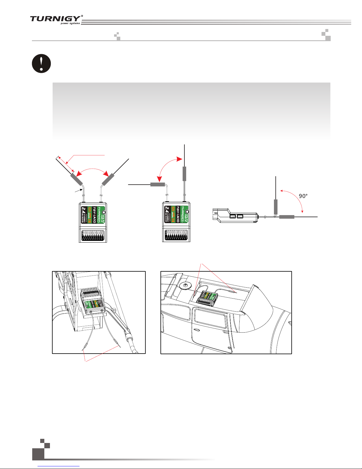
11. 接收机与伺服器连接 R e ceiver and serv o c o nnections
为了让发射及接收距离更远,请注意以下几点:
1、尽量保证双天线笔直,否则将会减小控制范围;
2、双天线的夹角保持在9 0°(如图三种方式), 这并不是精确的垂直角度,重要的是尽可能保持天线互相远离;
3、天线应该尽可能远离金属导体,至少要有l. 5c m左右的距离。轴电缆段不受此限制,但不要过度弯曲;
4、尽可能保持天线远离电动机、调速器,和其它的噪声源。
接收机
Receiver
( Pic 11.1 )
( Pic 11.2 )
In order to make sure maximum distance between the transmitter and receive can be obtained please follow the
directions below:
1. The two antennas must be kept as straight as possible. Otherwise, control range will be reduced.
2. The two antennas should be placed at a 90 degree angle to each other, as illustrated in the three pictures below.
3. The antennas must be kept away from conductive materials, such as metal and carbon. A distance of at least 15 cm
is required for safe operation. Conductive materials will not affect the coaxial part of the antenna, but it is important
that the coaxials are not bent to a severe radius.
4. Keep antennas away from the motor, speed controller and other noise souces as much as possible.
天线(26mm)
同轴电缆
9
0°
9
0°
12
天线
天线 Antenna
Antenna
接收机
Receiver
( Pic 11.3 )
接收机
Receiver
Coaxial cable
Http://www.turnigy.com
Page 14
Digital proportional radio control system
13
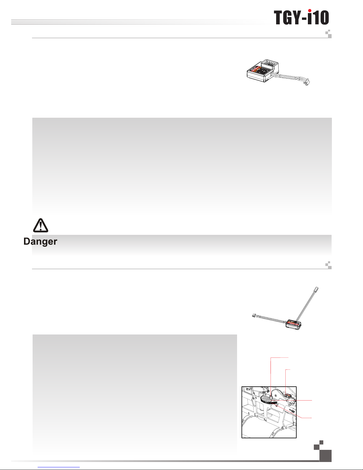
11. 02 直升机模型的安装 H eli c opt er mod el in stal lat i on
CH1
CH2
CH3
CH4
CH5
CH6
CH7
CH8
CH9
CH10
Gyroscope陀螺仪
Pitch 螺距
Governor 定速设定
Needle 油针
Aux.1辅助通道
Aux.2辅助通道
B/V
油门舵机
Throttle servo
方向舵机
Rudder servo
副翼舵机
Aileron servo
升降舵机
Elevator servo
开关
电池
接收机 Receive r
接收机和直升机的连接方法,例如:
结构:可变螺距(120度)+油 门油针+陀螺仪+定速设 定
Ch1:副翼Aileron Ch2:升降Elevator
Ch3:油门Throttle Ch4:方向Rudder
Ch5:陀螺仪Gyroscope Ch6:螺距Pitch
Ch7:定速设定Governor Ch8:油针Needle
CH9:AUX1 CH10:AUX2
Receiver and helicopter connections, for example:
Structure: throttle needle+variable pitch(120 degrees)+ gyroscope+governor
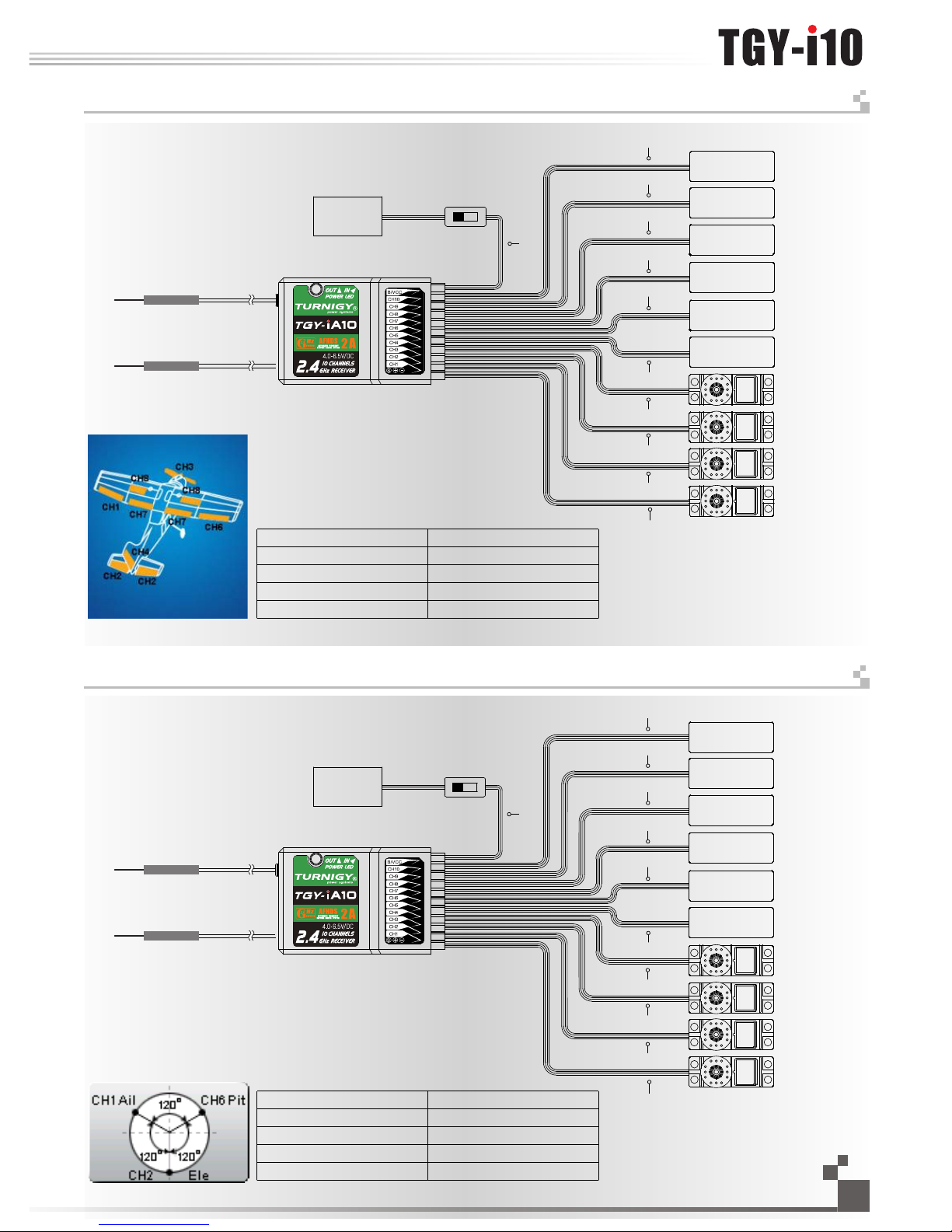
11. 01 飞机模型的安装 Air pla ne mod el in stal lati on
Aux.1辅助通道
Aileron 副翼
Flap 襟翼
Spoiler 扰流板
Aux.2辅助通道
Aux.3辅助通道
接收机 Receiver
CH1
CH2
CH3
CH4
CH5
CH6
CH7
CH8
CH9
CH10
B/V
油门舵机
Throttle servo
方向舵机
Rudder servo
副翼舵机
Alieron servo
升降舵机
Elevator servo
开关 Switch
电池
接收机和固定翼的连接方法,例如:
结构:两个副翼+襟翼+扰流板
Ch1:副翼Aileron Ch2:升降Elevator
Ch3:油门Throttle Ch4:方向Rudder
Ch5:AUX1 Ch6:副翼Aileron
Ch7:襟翼Flap Ch8:扰流板Spoiler
CH9:AUX2 CH10:AUX3
Connection method for the receiver and
the fix wing, for example:
Structure: Two ailerons+flap+spoiler
Battery
Battery
Switch
Page 15
12. 接收机操作说明 Receiver o p e ration instruc t i on
对码线
Bind cable
接收机
Receiver
10
电池
Battery
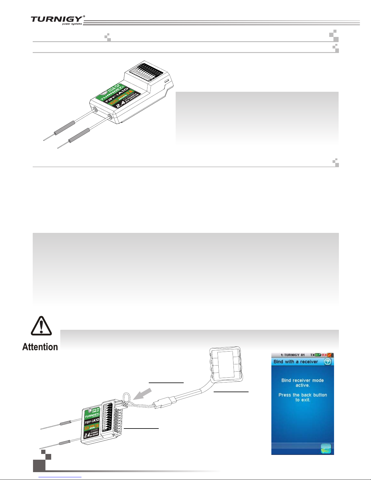
12. 02 对码 B ind ing Se tup
12. 01 接口说明 P ort S etup
所有的发射机和接收机,在出厂前都已对码,无需再次对码,若您需要与另一发射机进行对码和使用,
请按以下方法操作:
1. 发射机装上电池,打开电源;
2. 进入主界面,选择接收机设置功能。点触对码进入对码状态;
3. 用产品包装所配的对码线,插入接收机B /V CC通道;
4. 使用4.0-6.5VDC电源,按正确极性,插入CH1- CH10的任一通道,即可进入对码状态,此时LED灯闪烁;
5. 成功对码后,发射机会自动退出对码状态;
6. 拔掉对码线,重启接收机L ED常亮,此时即可插入舵机及其它数据采集模块,检测其工作是否正常;
7. 如果对码失败,可重复以上动作,重新对码。
(Pic 12.1)
(Pic 12.2)
CH1-CH10: 表示接收机的相应通道;
Bind,VCC: 表示用于对码和输入电源的通道;
OUT:表示输出PPM数据的i-BUS接口,用于连接串行总线接收
机,扩展通道;
IN:表示各种传感器数据的输入接口,数据采集模块可随意串接;
CH1-CH10: represent relevant channel of transmitter.
Bind,VCC: represent the channel used for matching and input
power respectively.
OUT: Represent i-BUS port of outputting PPMS data and be used
for connecting the serial bus receiver to expand channels.
IN: Represent input ports of all kinds of sensor data, and data
acquisition modules can be connected in serial optionally.
All receivers are bound to their respective transmitter at production time. If you want to bind it with another transmitter,
please follow the steps below:
1. Install the battery in the transmitter, and turn on the power.
2. Open the main menu, and select "RX setup" function in the second page, then touch "Bind with a receiver" to enter bind mode.
3. Insert the standard bind cable into the power supply channel.
4. Connect the 6VDC power connector to any channel from CH1 to CH10 with correct polarity to enter bind mode, The receiver
LED will flash at this time.
5. The transmitter will exit the bind mode automatically after having successfully bound with the transmitter.
6. Pull off the bind cable and restart the receiver. Please connect the servos and other telemetry modules to the receiver to check
if everything operates normally.
7. If anything is wrong, please repeat the above steps to bind again.
注意:配对好的发射机与接收机,当发射机或接收机因误操作而进入对码状态后, 会出现不能遥控的现象,
一般情况下,关闭电源重开机即可恢复正常,倘若还是不行,则需要重新对码。
Notice: The bound transmitter and receiver will work abnormally if the transmitter or the receiver enters the binding state
by mistake. In other words, the receiver cannot be controlled by the transmitter. If so, you need to restart the transmitter
and the receiver.
14
Http://www.turnigy.com
Page 16
Digital proportional radio control system
15
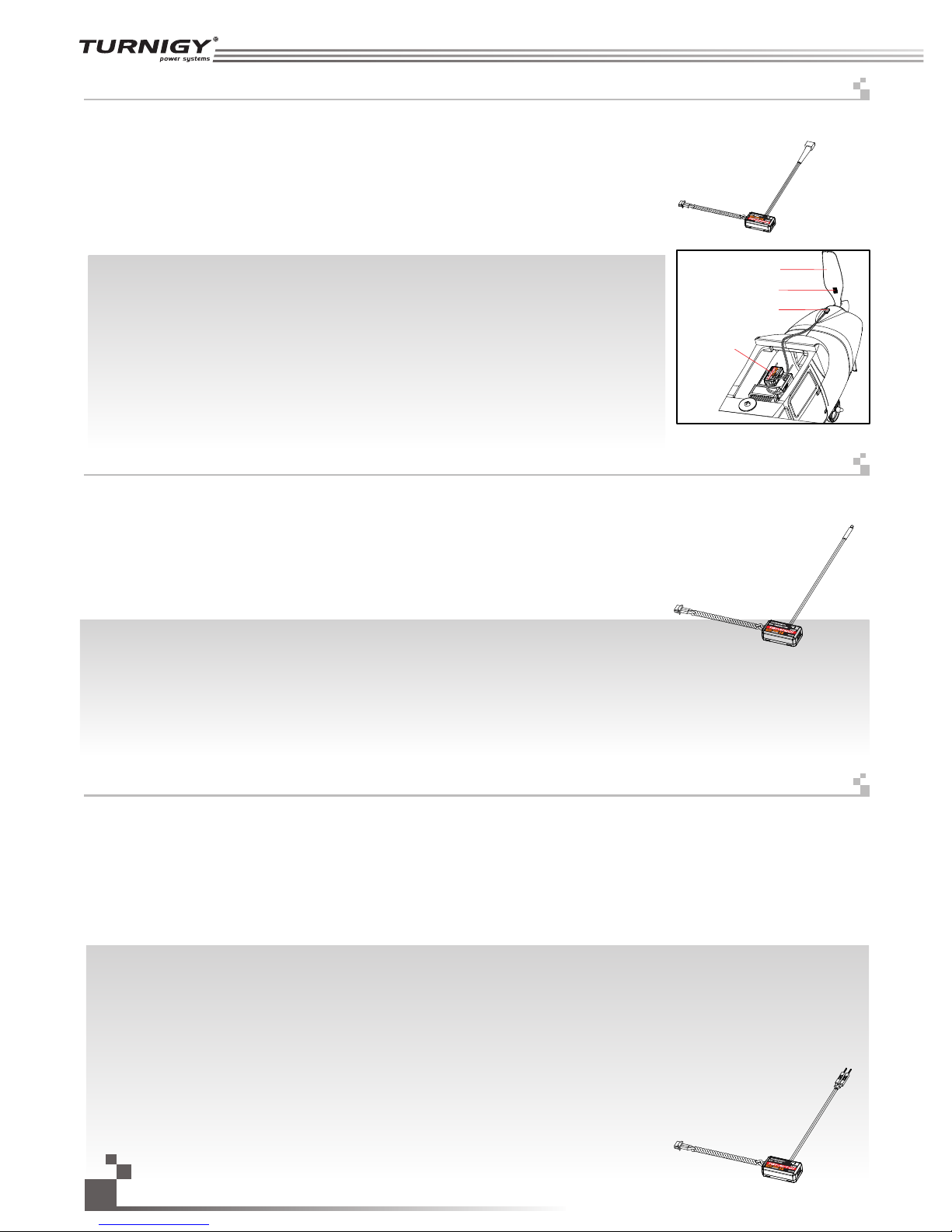
12. 03 TG Y-AE V0 1 i-B US 串行总线接收机连接说明 i- bus Re cei ver Co nne c tio n inst ruc tion S etu p
12. 04 TG Y-A PD0 1 磁感应转速采集模块 RPM t e lem etry ( mag neti c) mo d ule s etup
传感器 Sensor
速度采集模块
Revolving
speed module
齿轮
Gear
磁铁
Magnet
串行总线接收机,最多可串联4个模块,共16个通 道;按键K1-K 4分别对应C1 -C4, 用于 对相应通道的设定;
操作说明:
1.TGY-AEV 01 i-BU S接收机的“I N”端口对应接收机的“OUT” 端口;
2. TGY-AE V01 i-B US接收机的 “OU T”端口,用 于串接后级的FS -SEV0 1接收机,以 串联的 方式使用。
3. 将此总线接收机插入接收 机,打开己配对 的发射机,接收 机电源,LE D点亮;
4. 操作发射机触控屏,选择 接收机设定的主 菜单,进入到舵 机设定界面;
5. 选择需要扩展的通道,此 时,总线接收机 的LED熄灭;
6. 用对码线上的胶针,按下 需要的,相应通 道的按键,LED自动点亮,表 示设定成功;
7. 插入舵机,检查设定是否 成功;
8. 重复以上操作即可完成总 线接收机4个通道的 设定;
9. 当需要更多的通道扩展时 ,只需要在第一 级总线接收机的 “OUT”端口 ,串接新的总线 接收机即可,设定的操作方法相同。
注意: 当总线接收机的负载过重,电流较大时,请将主接收机的电源分支出来并联接入,单独供电加大负载的能力,
否则可能会因电流过大,烧坏串联的线材。
操作使用说明:
1. 将所配的3 PIN插头, 一端插入速度采集模块的“OUT”位置,另一端插入接收机的“IN ”位置或
接另外的感应器的“IN”位 置,如图1 2.4所示;
2. 如图12.5所示,将传感器放在磁铁的旁边,磁铁固定在需要测试的轴向转动的地方 ,如直升机的
齿 轮上面,传感器与磁铁相 距两毫米以内,磁铁的南极或北极 与传感器保持平行。
3. 打开发射机,接收机电 源,在显示屏的接收机窗口内,会发现并显示“Motor speed 2:0RPM”,
试着转动,转速的值会发 生变化,则表示安装成功。
(Pic 12.3)
(Pic 12.4)
(Pic 12.5)
15
i-BUS receiver, can connect 4 modules with 16 channels in serial at most. Button K1 and K4 correspond to C1 and C4
respectively.
Operation instruction:
1.TGY-AEV01 i-BUS The “IN” port of TGY-AEV01 receiver corresponds to “OUT” port of receiver.
2. TGY-AEV01 i-BUS The “OUT” port of TGY-AEVO1 receiver is used to connect post level TGY-AEV01 receiver.
3. Insert the bus receiver to receiver, and then switch on the matched transmitter and receiver. The LED will be on.
4. Select main menu of receiver setup to enter the interface of servo setup.
5. Select channel which need to be expanded, meanwhile LED of bus receiver is off.
6. Push relevant channel button by plastic needle of matching line. The setup is successful if LED flashes automatically.
7. Insert servo to check.
8. Set up 4 channels of bus receiver as above steps.
9. Just connect a new bus receiver with “OUT” port of first stage bus receiver if more channel needed. Set up the new one as
above steps.
Notice: When the load of serial bus receiver is excessive and electric current is higher than usual, please supply power
directly to the serial bus receiver or it will break cables.
Operation:
1. Insert one end of standard 3 PIN plug into “OUT” port of RPM telemetry (magnetic)
module, and insert the other end into “IN” port of receiver or other sensor, as shown
in the picture 12.4.
2. As shown in the picture 12.5: Inside hub of the model, the distance between sensor
and magnet is less than2mm. The North Pole or the south pole of the magnet has
to be paralleled with sensor.
3. Switch on transmitter and receiver. “Motor speed 2:0RPM” will be shown in receiver
window in display screen. Speed value changes as turning wheel, which means
installation is successful.
功能说明:
此功能是为了应对某些模型 通道太多而做的 ,当通道不够时 可采用此配件,来增加通道输出。
功能说明:
此功能是为了检测到模型 的转速而设定的,用户可通过发射 机来观察监测模 型的转速,当用户需 要监测转速时可使用此配件。
After connecting one TGY-AEV01 i-bus receiver to TGY-iA10 receiver, It will allow user to add four more
channels if the channels on the receiver is not sufficient.
This function allows th e us er t o monitor turning speed via t he t ra nsmitter. This i s a
very useful function wh en d et ermination of turning spe ed i s re quired
Function Details:
Function Details:
Page 17
操作使用说明
1. 将所配的3PIN插头,一端插入速度采集模块的“OUT”位置,另一端插入接收 机的 “IN”位置或
接另外的感应器的“IN”位 置,如图1 2.6所示;
2. 如图12.7所示,将 传感器与反射贴纸固定在测试的轴 向转动,如安装在飞机的螺旋桨上,保持贴纸
平整,并与传感器垂直, 传感器和贴纸距离要保持适中。
3. 打开发射机,接收机电 源,在显示屏的接收机窗口内,会发现并显示“Motor sp eed 2:0RPM”,
试着转动,转速的值会发 生变化,则表示安装成功。
操作使用说明:
1. 将所配的3 PIN连接线 ,一端插入温度采集模块的“OUT”位置,另一端插入接收机的“I N”位置或接另外的感应器的“IN”位置,
如图12.8所示;
2. 将温度的传感器本体, 使用海棉双面贴粘在适当的位置(如:马达,电池本体上),并与被测试物表面紧贴;
3. 打开发射机,接收机电 源,在显示屏的接收机窗口内,会发现并显示“Temperat ure 1:25.0℃”,表示安装成功,
25.0℃ 即为采集到的温度数据。
螺旋桨 Propeller
速度采集模块
Optical rotation
speed telemetry
module
16
12. 06 TG Y-AT M01 温度采集模块连接 Temp era t ure t elem etr y modu le co n nec tion s etu p
12. 05 TG Y-AP D0 2 光感应转速采集模块 RPM Te lem e try ( opti cal ) modu le se t up
反射区 Magnet
传感器 Sensor
12. 07 TG Y-AVT 01 电压采集模块连接 Ext erna l vol t age t elem etr y modu le co n nec tion s etu p
操作使用说 明:
1. 将所配的3 P IN连接线, 一端插入电压采集模块的“O UT”位置, 另一端插入 接收机的“IN”位置或接另外 的感应器 的“I N”位置,如图12 .9所示;
2. 打开发射 机,接收机电源,在显示屏的接收机窗 口内,会发 现并显示“Ext .vo ltage 4:0V”,表示安装成 功;
3. 将用于检 测的红黑线插针分别插入电池的插头内 ,红色线为 正极,黑色线为负极,如图1 2.9所示: 在显示屏的 接收机窗口内,显示“Ext .volt age 4:
12.40 V",表示己检测到外部 的电池电压 为:1 2.4 0V。
注意:用于 检测的红黑线, 不能接反, 否则会损坏接收机。
注意: 请不要将采集 模块的"IN"和“O UT”接反, 否则发射机将无法识别到该模块及相连的后面的模块 的编号。
(Pic 12.6)
(Pic 12.7)
(Pic 12.8 )
(Pic 12.9)
1. Insert one end of standard 3 PIN plug into “OUT” port of temperature module, and insert the other end into “IN” port of
receiver or other sensor, as shown in the picture 12.8 .
2. Adhere temperature sensor to proper place (such as motor and battery) tightly by sponge double stick.
3. Switch on transmitter and receiver. “Temperature 1:25.0℃” will be shown in receiver window in display screen, which means
installation is successful, and 25.0℃ is the temperature collected.
1. Insert one end of standard 3 PIN plug into “OUT” port of external voltage module, and insert the other end into “IN” port
of receiver or other sensor, as shown in the picture 12.9.
2. Switch on transmitter and receiver. “Ext.voltage4:12.40V” will be shown in receiver window in display screen, which
means the installation is successful.
3. Insert red and black contact pin into battery port respectively. The red one is positive pole and the black one is
negative pole.as shown in the picture 12.9“Ext.voltage4:12.40V” is shown in the receive widow in display screen,
which means the tested voltage is 12.40V.
Notice: The polarity of red and black line can not be reversed, or the receiver will be damaged.
Notice: Be sure the IN and OUT ports are connected correctly. Improper connections
will cause the transmitter to be unable to distinguish between telemetry modules.
1. Connect one end of the standard 3 PIN plug to the "out" port of the speed telemetry module
and the other end to the "in" port of the receiver or the previous sensors “in” port as shown in
the picture 12.6.
2. As shown in the picture 12.7: Affix the sensor and the reflection decals on the flat surface of
the side of any rotating part. Keep decals flat and perpendicular to the sensor. Maintain
sufficient safety distance between the sensor and the decals to avoid any damage.
3. Switch on the transmitter and the receiver. “Motor speed 2: 0RPM” will be displayed in the
main screen. The speed displayed will follow the speed of the rotating part monitored by the
rotation speed sensor, indicating a successful installation.
功能说明
此功能是为了能检测到模型 的转速而做的, 用户可通过遥控 器来观察和监测模型的转速,当用户需要监 测转速时,可使 用此配件。
功能说明:
此功能是为了监测模型重要 部件(马达,电 池,调速器)温 度而做的,用户可通过遥控 器来观察和监测 重要部件的温度 ,必要时可设定报警。
当用户需要检测重要部件温度时可使用此配 件。
功能说明:
此功能是为了监测模型电池 电压的,用户可 通过遥控器来观察和检测电 池的电压情况, 必要时可进行设定报警。用 户需要观察和监 测电池电
压时可使用此配件。
This function allows th e us er t o monitor turning speed via t he t ra nsmitter. This i s a ve ry
useful function when de te rm ination of turning speed is r eq ui red
This function a ll ow s the user to monitor the tem pe ra ture of important operati ng p ar ts of the system.
This will ensure that the u se r ca n be aware of any severe temper at ur e changes which would adver se ly a ffect
system operation. The system will automati ca ll y set an alarm if the temperatu re i s ou tside of safe operating n or ms
This function a ll ow s the user to monitor the bat te ry v oltage of the system. This will ensure that the user c an b ea ware of
any severe voltage chan ge s wh ich would adversely affect battery operation . The system will autom at -i cally set an alarm if
the voltage is outside of s af e op erating norms
Function Details:
Operation instr uction:
Function Details:
Operation instruction:
Function Details:
Operation instruction:
Http://www.turnigy.com
Page 18
Digital proportional radio control system
17
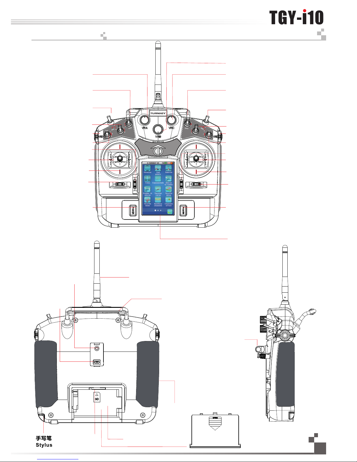
13. 遥控器各部件说明 Cont r o l Parts Descript i o ns
旋钮 VrA
两档开关 SwD
两档开关 SwC
两档开关 SwB
旋钮 VrD
电源开关 Power button
旋钮 VrC
两档复位开关 SwG
旋钮 VrE
三档开关 SwF
旋钮 VrB
升降微调杆 Elevator trim
油门微调杆 Thro trim
USB 接口
USB port
教练接口
Trainer port
电池盒
Battery Box
提手 Handle
挂带环
Hook
天线 Antenna
三档开关 SwA
方向微调杆 Rudder Trim
两档开关 SwH
副翼微调杆 Aileron trim
油门
Thro/升降Elevator
副翼 Aileron
液晶显示屏 LCD
升降 Elevator/油门 Thro
方向 Rudder
握把
卡槽
电池盖
两档开关 SwE
Battery Cover
Grip
SD
SD Card slot
电源开关 Power button
Page 19

18
将发射机默认摇杆模式调整为1、3、4;
步骤如下:
1、点触系统选择摇杆模式,可见摇杆模式默认为模式2 (如图14.1);
2、模式4调整:由模式2切换为模式4即可 (如图14.2);
3、模式1、3调整
1)、切换为模式1或模式3 (如图14.3, 1 4.4);
2)、打开发射机的电池盖,取下电池;
3)、拔下发射机左右握把;
4)、用内六角螺丝刀卸下锁住发射机后盖的6颗螺丝 (如图14.5),并妥善放置;
5)、轻轻地拨下发射机后盖电线插头,即可看到和 (图14. 6) 一样的布局;
6)、用小型十字螺丝刀卸下总成8颗螺丝,并妥善放置;
7)、将左右总成座互换位置 ,排好电线,并锁紧螺丝;旋转180度
8)、将发射机后盖电线插头小心地插入主板,重新合上发射机的后盖,并
锁紧螺丝;
9)、装上左右握把,装入电池,盒上电池盖;
10)、打开发射机点触显示舵机检查通道及方向是否正确,拨动微调杆检查
微调及方向是否正确。
14. 摇杆模式调整 S tick mode adjust m e nt
(Pic 14.1) (Pic14.2)
(Pic 14.3) (Pic 14.4)
The instructions for changing default mode 2 are detailed below:
1. Touch system option to select the stick mode as shown in picture 14.1.
2. Change mode to 4.
3. Adjustment of mode 1 and mode 3 as shown in pictures 14.3 and 14.4
1). Change mode 1 and mode 3 to mode 1 or mode 3.
2). Open the battery box and remove the battery.
3). Remove the transmitters left and right grips.
4). Use the inner hexagonal screwdriver to remove the six screws on the
back of the transmitter and put them in a safe place as shown in
picture 14.5.
5). Disconnect the transmitter back cover plug carefully and you will see
the layout as shown in picture 14.6.
6). Remove the eight screws with a small cross screwdriver and put them
in a safe place.
7). Switch the left and right gimbal, rotate 180 degrees, adjust the wire
and then lock the screw.
8). Insert the transmitter back cover wire to main board. Then close the
back cover and lock the screw.
9). Install the left and right grip, and then install the battery. After that,
close the battery cover.
10). Turn on the transmitter to ensure the channel and direction are working
correctly by touching the servo display. Check the trim direction by
sliding the trim.
6颗螺丝
(pic 14.5)
six screws
右总成座 左总成座
8颗螺丝
(pic 14.6)
right gimbal eight screws left gimbal
功能说明 :
此功能是针对不同用户的不同操作习惯而设定的,用户可通过以下操作方式进行
调整
The mode can be changed based on user preferences
Stick Mode Adjustment
Http://www.turnigy.com
Page 20

Digital proportional radio control system
19
15. 开机 Pow e r O n
16. 关机 Po w er off
1. 连接好所有部件,
2. 按住两个电源开关,打开发射机,
3. 接通接收机电源,
4. 接收机红色指示灯常亮说明信号连接正常,
5. 发射机的误码率小于5 %,接收信号强度稳定 (T X/RX电
量充足时),
6. 操作系统可以使用。
1. 断开接收机电源,
2. 按住两个电源开关,关闭发射机。
注:未断开接收机电源,发射机电源是无法关闭的。
(pic 15.1)
开机
Power on
关机
Power off
1. Connnect all parts,
2. Press the two power buttons to power on the unit. Switch
on the transmitter,
3. Connect the receiver battery,
4. The receiver red LED indicator is solid indicating the
presence of a correct signal,
5. When the error rate of transmitter is less than 5%, the
signal of receiver is stable,
6. Use the radio system.
1. Cut off power source of receiver,
2. Press the two power buttons to power off the unit. Switch
off the transmitter.
Attention: transmitter cannot be turned off if the power
source of receiver is not cut off.
(Pic 15.2)
(Pic 16.1)
(Pic 16.2)
15.01 开机异常保护 Boot Abnormal Protection
如果开机时遇到如图所示界面时,说明有如下情况出现需解决后才能正常开机
1,开关没有复位(往上).
2,油门操纵杆没有最低
16. 0 1 关机异常保护 Sh utdown A bnorm a l Prote c tion
如果关机时遇到如图所示保护界面时,说明接收机还没有关闭,您需先关闭接收机后,才能关闭发射机。
(Pic 16.1.1)
If the screen looks like picture 15.1.1, there is a system problem. You must resolve the problem before
restarting the system
1. The switch is not reset. (You need to push switch up.)
2. Thro Stick (Push to lowest setting)
If the screen looks like picture 16.1.1 you need to turn off the receiver first and then turn off the transmitter
(pic 15.1.1)
Page 21

20
17.开机画面 Logo/Inf o r mation Screen
开机画面显示了公司的标志, 两秒后画面自动进入到主菜单。主菜单显示的具体内容如下图:
发射机电池状态
Transmitter battery state
接收机电池状态
Receiver battery state
接收机模块(传感器)反馈状态
Receiver sensor state
接收信号 Receiver signal
模型名称 Model name
油门微调状态
逻辑开关开启
Logic switch function enabled
关闭声音
No sound
襟翼功能开启
Flap function enabled
指数开启
Exponential function enabled
熄火开启
Throttle cut function enabled
帮助图标
Help
设置图标 Settings
飞机/直升机结构
Airplane/helicopter structure
多功能定时器 1
Multipurpose timer 1
方向微调状态 Ruddertrim
副翼微调状态 Aileron trim state
模型定时器 Elevator trim state
引擎定时器
Engine timers
多功能定时器2
Multipurpose timer 2
蝶形飞开启
Butterfly function enabled
油门保持开启
Throttle hold enabled
(Pic 17.1)
(Pic 17.2)
教练开启
Trainer function enabled
状态显示 Display condition
The TGY logo will be shown on the screen when first switching on the transmitter. After two seconds the main menu will be
displayed:
升降微调状态
Elevator trim state
Throttle trim
Http://www.turnigy.com
Page 22

Digital proportional radio control system
21
18.主菜单 Main menu
点触屏幕下方的设置图标 进入主菜单。
主菜单有三个平行页面组成,每个页面包含最
多12个图标,分别代表12个不同的功能。
·屏幕底部的白色球体表示显示的菜单页面,
·大的白色球体代表当前显示的页面。
·点触当前页的任何位置由右向左滑动可显示下一页。
·点触当前页的任何位置由左向右滑动可显示上一页。
·点触相对应的图标可进入该功能。
点触底部的文件盘上的返回图标 可返回主屏幕。
19. 顶部状态栏 Sys t e m Status
屏幕顶部一直显示整个系统的主要状态。
显示接收机电池的状态。如果电压太低,可听见警报,并且这个图标将闪烁。
如何设置接收机电池低电压报警将在后文说明。
显示发射机电池的状态。如果电压太低,可听见警报,并且这个图标将闪烁。
显示当前选定的模型编号和名称。
显示模型接收到信号的强度。最强信号是5格,当信号强度等于或低于2格,将听到警报。
(Pic 18.1)
The main menu can be accessed by touching the settings
icon at the bottom of the main screen.
The main menu is organized in horizontal pages. Each page
contains up to 12 icons representing 12 different functions.
The main menu has 26 icons by default, but may have as few
as 21 or as many as 33, depending on the model of the aircraft
·The white balls in the bottom tray indicate which menu page is
displayed.
·The big white ball represents the currently displayed page.
·To display the next page, touch the current page anywhere on its
right part and slide it to the left.
·To display the previous page, touch the current page anywhere
on its left part and slide it to the right.
·To enter a function, simply touch its corresponding icon.
To return to the main screen, touch the back button in the bottom tray.
The System Status of the screen constantly displays the main status of the whole system.
Displays the status of the receiver battery. If the voltage is too low,
an audible alarm rings and this symbol blinks.
See further how to set up the receiver battery alarm voltage.
Displays the status of the remote control battery. If the voltage is too low,
an audible alarm rings and this symbol blinks.
Displays the number and the name of the currently selected model.
Displays the signal strength received by the vehicle.
The strongest signal is represented with 5 bars, when the signal strength is lower or
equal to two bars, an audible alarm rings.
(Pic 18.2)
(Pic 18.3)
(Pic 18.4)
主菜单图标默认为26个,具体数量会根据飞机
结构的不同发生变化,最少21个,最多或33个
充电完成 Charging is complete
充电中 Charging
电量饱满 Fully charged
电量低(需要充电)Low battery (Needs charging)
表示接收机电量饱满 Receiver battery fully charged
表示发射机收不到接收机的电流、电压返回信号,此时请检查外部传感器的连接是否正确。
表示接收机没有连接 Receiver disconnected
No signals of current and voltage of receivers(Needs checking the connection of sensors)
Page 23

22
20. 功能操作 General Fu n c tions Descript i o n
所有的功能使用一套标准的用户界面对象。
屏幕底部包含以下图标:
返回图标用于返回上一页面。
默认图标可将当前页参数恢复到默认值。
(Pic 20.1)
All functions use a set of st an da rd user interface objects .
The bottom tray can conta in t he f ollowing buttons:
The back buttons return s to t he p revious screen.
The default button sets back the current page parameters to their default values.
这两个按钮代表当前功能开启和关闭。
These 2 buttons respectively enable and disable the current function.
一些功能需分配开关、逻辑开关、摇杆或旋钮来控制。有些功能需分配开关或
逻辑开关来开启/关闭,有些功能需分配摇杆或旋钮来调节参数
1 分配开关(SwA~SwH ) 定义功能开启/关闭,可点开关方向为向下、中间或向上为开启。
2 分配摇杆(Ail、Ele 、Thro、Rud ) 调节功能的比率,将会模拟摇杆成线性变化。
3 分配旋钮 ( VrA~ VrE ) 调节功能的参数,将会将成线性变化。
4 分配逻辑开关 ( L SW,LS1~LS3 ) 定义功能开关/关闭,逻辑开关功能见 Pic 20.2
(Pic 20.2)
Choose one switch direction from upward direction, middle direction and downward direction
as the open status when the switches (SwA~SwH)are assigned to enable or disable functions.
The sticks(Ail、Ele 、Thro、Rud) are assigned to adjust the function rates.
The knobs (VrA ~ VrE) are assigned parameters to adjust the function rates.
The logic function needs to be defined at first when logic switches (LSW,LS1~LS3) are assigned to
enable or disable functions. Logic switches function as shown in picture 20.2
如图Pic 20.2所示,为默认四通道飞机结构,CH5辅助通道。
(Pic 20.3)
是: 返回到默认值
否: 无操作
Yes: r es et t o default the current displ ay ed f unction
No: no operation
菜单右上角" "点开可获得帮助信息
Please touch the“ ”in the t op r ig ht corner to get help infor ma ti on
Some functions require usage of 1-4 as stated in 20.02 below to enable proper control.
Some functions require usage of 1 and 4 as stated in 20.02 below to turn on or off.
Some functions require useage of 2 and 3 as stated in 20.02 below to adjust parameters.
20. 0 1 功能介绍 Int roduc t ion
20. 0 2 开关功能说明Sw itch F unc t ion D etai ls:
20. 0 3 复位功能说明 Re set Fu nct i on De tail s:
当您点击此图标时会出现如下对话框:
备注:做出确定时您要小心,它会将此功能的参数全部恢复到出厂值。
Picture 20.2 shows the default four channel aircraft structure and CH5 auxiliary structure
Pressing this icon will display screen as shown in picture 20.3
Please use this function with care, as this will reset all parameters to factory settings and you will lose
any changes you have made
当您点击此图标时会出现如下对话框
当前功能开启
当前功能关闭
When you touch this icon the turn on and turn off icons will be displayed
Http://www.turnigy.com
Page 24

A title bar displ ay s th e na me o f th e cu rrent function or menu.
A white question mark on the r ig ht o f a title bar indicates that co nt ex tual help is available.
Touch the question mark to se e th e he lp details.
To scroll down a help pa ge, touch the bottom of the page an d slide up.
To scroll up a help page , touch the top of the pag e and slide d own.
Touch the back button in the bottom tray to retu rn to the fun ction page.
标题栏显示当前功能或菜单。
点触标题栏右边的问号可获得操作提示。
点触下方任意地方向上滑动,帮助页面将会向下滚动。
点触下方任意地方向下滑动,帮助页面将会向上滚动。
点触页面下方的返回图标回到上一功能。
Digital proportional radio control system
23
可以选择垂直方向的菜单其中一个选项即可进入下一级菜单或者对其中某些功能做直接选定确认。
此示例显示System设置。右边灰色竖条说明菜单的长度和当前位置。
点触下方任意地方向上滑动,垂直方向的菜单向下滚动。
点触上方任意地方向下滑动,垂直方向的菜单向上滚动。
点触选定的菜单项即可完成选择。
(Pic 20.5)
To select an option use the ver ti ca l menu.
This example selects th e Sy st em option.
The gray vertical bar on th e ri gh t is used for scrolling.
To scroll down the vertical m en u, t ouch it at the bottom and sli de u p.
To scroll up the vertical men u, t ou ch it at the top and slide down.
To select a menu item, simply t ou ch i t.
(Pic 20.4)
20. 0 4 帮助功能说明 On line H elp F u nct ion De tai ls:
20. 0 5 上下滑动菜单说明 1 Sc roll ing Me nu De tail s:
关闭声音
开启声音
(Pic 20.6)
(Pic 20.7)
No sound Sound enabled
例1:
怎样进入下一级子菜单
调整背光时间
(Pic 20.9)
例2:
怎样开启或关闭声音
Set backlight timeout
Example one :How to turn on or off sound
Example two : How to enter the next submenu
(Pic 20.8)
Page 25

24
页面底部的转轮用于调整被选参数数值。
向左滑动转轮可减少参数值,向右转动滑轮可增加参数值。
大部分功能是通过对话框设置的。
对话框包含一套不同的对象。
点触一个按钮将执行或选择相对应的功能。
此图包含了以下内容:
被选择的参数数值将会显示在 对话框上端的数值框内。
低端和高端按钮是选择需调整的参数。
点触按钮即可激活该功能。
被选中功能的图标显示为黄色。
(Pic 20.11)
(Pic 20.16)
Most functions are set us in g a di alog box.
A dialog box contains a set of d ifferent objects.
Touching a button will exec ut e or s elect the function associ at ed t o it.
This ex ample c ontai ns the fo llowi ng obje cts:
The value of the selected parameter is displayed in the value box on the top
of the dialog box.
The wheel at the bottom all ow s mo dification of the selecte d pa ra meter value.
To decrease the parameter v al ue , touch the wheel any where on th e ri gh t and
slide it to the left. To increase the parame te r va lue, touch the wheel anywhe re
on the left and slide it to the r ig ht .
The 2 buttons "down side" an d" up side" select the paramet er t o mo dify.
To activate a button, simpl y to uc h it.
The selected option is hi gh li ghted in yellow.
20. 0 7 多项功能设定对话框功能操作说明 M ult i -fu ncti on di alog s ett i ngs :
蓝色球体代表当前选择的选项,如需选择其它的选项,只需点击该选项。
(Pic 20.10)
The blue ball indicates t he c ur rently selected value. To select another value, si mp ly t ouch it.
此示例显示Select model设置。右边灰色竖条说明菜单的长度和当前位置。
This example selects th e sy te m parameter to set.
The right gray vertical b ar i nd icates the lengths of the men u an d th e current position in it.
点触下方任意地方向上滑动,垂直方向的菜单向下滚动。
点触上方任意地方向下滑动,垂直方向的菜单向上滚动。
点触选定的菜单项即可完成选择。
To scroll down a vertical men u, t ou ch it anywhere on its bottom an d sl id e it up.
To scroll up a vertical menu, t ou ch i t anywhere on its top and slide i t do wn .
To select one of the menu items , si mp ly touch it.
20. 0 6 上下滑动菜单说明2 Verti cal S crol lin g Func tion D eta ils:
此类菜单是针对有多个选项菜单的操纵方式
例如 : 如图20.10所示,表示当前选定的是TURNIGY 01项
图示为当前舵机端点位置
图示为当前通道输出值
(Pic 20.12)
(Pic 20.13)
(Pic 20.14)
(Pic 20.15)
This is the default menu for selecting system parameters
picture 20.6 has selected the TURNIGY 01 option
Servo end point position
Channel - Aileron output value
For example:
Http://www.turnigy.com
Page 26

21. 通用功能菜单 G eneral functio n m e nu
21. 01. 正逆转 R e ver se
正逆转功能可分别逆转10个 通道的舵机方向。
点触正逆转下需设置的通道,包括10个复选框勾选后,即可实 现该通道方向逆转。
如图21.1所示:只有CH3是反向的,其它通道是正常操作的。
!请务必在设置任何其它功能 之前完成舵机逆转。如果使用飞机 中有混控功能控制多个舵机必须事先将
各个功能设定好,否则很容易 混淆哪个舵机需要逆转,如果在设置其它功能后完成舵机逆转,其它功能 也会
逆转。
!操控时, 请先确认飞机所有舵机 的动作方向与操控方向一致。如果 不一致,请调整好正确的方向。
Digital proportional radio control system
25
21. 02. 最大舵量 End p oint s
舵机最大行程可分别调节10个通道的舵机高低行程限制。按照 飞机的结构调节舵机最大行程。
点触舵机最大行程下需设置的通道,拨动摇杆或点触选择高 端、低端,被选中的一侧会呈现黄 色,红色
指针代表选定的位置,滑动转轮调节舵机最大行程数值。拨动摇杆相关通道的位置即时呈现。
如图21.2所示:点触选择了CH 2的舵机最大行程的高端,滑动转轮调节至50%,此时CH2摇杆打到最上
边, 通道的位 置处于50。
21. 03. 记忆微调 Sub trim
记忆微调可分别调节10个通 道舵机的中位。当舵机调节不能满 足需要时,该功能的调节作用就尤为明显。
点触记忆微调下需设置的通道, 滑动转轮调节所选择通道的记忆 微调数值,红色指针为当前位置。 相关通
道位置即时呈现。
点触选择了CH1,红色指针处于5 0%状态,通道的位置如图2 1.3所示。
(Pic 21.1)
(Pic 21.2)
(Pic 21.3)
摇杆打到最右边
The reverse function individually reverses the direction of operation of the servos on the 10 channels.
This menu contains 10 check boxes, one for each channel. To toggle the reverse state of a channel,
just touch it.
As shown in the picture 21.1, only the third channel is reversed, the other channels operate normally.
! Always complete your servo reversing prior to any other programming. If mix functions
control multiple servos, it may be confusing to tell whether the servo needs to be reversed or
a setting in the function needs to be reversed.
! Always check servo directions prior to make sure they are in the same way with operation
direction. If not, please adjust to right direction.
The end points function individually adjusts the low and high travel limit of each servo on the 10
channels. Set the end points according to your airplane structure.
To choose the side of one channel end point to set, move the stick to the desired low or high
side or just touch the corresponding button. The selected side will be highlighted in yellow. The red
needle represents the selected side. Use the wheel to move it and modify the end point value. The
position of the corresponding channel is displayed in real time.
As shown in the picture 21.2, the acceleration side of the elevator is selected and the elevator trigger
is half accelerating.
The subtrims function individually adjusts the center position of each servo of the 10 channels. This
is particularly useful when the servo mechanics doesn't allow an adjustment fine enough.
Touch the channel which subtrim must be adjusted. Use the wheel to move the red needle and modify
the subtrim value of the selected channel. The position of the corresponding channel is displayed in real
time
As shown in the picture 21.3, the channel 1 has been selected and the red needle is at the position of
50% .
CH2 stick to the far right
功能说明:
此功能主要是针对不同类型的舵机其通道输出方向不同,以及不同机种的安装方式的不同,而做的一个配套功
能。用以调整舵机及通道的输出方向。此功能对任一通道都可以做调整,最终使所有通道输出达到控制要求!
功能说明:
此功能主要是此功能主要是针对不同类型的舵机及通道输出最大量做调整。以便让舵机输出及通道数据输出符
合结构设计,以及对性能的要求。最终达到最佳的控制效果!此功能可针对任一通道做调整。
功能说明:
此功主要是针对舵机与结构安装配合时产生的角度差,及舵机因结构固有间隙产生的角度差而要进行修正调试
时用于调整此类问题。最终达到最佳的控制效果!
This function enables the user to modify the direction of operation of each ot the ten servos. For each
channel the user can toggle a reverse state based on demand
This function enables the user to control the low and high travel limits for each servo. For each channel
the user can set the low and high limits. This ensures that the channel data for the servo is consistent
with structural design and performance requirements to ensure the best results. Adjustments can be
made for any channel
This function enables the user to control the structure and angle difference for each channel on the
servo. This allows the user to make adjustments to get the best results for their system
Function Details
Function Details:
Function Details:
Page 27

21. 04 微调 Tr ims
微调可分别调节4个通道摇杆的中位,可复位和实时显示4个摇杆及微调杆的位置。
点触微调将实时显示当前微调位置,当点击复位键时当前设定的微调均返回0。在任何界面下
拨动微调杆,也会显示当前微调位置,等待2秒后会返回原功能界面;
点触选择了油门通道,拨动微调杆至+ 20,通道的位置如图21 .4所示。
指数用于调节摇杆或电位器的比率和指数,该功能一旦被激活,则有2个按钮用来选择需要修正的参数数值。此功能可分
别在5个状态下设定。
比率:用于调整曲线的倾斜度。倾斜度越小,对应的输出量的抛物线越短。
指数:可分别调节所有摇杆或旋钮(A il、E le 、T hro、Rud、VrA ~VrE)的转换曲线。指数数值是0时,曲线是线性的。正
值会减少中位附近的灵敏度,增加两端的灵敏度。负值则增加中位附近的灵敏度,减少两端的灵敏度。
垂直的点线显示摇杆或旋钮即时位置。水平的点线显示指数功能调整后的通道输出的位置。
点触指数下需设置的摇杆或旋钮,激活开启按钮后选择比率或指数按钮,滑动转轮调节相应数值。可选择一个开关
(SwA~SwH、LSw)来控制指数功能的开启或关闭,比率和指数功能也可分配给一个摇杆或旋钮(VrA~VrE)来控制。
如图21.5所示:点触选择了VrA, 激活开启按钮并调节指数参数至最大值。垂直的点线表示VrA当前在左边60的位置,在
这种设定下通道输出,即水平的点处于低端20 ~4 0之间。
26
21. 05. 指数 Sca ling E xpo n ent ials
(PicP 21.4)
(Pic 21.5)
The trims function individually adjusts the center position of each servo of the 4 channels. It also can
reset and display in real time the conditions of 4 sticks and trim button.
The current condition of the trim will be displayed after touching the Trims icon. Touch the reset
button and all the trim value will be back to 0. The trims condition will be displayed when moving the
trim stick in any condition and it will be back to the original interface after 2 seconds.
As shown in the picture 21.4, the throttle is selected and move the trim sticks to the position of +20.
Exponentials function is used to adjust the rate and exponential of the airplane. Once activated, 2
buttons select which parameter value to modify. The function can be set in 5 conditions. (Condition
instruction can be acquired on manual from page1 to page 7).
Rate: adjust the slope of the curve. The smaller is the slope, the shorter is the throw of the
corresponding servo.
Exp: adjust the linearity curve of all sticks or knobs (Ail、Ele 、Thro、Rud、VrA~VrE). A value of 0
corresponds to a perfectly linear curve. A positive value decreases the sensitivity near the neutral
position and increases it on the extreme sides. A negative value increase the sensitivity near the neutral
position and decreases it on the extreme sides.
The vertical dotted line displays in real time the position of the corve. The horizontal dotted line displays
in real time the corve position after the exponential function.
Select the stick or the Knob which need to set. After that, touch the enable button to enable this
function and then select the Rate button or the Exp. button. Use the wheel to modify the corresponding
value.
As shown in the picture 21.5, VrA is selected. The exponential function is activated. The selected
parameter is rate and is set to its maximum value. The horizontal dotted line shows the VrA 60 on the left
side. But the horizontal dotted line indicates that the resulting channel output is at the position between
20 and 40 under the middle position showing the efficiency of the exponential function.
功能说明:
此功能是针对通道输出做修正用的,用于修正通道的输出值。现在很多玩家主要用于修正模型的重心
问题及空气动力所产生的反扭力等问题的补尝。从而让模型在空中能保持稳定的姿态!此功能只针对CH1
-CH4通道做调整。
功能说明:
此功能是一个特殊功能,它有两个子功能:一个是双重比率设定,一个是指数设定,双重比率功能主要是针对不同的飞行要求,
所做的不同比率设定。比如:做3D时要求动作要大,而做3A时则要求动作要小。另外对初学者来说动作要小,对熟手来说动作大一些,
均可以通过比率设定来完成。指数功能主要针对专业人员所做的一项设定,以达到最佳的控制效果。当Exp为正数时,中立点数据输出
灵敏度降低,两个端点的数据输出灵敏度升高,如果为负则反之。
This function is to amend channels' output and value of channels' output. So far there are a lot of players
use it to amend center gravity of model and Revomix caused by aerodynamic, etc. So it makes model more
stable in the air. This function is only available for CH1-CH4
This function is a special function which has two sub-functions: one is dual rate setup and the other is
exponent setup. Dual rate function is used to set different rate according to different type of aircraft. For
example: Aircraft needs larger movement when you choose 3D and it needs smaller movement when
choose 3A. In addition, smaller movement is appropriate for beginners and larger movement is appropriate
for practiced ones. All above needs to be completed by setting rate. Exponential function is used to get a
better effect for professionals. When exp is positive, the sensitivity of neutral point data's output will be
decreased and the sensitivity of two terminal points will be increased. It is opposite when Exp is negative
Function Details:
Function Details:
Http://www.turnigy.com
Page 28

21. 06. 副翼方向 Ail eron t o rud d er
功能说明:
当飞机结构有副翼和方向舵时,如果将副翼混控到方向舵进行预编程混控,可以用作飞机自动 协调转弯;此设置调节飞机对应混 控
通道舵量的比例,默认均 为10 %,当结构没有副翼或方向舵将没有副翼混控至方向舵功能,主菜 单中没有此功能图标。此功能可分别在5
个状态下设定。
激活开启按钮后点触需设 置的低端或高端比率进行设置,滑 动转轮调节相应数值;可选择一个 开关( SwA~SwH、L Sw )来控制此功能
的开启或关闭。
如图21.6,21.7所示:激活开启按钮并选择低端调节数值至2 0%,高端调节数值至20%,在这种设定下副翼摇杆打到最 左边,副翼通
道位置显示在左边100位置,而方向舵通道位置显示在左边20位置;副翼摇杆打到最右边,副 翼通道位置显示在右边100位置 ,而方向舵
通道位置则显示在左边20位 置。
Digital proportional radio control system
27
功能说明:
当飞机结构有方向舵和副翼时,如果将方向舵混控到副翼进行预编程混控,可以用作防止飞机随着方向舵输入时产生的不
必要的横滚,尤其是在做侧飞时;此设置调节飞机对应混控通道舵量的比例,默认均为10%,当结构没有方向舵或副翼将没有
方向舵混控至副翼功能,主菜单中没有此功能图标。此功能可分别在5个状态下设定。
激活开启按钮后点触需设置的低端或高端进行设置,滑动转轮调节相应数值;可选择一个开关(SwA~SwH、L Sw )来控制
此功能的开启或关闭。
如图21.8,21.9所示:激活开启按钮并选择低端调节数值至2 0%,高端调节数值至20 %,在这种设定下方向舵摇杆打到
最左边,方向舵通道位置显示在左边1 00位置,而副翼通道位置显示在左边20位置;方向舵摇杆打到最右边,方向舵通道位置
显示在右边100位置,而副翼通道位置则显示在左边2 0位置。
21. 07. 方向副翼 Rud der to a ile r on
(Pic 21.7)(Pic 21.6)
(Pic 21.9)(Pic 21.8)
副翼摇杆打到最右边副翼摇杆打到最左边
方向舵摇杆打到最右边方向舵摇杆打到最左边
The aileron to rudder automatically creates a coordinated turn for the aircraft
with aileron and rudder. It is the pre-programmed mix which controls the
rudders with the aileron operation and can modify the master channels rate,
which is 10% by default. If the aircraft does not have the aileron or the rudder,
these two function icons will not be displayed. This function can be set in five
conditions.
Select the desired low side or high side to set the rate and move the wheel
to modify the corresponding values after activating this function. This function
can be assigned to a switch (SwA~SwH、LSw).
For this example: The low side rate is set to 20% and the high side rate to
20% . Move the rudder stick to the far left, and the corresponding channels are
displayed as shown in picture 21.6. Move the aileron stick to the far right, and
the corresponding channels are displayed as shown in picture 21.7.
Function Details:
This function can be used to counteract undesirable roll of aircraft with
rudders and ailerons. This happens with the rudder input, when it is crabbing .
It is the pre-programmed mix which mixes the aileron with the rudder operation.
This setup can modify the master channel's rate, and the default value is 10%.
If the aircraft does not have the aileron or the rudder, these two function icons
will not be displayed. This function can be set up in each of five conditions.
Select the desired low side or high side to set the rate and move the wheel
to modify the corresponding value after activating this function. This function
can be assigned to a switch (SwA~SwH、LSw).
As shown in pictures21.8 and 21.9: The low side rate is set to 20% and the
high side rate to 20% . Move the rudder stick to the far left, and the
corresponding channels are displayed as shown in picture 21.8. Move the
rudder stick to the far right, and the corresponding channels are displayed as
shown in picture 21.9.
Aileron to the far left Ailero n to t he f ar right
Rudder stick to the far lef t
Rudder stick to the far rig ht
Function Details :
Page 29

21. 08. 油门曲线 Thr ottl e Cur v e
功能说明:
用来调节飞机油门的操作曲线,使摇杆动作和油门的响应相协调,为了补偿油门不线性问题;
此设置可以调节油门曲线的11个点(L,2~10,H)从0%调整到100%,水平的点线显示油门摇杆的即时位置,垂直的点
线显示此功能应用后油门输出的即时位置;当飞机结构没有引擎(如滑翔机 ) 时将没有油门曲线功能, 主菜单中没有此功能图
标。此功能可分别在5个状态下设定。
激活开启按钮后点触需设置的点进行设置,滑动转轮调节相应数值。
如图21.10所示:点触开启按钮激活了油门曲线功能,调节2点数值至20.0%,3点数值至36.5%,4点51.5%,5点64.0%,
6点74.1%,7点80.0%,8点85.5%,9点90.0%,10点95.0%,在这种设定下油门摇杆在中位以下(即L,2~6点)油门输出
相对油门摇杆在中位以上(即6~10,H点)加油较快,在设置曲线时,可以选择3/5/7/9/11点V性和/型曲线。
28
21. 09. 油门延迟 Thr ottl e Del a y
功能说明:
用来降低油门输出的响应速度,比如模仿涡轮发动机的慢速响应等. 可设定0~10 s,默认
为0s。当飞机结构没有引擎(如滑翔机)时将没有油门延迟功能,主菜单中没有此功能图标。
滑动转轮调节延迟时间,红色条线图表示油门摇杆的位置,绿色条线图表示通道的位置。
如图21.11所示:调节延迟时间为5s,此时油门摇杆从最低端打到最高端,因为有5秒延迟,
当前位置为1秒时的油门通道即时位置,显示为20。
(Pic 21.10)
(Pic 21.11)
Function Details:
This function enable the user to adjusts the operation curve of the aircraft throttle and make it coordinate the stick movement
and throttle output to compensate the non-linear problems of the throttle.
The 11 points (L, 2~10, H) of throttle curve can be adjusted from 0% to 100%. The horizontal dotted line displays in real time
the throttle stick position. The vertical dotted line displays in real time the position of the throttle output after the throttle curve
function has been applied. If the airplane and helicopter does not have an engine, this icon will not be displayed. This function can
be set in five conditions.
Select the desired point to set and move the wheel to modify the corresponding value afteractivating this function.
For this example 21.10: The throttle curve function is activated. Point 2 is set 20%, point 3 30%, point 4 40% and point 5
50%,point6 74.1,point 7 80%,point 8 85.5%,point 9 90.0% and point 10 95.0%. In this situation, when theposition of the throttle
below the neutral, that is (L,2~6), the acceleration of the throttle needle outputis faster than its position above the neutral ( that is
6-10, H point),V-shaped curve and “/ ” shaped curve. The two curves can be set though 3 points, 5 points, 7 points, 9 points or 11
points.
Function Details :
Throttle delay is used to reduce the response speed of throttle output and imitate turbine engine
in airbrake, which can be set from 0s to 10s. If the airplane does not have an engine, such as a glider,
this icon will not be displayed.
Move the wheel to set the throttle delay time.The red bar represents throttle stick position and the
green bar represents channelposition.
As shown in the picture21.11: The delay time is 5 seconds. There will be 5 seconds
delay when moving throttle stick from bottom side to top side. Due to 5 seconds delay, the throttle is
in the position when it is one second and it displays 20%
Http://www.turnigy.com
Page 30

Digital proportional radio control system
29
21. 11. 辅助通道 Aux ilia ry Ch a nne ls
辅助通道当飞机结构设定完成后,为剩下的通道选择一个开关、旋钮、逻辑开关或摇杆作为辅助通道。因飞机结构默认为
四通道固定翼,所以默认辅助通道为C H5 ~CH10;
点触此功能下需设置的辅助通道,选择一个开关、旋钮、逻辑开关或摇杆对通道进行设置。
如图21.14所示:设置辅助通道CH5, 并选择SwD向上控制该通道的开启,此时拨动开关SwD向下时,显示舵机(显示舵
机功能见说明书P29页)里通道显示为左边1 00位置。
21. 10. 收油门 T h rot tle Do wn
此功能用来调节低怠速的比率和熄火功能的开启或关闭,低怠速从可0~50%间调节。此功能可分别在5个状态下设定。
低怠速功能开启时油门输出将会减去设定的比率值。
熄火功能开启时油门输出会降到最低。
熄火功能优先于低怠速功能;当熄火功能开启后调节油门摇杆时油门没有输出。默认低怠速和熄火功能均为关闭,低怠速
默认比率为10%。
点触选择两个开关( SwA~SwH、LSw)分别控制这两个功能的开启或关闭。当飞机结构没有引擎(如滑翔机)将没有收油
门功能,主菜单中没有此功能图标。
点触选择两个开关开启低怠速和熄火功能,滑动转轮调节低怠速功能数值。
如图21.12所示:低怠速和熄火功能已开启,调节低怠速至2 0%,因为熄火功能已开启,油门通道将没有输出。
(Pic 21.12)
(Pic 21.14)
拨动开关SwD向下时
(Pic 21.13)
Throttle down function is to enable idle down rate adjustment and throttle cut function turned on
or off. Modify the rate from 0% to 50% after idle function is applied. This function can be set in five
conditions.
Idle down: the throttle output minus the rate set in advance after this function is applied.
Throttle cut: the throttle output will be in its lowest point after this function is applied.
Throttle cut function is prior to idle down function. There is no output while moving throttle stick
if throttle cut function is applied. Idle down function and throttle cut function are turned off by
default. The default value of idle down is 10%.
These two functions can be assigned to 2 switches (SwA~SwH、LSw). If the airplane does not
have an engine, this icon will not be displayed.
Select two switches to enable or disable idle down and throttle cut function and move the wheel
to modify the corresponding value after activating this function.
As shown in the picture21.12: The idle down function and throttle cut are applied, and adjust
the idle down to 20%. There is no output of throttle channel.
Assign the auxiliary channel a switch, a knob, a logic switch or a stick
after finishing the airplane structure setting. The default structure is 4-channel
fix wing, so auxiliary channels are from Ch5 to Ch10.
Touch the auxiliary channel needed and select a switch, a knob, a logic
switch or a stick to control this function.
For this example: Select CH5 as auxiliary channel and push SwD upward
to enable this function. At this time, the channel in Servo display is displayed
as shown in picture 21.14
Push swd downward
功能说明:
此功能分为两项,第一项为怠速设定,第二项为油门锁定设定,它们都是在调试及调整模型时使用的。其中怠速用于有引擎的模
型让它保持低转速而不熄火。而油门锁定则是让模型油门完全让遥控器锁定不做输出。
功能说明:
当模型装配调整基本完成后,如果发现还有一些结构功能没有设置,此时可通过辅助通道来进行辅助调整完成。
Function Details :
The model function allows users to set additional auxilary channels if the
model has more than the default 4 channels. Some aircraft have more than
four auxilary channels, so these additional channels can be modified using
this function.
Function Details:
This function contains two options: option one is idle setup and option two is throttle hold Two
options would be set when you adjust models. The idle is useful for the models with engines and make
models keep low rpm without shutting down. And the throttle hold is to completely lock model’s throttle
without shutting down.
Page 31

21. 12. 通道偏移 Cha nnel s off set
30
通道偏移用来设定通道数 据的偏移比率,可以设定-50 %至50 %,默认为0%。
此功能可分别在5个状态下设定。
点触通道偏移下需设置的通道, 滑动转轮调节来调节通道偏移数值。相关通道
位置即时呈现。
如图21.15, 21.16所示:设置CH2通道偏移数值为10%,此时摇杆打到最左边,
通道位置为左边90,打到最 右边,通道位置为右边100。
21. 13. 功能延迟 Fun ctio n Del a y
21. 14. 通道延迟 Cha nnel s del a y
功能延迟是用来降低基本功能的响应速度(基本功能说明见说明书P3 0页),
可设定0~10s,默认为0s。
点触功能延迟下需设置的基本功能,滑动转轮调节延迟时间,相关基本功
能的位置即时呈现。红色条线图表示摇杆的位置,绿色条线 图表示显示此功能
应用后通道输出的即时位 置。
如图21.18所示:调 节副翼功能的延迟时间为5s,此时副翼摇杆从最低端打
到最高端,将会延迟5s。
通道延迟是用来降低输出通道的响应速度,可设定0~10s,默认为0s。
点触通道延迟下需设置的通道,滑动转轮调节延迟时间,通 道输出的位置
即时呈现。红色条线图表 示摇杆的位置,绿色条线图表示通 道输出的位置。
如图21.20所示:调 节CH 2升降延迟时间为5s,此时升 降摇杆从最低端打到
最高端,将会延迟5s。
(Pic 21.16)(Pic 21.15)
(Pic 21.18)(Pic 21.17 )
(Pic 21.20)(Pic 2 1. 19 )
Ch2摇杆打到最左边 Ch2摇杆打到最右边
Set channel offset rate from -50% to 50% based on the channel neutral
position. The default is 0%. This function can be set in five conditions.
Select the desired point to set and move the wheel to modify the
corresponding value after activating this function. The position of the
corresponding channel is displayed in real time.
The offset value of CH2 is adjusted to 10%, Move the stick to the far left,
and the channel is displayed as shown in picture 21.15, Move the stick to
the far right and the channel is displayed as shown in picture 21.16.
Functions delay is used to slow down the response speed of basic function
(basic function can be acquired in the manual from page 31 ). It can be adjusted
from 0 seconds to 10 seconds and the default is 0 seconds.
Select the desired basic channel and move the wheel to modify the delay time. The
position of the corresponding basic channel is displayed in real time. The red bar
represents stick position and the green bar represents channel position after setting.
As shown in picture 21.18: The delay time is set to 5 seconds. At this time, there
will be a 5s delay when moving aileron stick from bottom side to top side.
Channels delay is used to slow down the response speed of channel
output. It can be adjusted from 0 seconds to 10 seconds and the
default is 0seconds.
Select desired basic channel and move the wheel to modify the delay
time. The position of the corresponding channel output is displayed in
realtime. The red bar represents the stick position and the green bar
represents channel output position.
As shown in picture 21.20: The delay time of CH2 is set to 5 seconds. At
this time, there will be a 5s delay when moving the rudder stick from bottom
side to top side.
Ch2 stick to the far left Ch2 stick to the far right
功能说明:
此功能用于调整模型时使用,当模型结构还有一些偏差时,可以用此功能进行
修正。
功能说明:
此功能主要用于模拟一些真飞机的动作,比如Flap的收放动作,另外在做一些
比较特殊动作时用于过渡用的,比如:飞3D时从NOR切换到3D时必须过渡的变化,
来进行平滑处理.
功能说明:
此功能主要用于模拟一些真飞机的动作,比如Flap的收放动作.
Function Details:
This function is used to imitate some movements of real aircraft, like flap
movement and some other special movements. For example, when the user
is flying 3D, he could do some smoothing to change from NOR to 3D
Funtion Details :
This function is to revise model when there are some deviations in structures.
Function Details:
This function is to imitate some movements of real aircraft like the flap
Http://www.turnigy.com
Page 32

39
20
Digital proportional radio control system
31
21. 15. 线性混控 Lin ear mi xes
21. 16. 曲线混控 Cur ve Mix es
曲线混控同线性混控一样,可设置4个混控。此功能可分别在5个状态下设定。
激活线性混控,被混控通道将会受混控通道影响,呈曲线变化。曲线可调节11个点(L,2~1 0, H)从-100%调整到1 00 %,水平的点线
显示摇杆的即时位置,垂直的点线显示此功能应用后被混控 通道输出的即时位置;混控通道(主通道)和被混控通道(从通道)可选择摇
杆/旋钮、基本功能或输出通道。 可选择一个开关(SwA~ Sw H、LSw)来分别控制4组混控功能的开启或关闭。
当调节曲线时,通道的位 置即时呈现。
如图21.23所示:第1组 混控被激活,混控通道为副翼功能 ,被混控通道为CH2升降,调节L点数值至-9 0%,H点90%,其它点数值不调
节,在这种设定下副翼摇杆在L ~2点及10~H点时CH2升降通道输出较平缓,且比率从-90 %~90%。
(Pic 21.24)
(Pic 21.21)
(Pic 21.22)
线性混控可以设置任意两个摇杆、基本功能及输出通道 之间的混控。此功能可分别在5个状态下设定。
激活线性混控,被混控通 道将会受混控通道对应比率的影响,呈线性变化。混控通道(主通道)可选择摇
杆/旋钮、基本功能或输出通 道,被混控通道可选择基本功 能或输出通道,但被混控通道 只能选择混控通道功能
后的选项,如当混控通道选择基本功能时,被混控通道 只能选择基本功能或输出通道 ,而不能选择基本功能之
前的选项,即摇杆。可选择一个开关(SwA~ Sw H、LSw)来分别控制4组混控功能的开启或关闭 。
摇杆/旋钮:摇杆及VrA~VrE旋钮;
基本功能:飞机动作需现实的基本功能,如:副翼 功能、升降功能、油门功能、方向功能;当飞机结构有
油针时的油针功能等等;
输出通道:CH1~C H10;
低端:设置混控通道低端 对被混控通道的影响范围;
高端:设置混控通道高端 对被混控通道的影响范围;
偏移: 设定通道数据的偏移比率;
当调节低端混控、高端混控或者偏移时,通道的位 置即时呈现。
如图21.22所示:第1个混控被激活,混控通道为 副翼功能,被混控通道为CH2升 降,低端混控设置到+50 %,
高端混控设置+100 %,当摇杆打到最左边时, 副翼功能将处于为左边100,CH 2升降将处于左边50位置 。
Linear Mixes can set 4 groups of mix controls among any two sticks, basic functions and output
channels. This function can be set in five conditions.
The slave channel will be affected by corresponding rate of master channel, which will be changed in a
linear fashion after linear mix function is applied. Master channel contains stick/knob option and basic
function option or output channel option. Slave channel contains basic function option or output
channel option. But when output channel option is selected in master channel function, there is only one
output channel option in slave channel options. Otherwise, no matter what option you select in the
master channel function, any option channel could be selected in the slave channel. The master channel
and the slave channel can be assigned to sticks or knobs, basic channels or output channels. The 4
mix functions can be assigned to a switch.
Stick/knob: stick and knob from VrA to VrE.
Basic function: It is the basic function for the aircraft movement. For example: aileron function, rudder
function, throttles function, and rudder function and the throttle needle function for the aircraft structure with
the throttle needle, etc.
Output channel: CH1~Ch10;
Low side: Set how much the channel is affected by low side of master channel.
High side: set how much the channel is affected by high side of master channel.
Offset: set the deviation rate of the channel, based on the channel neutral position.
The position of the corresponding channel output is displayed in real time while adjusting the low end mix,
high end mix or offset.
As shown in picture 21.22: The first set of mix is activated, and the master channel is aileron function and the slave channel is
elevator Ch2, The low side mix is set to +50% and thehigh side mix is set to +100%. Move the stick to the far left, the channel position
is displayed .
(Pic 21.23)
The curve mixes like linear mixes can be set to 4 set of mixes. This function
can be set in 5 conditions..
The slave channel will be affected by master channel after linear mixes are
applied, which will be presented with curve distribution. Set 11 points (L,2~10,H)
from -100% to 100% to adjust the curve. The horizontal dotted line displays in
real time the stick position and the vertical dotted line displays in real time the
position of slave channel output after this function. The master channel and
channel can be from stick or knob, basic and output channel. These 4 sets of
mixes can be assigned to a switch(SwA~SwH、LSw) respectively.
The position of the corresponding channel output is displayed in real time
while adjusting the curve.
As shown in picture 21.23 The first mix is activated. The master channel is
aileron function and the slave channel is CH2 Ele. Adjust the value of point L
to -90%, and point H to 90. Do not adjust other points. At this time, the output
will be shown as curve in picture
功能说明:
此功能在进行一些特殊动作且需要混控时可以使用。
功能说明:
此功能在进行一些特殊动作且需要混控时可以使用。
Function Details:
This function could be helpful when you are flying some special movements and need mix control function
This function can be helpful when you fly with some special movements
and need some mix control function
Function Details:
Page 33

32
21. 17. 状态 Co ndi tio ns
状态功能可设定飞机的飞行状态,最多有五种状态C1 -C5,默认名字
为Normal、Take off、Hight speed、3D figh t、Landing,可以修改状
态名字,C2~C 5可以分配一个开关来控制状态的开启或关闭,状态之间
可以复制(复制内容不包括设定的开关),一般设置好一个状态参数后,
用复制来创建其它状态参数,再进行微调,可以节省调试时间。默认
状态没有分配开关,所以默认为C1,其它状态C2~C5为关闭。
分配一个开关开启了其它状态时,关闭此开关会切换到正常状态;
同时分配两个或以上开关时,设置听从于级别高的状态,C5为最高
级、C1为最低级。
点触此功能下需设置的状态,可修改状态名字、进行状态之间的复
制和选择开关(SwA~SwH)。
如图21.2 5所示:点触选择了C2:Take off,定义SwA两档开关的向
下方向为开启。
(Pic 21.26)
(Pic 21.25)
This function can set the flight condition and there are 5 conditions at most. The default name is Normal, Take off, High speed,
3D fight, Landing, which can be amended. C2 - C5 can be assigned to one switch to be turned on or off and can be copied
(excluding the switches you set). After setting parameter of one condition, you can copy it to create a new one and then sub trim it,
which can help you save setting time. No assigned switches are set by default. So C1 is the default and C2-C5 is off.
When any other conditions are assigned to a switch, it will be Normal condition after turning off this switch.
The high level condition is available if assigning two or more conditions at the same time. C5 is the highest level and C1 is the
lowest level.
Select one condition, and you can amend the condition name, copy the condition and assign it to a switch.
As shown in picture 21.25: C2: Take off is selected. Push the SwA downward to enable this function
功能说明:
模型在操作时会有不同的状态出现,此功能为模型提供了5种不同状态。
Function Details:
This function enables the user to select five different conditions for the model.
21. 18. 状态延迟 Conditions Delay
功能说明:
在状态延时设置可以设定好任意通道的延时。设定好一个模型状态后,当从一个
状态下转换到另外一个状态时,在转换瞬间避免机械或者电子部分的不稳定。适当的
延时可以达到更好的操作性。此功能只在转换的过程中有作用,正常模式下无作用。
Function Details:
This function can set the delay of each channel, which can help enhance mechanical
tability or electronic stability when changing state. This function only works during the
changing procedure.
Http://www.turnigy.com
Page 34

21. 19. 逻辑开关 Log ic swi tch e s
逻辑开关是由2个开关加数学逻辑关系组成的虚拟开关,来控制一
些功能的开启或关闭。可设定3组逻辑开关(L sw 1, L sw2, Lsw3),选
择SwA~SwH进行组合,逻辑关系有与、或、异或,组合功能如下表所
示:
开关 逻辑关系 switch logic relationship
开关Swith1 开关Sw it h2
和 And
或 Or
异或 Xor
关 off
关 off
关 off 关 off 关 off
关 off 开 off 关 o ff 开 on 开 on
开 on 关 on 关 off 开 on 开 on
开 on 开 on 开 o n 开 on 关 off
例如设定固定翼飞机放轮子后再熄火,如图Pic21.27所示,点触选择了LSw1,SwA向上,Swb向上,逻辑关系为或,并
在辅助通道中设定SwA为放轮子,LSw1为熄火,此时拨动SwA向下放轮子,SwA向下加SwB向下才可以熄火。
(Pic 21.28)
(Pic 21.27)
The logic switch is a virtual switch which consists of two switches plus a
mathematical logicl relationship. The logic switch is used to control turning
on or turning off of some functions two switches control one function . There
are 3 sets of logic switches (Lsw1,Lsw2, Lsw3). Select switches from SwA
to SwH to combine the logic switch. The logic relationship includes "And", Or
and " Xor". The combination is as follows
功能说明:
当需要用一组开关来进行预设一些功能时,可使用此功能。
The logic switch is a virtual switch which consists of two switches plus a
mathematical logicl relationship. The logic switch is used to control turning
on or turning off of some functions
Function Details:
As shown in the picture 21.27: Select SwA up and SwB up and the logic relationship is set to or. Sw1, Sw2 and logic switch
are displayed in real time. SwA is used to lower the wheels and logic Sw1 is to cut the engine. To accomplish this you need to
access the auxilary channels screen. So, if SwA and SwB pushed down at the same time, the engines will be cut
21. 20. 飞机结构 Air plan e str u ctu re
功能说明:
此功能可根据飞机的结构自行设定的模型结构.
当设置模型类型为固定翼/滑翔机时,有引擎、油针、副翼、两个副翼、襟翼两个襟翼、扰流板、两个扰流板、升降、两个升降、
方向、两个方向、V型尾翼客供选择,当选择10以上飞机部件时,将提示“超过最大通道数”:(如图)因为2个方向和V型尾翼不
可能同时存在,所以选择两个方向时,V型尾翼自动隐藏。默认固定翼/滑翔机类型飞机部件为引擎、副翼、升降、方向的交联机。
Function Details:
This function can be set according to the airplane structure.
There are engine, throttle needle, aileron, two aileron, flap, two flap, sopliler, two sopliler, rudder, two rudder, V-tail to choose
if the mode type is fix wing or glider. There will be a reminder Maximum number of channels reached. if the airplane parts selected
is more than 10. Because the two rudders and V-tail can not exist at the same time, the V-tail will be hidden automatically when two
rudders is selected. The default type is Fix wing/glider with engine, aileron, elevator and rudder.
33
Digital proportional radio control system
Page 35

21. 21. 定时器 Time rs
定时器有3种不同的方式定时。
模型/引擎定时器:模型定时器为模型打开的总时间,以小时为单位,精确到分钟;引擎定时器为油门超过一定设定值后的
时间,以分钟为单位,精确到秒。两个定时器均可以点触对应的复位
进行复位,引擎定时器可以调节转轮修改开始定时的设定值。
如图所示:油门当前位置超过设定值- 80 %的位置,引擎定时器开始
计时。
多功能定时器1、2:多功能定时器1、2可选择定时方向向上向下或
向下后向上计时,分别可以对时间进行开始、停止、复位操作,并设定
一下开关或逻辑开关开始或停止操作。
向上计时:从0开始计时。可进行开始,停止和复位三种操作;
向下计时:默认从1分钟开始倒计时,可以调节转轮修改倒计时时间;
向下然后向上:默认从1分钟开始倒计时,计时到1分钟后开始向上
计时;调可调节转轮修改倒计时时间;使倒数计时时间返回到开始设定
的时间。
如图所示21.29:计时器已开始计时。
如图所示21.30:倒数计时器设定到5分钟,此时倒数计时器是停止
状态。记时器开始、停止可分配给一个按键控制。
(Pic 21.30)(Pic 21.29)
Model/Engine: Model timer is the total time of turning on the model. Engine timer counts the time when throttle value exceeds the
set value. Both timers can be reset by touching 'Reset' button, and engine timer can modify throttle value by moving wheel on the
screen.
As shown in pictures 21.31 and 21.32: When throttle exceeds -80%, the engine timer starts to time.
Multi-purpose timer 1 and 2: Multi-purpose timer 1 and 2 can select Up timer, Down timer, and Down then up for timing.
It can individually start, stop, and reset and you can also set a switch or logic switch to start or stop it.
Up timer: Timing starts from 0s. It can be started, stopped and reset.
Down timer: Default count down from 1 minute, it can be modified by moving wheel.
Down then up: Default count down from 1 minute, and it start to up timing after 1 minute. It can be modified by moving wheel.
As shown in picture 21.29: Make countdown time back to beginning time you set.
As shown in picture 21.30: Down timer set to 5 minutes and it stops now. The race timer start, stop function can be
assigned to a push button
21. 22 教练模式 Tr ain er Mo d e
(Pic 21.32)
(Pic 21.31)
学习机舵机显示
Function Details:
This function allows you to connect 2 transmitters together using a
dedicated cable (see page 53, No.14 optional) connected to the back
interface. Once enabled, switching on the selected trainer switch will set up
the remote as the instructor and use the trainer transmitter to control the
model.
Use dedicated cable to connect two transmitters and touching trainer
mode to activate function. The trainer transmitter can control 8 channels of
learner model, and you can select stick or knob, basic function, output
channel or none. Select display servos function, push down SwE and hold it,
learner model's channels will display in real time.
Activated trainer mode function, setting Channel 1 to aileron function,
channel 5-8 is None. Learner model's channels will display. As shown in
picture 21.32.
Display servos of tra in er
transmitter
功能说明:
此功能是用于控制时间及降低风险而使用的,您如需要时可开启此功能。或在主界面点击计时器区域,会提示“多功能计时器
将被复位”:“是”则复位,“否”为直接进入定时器界面。
Function Details:
This function is used to control time and reduce the risk of aircraft crashing. There are three choices for timing. Select Timers
to set the timers function. Or click"Timers" on main menu, there appears "multifunctional timers will be reset" , "Yes" means reset,
"No" means entering into Timers interface
功能说明:
此功能用于初学者进行训练时,可使用教练线(见P 57页可选件)将
两个发射机连接起来,由教练机对学习机进行飞行指导。
取教练线连接两个发射机教练接口(见P1 7页),点触教练模式激活
学习机教练功能,教练机可对学习机的8个通道进行控制,即可设置学习
机的8个通道对应教练机的通道,并可选择摇杆/旋钮、基本功能、输出通
道或无。点触进入显示舵机,拨动并按住两档复位开关 S wE,拨动教练
机的摇杆,学习机对应的通道即时显示;
激活了学习机教练功能,设置通道1为副翼功能,通道5 ~8为无,此时
进入显示舵机,拨动并按住两档复位开关 S wG,拨动教练机的两边摇杆
至左上角,此时学习机舵机即时显示如图2 1.32。
34
Http://www.turnigy.com
Page 36

34
21. 23. Dis pla y serv os显示舵机
此功能显示10个舵机的即时位置。
点触测试按钮 让1 0个舵机在其最大行程内缓慢移动,可测试模型机械的一致性。
(Pic 21.33)
This function displays in real time the position of the 10 servos.
The test button lets the 4 servos move slowly between their respective end points.
This allows testing of the consistency of the mechanics of the model.
名称:
修改当前模型的名称。
选择模型:
选择可使用的模型。如图
选择了第一个模型。点触其它
模型菜单项即可选择和使用该
项。
(Pic 21.35) (Pic 21.36)
Name:
Modifies the name of the
current model.
Select model:
Select the model configuration
to load and use. In this example,
the first model is selected. Simply
touch another model menu item
to load and use it.
21. 24. 模型 Mod els
功能说明:
此功能用于设置模型类型,固定翼/滑翔机、直升机类型,可以保存20个不同类型及参数的飞
机,可切换,可复制,可重命名。导出模型保存至SD卡上,可导入并可删除SD卡上的文件。
(Pic 21.34)
Function Details:
This function is used to set the model type, airplane/glider/helicopter. It an save twenty different model
type parameters. It is changeable, copiable and renameable. You can move model parameters so a
SD card and delete them from the SD card.
只兼容2.0版本,1GB以上的SD卡。
Only compatible with the SD card 2.0, whose capacity is over 1GB
功能说明:
此功能在调试模型时,方便快速观察当前模型输出状态而使用的,同时也可对所有输出通道
进行自动检测用。
Function Details:
This function is to display model channel output and automatically test all output channels.
35
Digital proportional radio control system
Page 37

复制模型:
复制一个模型数据到另一个模
型,目标数据将丢失,取而代之的
是来源模型数据。点触确认按钮完
成该操作。
第一个菜单选择来源模型数据。
第二个菜单选择需要复制的目标模
型数据。
(Pic 21.37)
(Pic 21.38)
Copy model:
Copies a model configuration to
another. The target configuration is
lost and replaced by the source configuration.
The first menu selects the source model configuration to copy
from.
The second menu selects the target
model configuration to copy to.
(Pic 21.39)
来源模型数据写入到目标模型,点
触确认按钮即可完成。如图2 1.39所示:
点触确认按钮后,模型4的所有数据将
丢失,被模型2的数据代替。
Since the target model configuration
is overwritten by the source model
configuration, a confirmation is requested.
As shown in the picture 21.40: After
touching the “Yes” button, the model
configuration 4 will be lost and replaced
by the model configuration 2.
导出模型:
导出当前的模型并保存至SD卡上,默认保存文件的名称为模型
名称,用户可自行定义.
(Pic 21.40)
Export models:
Export the current model parameters and save them in the SD card.
The default file name which can be modified is model name.
导入模型:
导入SD卡上的模型,并会覆
盖当前的模型.
(Pic 21.41)
删除文件:
用来删除SD卡中的模型文件.
(Pic 21.43)
Delete files:
Delete the model file in the SD
card.
Import models:
Import the model parameter
from the SD card and the current
model will be covered.
(Pic 21.42)
操作方法:
1. 进入"模型"点击"复制模型",选择一
个被复制对象.
2. 此时系统会自动跳到复制目标.
3. 选择一个复制目标后会自动弹出
对话框“确定”复制完成,"取消"
复制.
操作方法:
1. 进入"模型"点击"导出模型"
2. 选择一个要替换的文件.
3. 按"确定"完成替换并存储新的文件
4. 如果是要建立一个新文件,则点击"新建文件"建立一个新文件并存储。
操作方法:
1. 进入"模型"点击"导入模型"。
2. 选择一个想要导入的模型参数
文件。
3. 按“确定”完成导入。
操作方法:
1. 进入“模型”点击“删除文件”。
2. 选择一个想要删除的文件。
3. 按“确定”完成删除。
How to operate:
1. Enter model function and press copy model to select which
one you need to copy
2. The screen will change to the model you copied.
3. After selecting one copied model, the window will automatically
open with a message asking if you are sure to copy, YES or NO.
Shown in picture 21.
How to operate:
1.Enter model function and press
import model
2. Select one model you want to
import
3. Press OK to complete importing
How to operate:
1. Enter model function and press
file deleted
2. Select one file you need to delete
3. Press OK to complete deleting
How to operate:
1. Enter model function and press export model
2. Select one replacement
3. Press OK to complete replacing and save the new one
4. If you want to create a new file, jut press Create a new file and save it.
36
Http://www.turnigy.com
Page 38

设置模型类型:
此功能是将当前模型参数设置复位到默认固定翼/滑翔机或直升机的
状态,进入相应结构设置,点触进入飞机结构设置,固定翼/滑翔机结构默
认为4通道(引擎+副翼+升降+方向),点触复选框可进行修改;直升
机默认为固定螺距,点触复选框可修改为可变螺距,并可对倾斜盘类
型进行设置;
如图21.44所示:对名称为Flysky01的模型结构修改,点触设置模
型类型,选择固定翼/滑翔机类型后,模型Fl ys ky 01将会复位到默认固
定翼/滑翔机状态,点触勾选了油针、两个副翼、两个襟翼,点触返回
键修改后的结构如图21.45所示。
(Pic 21.44) (Pic 21.45)
Setting model type:
All the model settings must be reset to default state of airplane or glider, then
enter 'structure setting'. The default structure of airplane or glider is 4
channels (throttle, aileron, elevator and rudder), the structure can be changed
by touching the check box. The default structure of helicopter is fixed pitch; it
can be changed to variable pitch by touching check box. At the same time, the
swash plate type can be set
As shown in picture 21.44, modifies the structure of Flysky01, touch "setting
model type", after selecting the airplane or glider type, the Flysky01 will reset
to default state. Select throttle needle, two ailerons, two flaps, and then touch
back key. The modified structure will be as shown in picture 21.45
功能说明:
此功能用来设置接收机及外挂模块的相关参数;接收设置主菜单
(如图21.46)所示。
对码:发射机进入对码模式。一旦对码成功,自动退出对码模式。
点触返回按钮取消对码(如图21 .48)。
AFHDS2A:默认为2A双向系统,点触复选框可以切换为AFHDS 、
AFHDS 2、AFHDS 2A单向、AFHDS 2A双向系统,用户可以根据接
收机的类型去选择对应的RF标准;
电池检测:检测接收机电池的电压(如图2 1. 47 )。
外部传感器:当复选时,用外部传感器来检测电池电压,不使用接
收机内部电压传感器。当接收机使用电子调速器供电时,可用外部传感
器。直接连接这个外部传感器到主电池。
低电压:设置电压值,当电池电压低于该数值时,显示电池处于没
电状态,默认低电压为4 .00V。
警报电压:设置电压值,低于此电压可以听见警报并且屏幕顶部上
方的接收机电池标识开始闪动(如图2 1. 49)。默认警报电压为4 .20V。
高电压:设置电压值,当电池电压为该电压值时,显示电池处于满
电状态。默认高电压为5 .00V。
Set up the receiver. This function is used to set the corresponding
parameter of the receiver and the sensors connected. RX setup menu.
(As shown in picture 21.46)
Bind with a receiver: The transmitter enters in bind mode. Once the
receiver is correctly bound, press the back button to return to normal
operation. (As shown in picture 21.48)
AFHDS2: the default is a 2-WAY AFHDS2A communication system.
AFHDS, AFHDS2,1-way AFHDS2A, and 2-WAY AFHDS2A.Users can
select the required system based on the receiver type
RX battery monitor: Monitors the receiver battery voltage.
External sensor: Do not monitor the receiver power supply voltage
but use an external sensor instead. This is useful when the receiver is
powered by an ESC. Connect the external sensor directly to the main
battery. (Asshowninthepicture 21.47)
Low voltage: set the minimum voltage when the battery is almost
empty. default low voltage value is 4.00V.
Alarm voltage: set the voltage under which an audible alarm rings
and the receiver battery icon in the top tray blinks. (As shown in the
picture 21.49)
High voltage: set the maximum voltage when the battery is full.
default high voltage value is 5.00V.
21. 25 接收设置 R X set up
(Pic 21.47)(Pic 21.46)
(Pic 21.49)(Pic 21.48)
Function Details:
37
Digital proportional radio control system
Page 39

控制范围测试 R ange test:
I-Setup utility:
功能说明:
此功能用于测试发射机和接受机高频链路是否正常。开启该功能,发
射机发射功率将会下降约100倍。在这种情况下发射机的控制距离将会对
应下降,我们就可以通过短距离的测试,初略的判断高频是否OK。
Function Details :
This to check if high-frequency periodic lines of the transmitter and receiver
are normal. Enable this function, and transmitter output power will decrease
about 100 times. At this time, control distance will become short correspondingly
so we can past the short distance text. This way can be used to judge whether
high frequency is OK.
功能说明:
此功能用于配置电调和其他需要配置的设备。如GPS模块、数字舵机
等。目前只有电调可以配置。
Function Details :
This it is used to set up the ESC and other equipment required, such as GPS
module, digital servo and so on. Only ESC can be set up for now.
38
(Pic 21.50)
(Pic 21.51)
Http://www.turnigy.com
Page 40

功能说明:
此功能是当接收机收不到信号时,可以采用预先设定的参数,进行保护.
点触失控保护功能显示当前1 0个通道的预设状态;通道状态显示为
关闭时当接收机丢失信号,相关联的舵机将保持最后收到的位置信号;
开启时舵机将返回预先设定位置。所有通道设置可以设置当前已开启的
所有通道的位置。
如图21.53所示,当接收机丢失信号,CH2升降设置到-50%位置,
其它将保持它们最后收到信号时的位置。
设置方法:
点触一个通道设置失控保护功能并激活(点击 图标,如图),将对应该通道开关、旋钮、逻辑开关或摇杆通道拨到需要的
位置,然后保持该位置并点触返回按钮,舵机的位置将保存;
当激活了多个通道失控保护功能时,可点触所有通道设置,将对应的通道开关、旋钮、逻辑开关或摇杆通道拨到需要的位
置,按系统提示点触确认按钮,舵机的位置将保存;
如图21.54所示,CH2升降及CH4方向通道的失控保护功能被激活,并均设置到-100%位置。
(Pic 21.52)
Setup:
Touch a channel to set its failsafe behavior. If activated, set the channel to the desired position using the corresponding channel
switch, knob, logic switch or stick then while maintaining that position, touch the back button. The position of the servo is then
memorized.
If multiple channel failsafe are activated, set the channels to the desired position using the corresponding channel switch, knob,
logic switch or stick then while maintaining that position, touch the back button. The position of the servo is then memorized.
The failsafe on the channel 2 (elevator) and channel 4(rudder) are activated and set to -100%.
(Pic 21.54)
Function Details :
This function is used to protect aircraft with parameters set in advance when
the receivers don't receive the signals.
Press failsafe function and it will display the current setting of 10 channels.
Off means that in case of a loss of signal, the corresponding servo will keep
its last received position.. The servo will move the position you preset . All
the channel is able to be set failsafe.
As shown in picture 21.50: Only CH2 Ele is set to -50% in case of a loss
of signal. The others will keep their previous position.
失控保护功能 f ailsafe function:
39
Digital proportional radio control system
(Pic 21.53)
Page 41

传感器列表:
显示所有连接上的传感器类型、编码和数值。接收机最多可连接15个传感器。
(Pic 21.55)
Display sensors:
Display the type, ID and value of all connected sensors. Receiver can connect 15 sensors
at most.
为了您的安全请使用此功能。
选择传感器:
此功能可选择需显示的传感器;主显示屏最多
可以显示4个传感器的数值。选择需设置的主显示
屏的位置(1至4),显示当前分配的传感器。
Choose sensors:
The main screen can display the value of up
to 4 sensors. This function selects which sensors
to display. Select the main screen slot to attribute
(1 to 4). The currently attributed sensor is
displayed. This function enable users to select
sensors they want to display.
(Pic 21.56)
速度和距离:
若转速传感器与接收机连接,该功能可设置虚拟速度和里程表,如图21.57所示。
(Pic 21.57)
Speed and distance:
As shown in picture 21.54, if a rotation speed sensor is connected to the receiver, this
function set up the virtual speed and odometers sensors.
参数说明:
速度传感器,"有"表示有传感器连接,
每圈长度,表示单圈长度,
复位里程1,单次使用的里程
复位里程2,累计使用的里程
Parameter Details:
Speed sensor : Number shows over
one mean that there are sensors connecting
Set rotation length means length of each rotation
Reset odometer 1 means odometer when single use
Reset odometer 2 means the odometer of total use
40
For your safety, please use this function
Http://www.turnigy.com
Page 42

转速传感器:
选择转速传感器。没有选择,该功能将被禁用,如果有连接传感器,则如图。
每圈长度:
设置旋转一圈行程。该距离用于计算虚拟速度和里程表传感器。
点击 "每圈长度",设置模型每圈的能走的距离 (单位:毫米),点击返回即可,如图21. 59:
(Pic 21.58)
(Pic 21.59)
Speed sensor:
Select the rotation speed sensor to use. If none is selected, this function is disabled.
Set rotation length:
Set the model travel distance corresponding to one rotation speed sensor. This distance is
used to control the virtual speed and odometers sensors.
Touch "Set rotation length" to set distance traveled by the model in one revolution of wheel
(Unit: mm), As shown in Picture 21.59, touch back button to return.
复位里程表:
点击 “复位里程表1”或“复位里程表2”,可用于清零相应的里程表内的数值。
里程表1:作为单次里程表,记录每次使用时模型车跑的里程。
里程表2:作为总里程表,累计记录所有的里程。
(Pic 21.60)
Reset odometer:
Touch "Reset odometer 1” or “Reset odometer 2" to reset the corresponding odometer.
Odometer 1: It is used for recording the distance traveled by the vehicle one time.
Odometer 2: It is used for recording total distance traveled by the vehicle.
41
Digital proportional radio control system
Page 43

舵机频率选择
调整接收机的输出频率,从
50~380Hz。滑动转轮调节频率
的数据,退出时设置成功。
Servo frequency selection:
Adjust the servo frequency
from 50HZ to 380HZ. Move the
wheel to modify the frequency
value, which can be saved on
exit.
i-BUS 设置:
如果舵机连接到外部i-BUS接
口则此功能有效,该功能能为每
个舵机分配一个通道。
(Pic 21.61) (Pic 21.62)
i-bus setup:
If servos are connected on
the external serial interface, this
function attributes a channel to
each servo. Choose the channel
to attribute.
21. 24. 系统 Sys tem
此功能主要对系统的
一些基本参数进行设定。
背光:
调整背光的亮度。在阳光明
媚的天气可以使用高亮度的背光。
默认为50%。
背光越亮,发射机电池持
续的时间越短。
声音:
开启或关闭发射机声音,默
认为开启。
自动关机:
开启此功能后,若当五分钟
内没有操作发射机时,发射机将
自动报警,报警时间会持续五分
钟,然后机器将自动关闭。报警
的同时LED会闪烁指示,点击
“自动关机”可取消自动关机功
能。
背光延时:
设置在无任何操作的情况下
屏幕背光的持续时默认为30秒。
屏幕背光持续的时间越长,
发射机电池的使用时间越短。
(Pic 21.63) (Pic 21.64)
(Pic 21.65) (Pic 21.66)
Backlight timeout:
30s is the default time of
backlight timeout when there is
no operation.
The longer the LCD
backlight stays on, the shorter
the battery of the transmitter
lasts.
Backlight:
This function is used to adjust
the brightness of the back light.
High brightness can be used on a
sunny day! 50% is the default
shown in picture 21.65!
The higher the brightness
is, the shorter the battery of the
transmitter lasts.
Sound:
Turn on or turn off the sound.
It defaults turn on the sound.
Auto power off:
After five minutes of no
operation, the transmitter will
sound an alarm and flash its
LED. After five more minutes of no operation, the
transmitter with automatically shut down. Touch "Auto
power off" to cancel automatic power off function.
This function is used to set some
parameters of the system
42
Http://www.turnigy.com
Page 44

单位:
选择长度和温度的单位。
长度:
公制用毫米,千米和千米每
小时三个单位。
英制用英尺,英里和英里每
小时三个单位。
温度:
有摄氏和华氏温度两个单位。
屏幕校准:
若触摸屏不够准确,可以使
用此功能进行校准。用手写笔依
次准确的点触,屏幕四角出现的
十字的中心点,校准完成后自动
退出;可中途点触返回键退出。
(Pic 21.67) (Pic 21.68)
Screen Calibration:
You can use a pen to touch
the cross center point to calibrate.
After calibrating, it will exit or
press return button to exit.
Units:
Select length and the
temperature unit.
Length:
Metric uses millimeter,
kilometer and kilometer per hour.
Imperial uses inch, mile and mile
per hour.
Temperature:
Celsius and Fahrenheit degree
for your option.
USB功能
无:仅提供发射机电池充电功能。
FS-i10模拟器:当发射机与电脑连接后,发射机即作为一个标准的H ID设备,其拥有四个轴向
(每一个轴向相当于一个通道)和10个按键( 1~ 10),并可应用于任何与之兼容的模拟软件。
操作方法:
1, 将Micro USB线连接发射机与电脑。
2, 打开发射机电源,点击:系统------USB功能------TGY-i10模拟器,电脑会自动识别到人机
接口设备;
3, 在电脑的控制面板内,双击“游戏控制器”------“TGY-i 10 e mu lator”菜单,可测试发射机
的模拟功能是否正常。
(Pic 21.69)
USB Function Details:
None: the USB interface can be used only to charge the battery of the transmitter.
FS-i10: when connected to a computer, the transmitter acts as a standard HID with 4 axes (one for
each channel) and 10 buttons (1-10) and can be used as the main controller in any compatible
simulation software.
1. Connect the transmitter to the computer by the Micro USB cable.
2. Switch on the transmitter, then touch system-----USB function-----TGY-I10 simulator.
After that, the computer will automatic identify the HID.
3. In the computer control panel, double click Game controller-----TGY-I10 emulator to test whether
the simulating function is ok.
Sti cks m ode
摇杆模式
此功能用于切换摇杆Mode1、2、3、4模式,切换后对应摇杆会
自动切换。按复位键后复位至默认Mo de 2模式。
切换方法详见P18页说明。
(Pic 21.70) (Pic 21.71)
This function is used to switch the Mode 1,Mode 2, Mode 3 , and
Mode 4. After mode switching, the relevant stick will switch automatically.
Press reset button to Mode 2 by the default.
43
Digital proportional radio control system
Page 45

关于TGY-i10
此功能用于机器的版本查询。
点击“About TGY-i10”, 如右图所示,显示当前版本号及日期;点击键返回。
固件更新:
发射机的内部软件可以通过U SB接口连接电脑进行升级。
一旦这个功能被激活,发射机所有的功能将停止。进入这种模式前请关闭接收机,避免模型失控。
点触确认按钮即可实现硬件升级。
当硬件升级时,不要断开US B线或拔下电池,否则发射机将不能使用。
恢复出厂设置:
恢复发射机所有的数据到默
认值。即所有模型的数值和其他
设置将丢失,并恢复到默认状态。
点触确认按钮即可恢复出厂
设置。
语言:
用户界面可用多种语言显示。
(Pic 21.72) (Pic 21.73)
(Pic 21.74
(Pic 21.75)
Language:
The user interface can be
displayed in several languages.
Firmware update:
The internal software of the transmitter can be updated using the USB interface
connected to a PC computer. Once this function is activated, all functions of the transmitter stop.
To avoid any loss of control of the vehicle, turn its receiver off before entering this mode.
A confirmation is requested.
When the firmware is updating, never disconnect the USB cable or remove the battery or
the transmitter will become unusable.
Factory reset :
Reset the whole configuration
of the transmitter to its default.
All model configurations and
other settings are lost and reset
to their default.
A confirmation is requested.
About TGY-i10
Touch 'About TGY-i10', and the version of the current firmware is as shown on the left .
Touch the "OK" button to go back.
操作方法:
选择您要的语言,按返回键完成.
此功能需配合电脑完成,方式如下,
1. 下载最新官方软件.
2. 将遥控器与电脑通过USB线连接,
3. 进入遥控器固件更新界面并按"确定”
双击电脑已下载的软件图标,再点击"update”按钮,4秒左右后完成更新。
Setup
Select the language you want and
press return button to complete.
This function can be helpful only when connected with computer. Follow the steps as shown below:
1. Download the newest official software
2. Connect a transmitter with a computer by USB cable
3. Enter transmitter firmware upgrade menu and press OK to complete
44
Http://www.turnigy.com
Page 46

22. 03 扰流板 Sp o ile r func tio n
扰流板可调节飞机的2个扰流板功能舵量的比例;当结构没有扰流板或2个扰流板联动时,没有此功能,
即没有此功能图标;使用 扰流板功能需点触选择一个开关(SwA ~SwH) 来控制 ,或选择一个摇杆或旋钮
(Ail、Ele 、Thr o、Ru d、VRA~VRE ) 来控制数值大小。此功能可分别 在5个状态下设定。
点触扰流板功能选择下面或上面进行设置,滑动转轮调节相应数值。
如图22.3所示:飞机结构有2个扰流板,点触选择了扰流板下面、上面调节数值至80%,扰流板2下 面、
上面调节数值至75%,在这种设定下飞机2个扰流板舵量分别为80 %、75%。
(Pic 22.3)
22. 固定翼机/滑翔机专有程序功能菜单 Airpl a n e/glider exclu s i ve function menu
22. 01 副翼功能 A ile ron fu nct i on
副翼功能可调节飞机2个副翼舵量的比例;当结构没有副翼或2个副翼联动、没有襟翼且没有升降舵时,
没有此功能,主菜单中没 有此功能图标;如果飞机结构有两 个襟翼或升降舵,调节对应的数值 比例大于0 %,
即可当副翼功能使用。此功能可分别在5个状态下设定。
点触副翼功能下需设置下面或上面,滑动转轮调节相应数值。
如图22.1所示:飞机结构有2个副翼,2个襟翼,2个升降舵,点触选择了副翼下、上调节数值为80%,
副翼2下、上面为80%,襟翼下 、上面均为10%,襟翼2下、上面均为10 %,升降舵下、上面为10%, 升降
舵2下、上面为10%,在这种设 定下飞机2个副翼舵量为80%,2个襟翼 和2个升降舵均当副翼功能使用,舵
量均为10%。
22. 02. 襟翼功能 Fla p func tio n
如果飞机结构有两个副翼,调节对应的数值比例大于0%,即可 当襟翼功能使用;使用襟翼功能需 要点
触选择一个开关(SwA~ SwH)来控制开启或 关闭,或选择一个摇杆或旋钮(Ai l、Ele 、Thro、Rud、VR A~
VRE)来控制数值大小。此功能可分别在5个状态下设定。
点触襟翼功能下需设置襟翼的下面或上面进行设置,滑动转轮调节相应数值。
如图22.2所示:飞机结构有2个襟翼,2个副翼,点触选择了襟翼下面调节数值为80%,襟翼2上数值为
80%,副翼下、上面均为1 0%,副翼2下、上面均为10%,在这种设定下飞机2个襟翼舵量为80%,2个副翼
当襟翼功能使用,舵量为10%。
(Pic 22.1)
(Pic 22.2)
Aileron function can be used to adjust the proportion of the 2 ailerons end points. If the structure does not
have the aileron, 2 aileron linkage, flap or elevator, then there is no this function, and no icon will be displayed.
It also can be used as aileron function if the airplane structure has 2 flaps or elevators, meanwhile the
corresponding value be adjusted exceed 0%. This function can be set in 5 conditions respectively.
Select desired upside or downside and move the wheel to modify the corresponding value.
For this example: The airplane structure has 2 ailerons, 2 flap and 2 elevator. Setting the value as the
picture 22.1, in this situation, the end points of the two ailerons are 80%, and the 2 flaps and 2 elevators are
regarded as aileron function, which the end points both are 10%.
The up/down travel of each flap can be adjusted independently at each servo according to the wing type. If the
structure does not have an aileron, 2 ailerons linkage, flap or elevator, then this function is not available, and no
icon will be displayed. It can be used as flap function. if the airplane structure has 2 ailerons, the corresponding
value must be adjusted to more than 0%, The flap function can be assigned to a switch (SwA-SwH) to enable and
disable it; it also can be assigned to a stick or a knob (Ail, Ele, Thro, Rud, VRA-VRE) to adjust the value. This
function can be set in 5 conditions respectively.
Select desired upside or downside and move the wheel to modify the corresponding value.
For this example: The airplane structure has 2 flaps and 2 ailerons. Setting the value as the picture, in this
situation 22.2, the end points of the two flaps are 80% and the 2 ailerons are regarded as flap function, which
the end points are all 10%.
Spoiler function can be used to adjust the proportion of the 2 spoilers' end points. If the structure does not
have spoiler or 2 spoiler linkage, then there is no this function, and no icon will be displayed. The spoiler
function can be assigned to a switch (SwA-SwH) to enable and disable it, or be assigned to a stick or a knob
( Ail, Ele, Thro, Rud, VRA-VRE) to adjust the value. This function can be set in 5 conditions respectively.
Select desired upside or downside and move the wheel to modify the corresponding value.
For this example: The airplane structure has 2 spoilers. Setting the value as the picture 22.3, in this situation,
the end points of the 2 spoilers are 80% and 75%.
功能说明:
此功能是针对模型副翼功能进行调整,可达到最佳控制效果.
功能说明:
当飞机结构副翼, 襟翼或者升降只有一个或者一个以下时没有此功能, 主菜单中没有此功能图标,如果飞机有副
翼、襟翼、升降两个以上时,则此功能存在。
功能说明:
扰流板主要是在飞机降落时使用的,用于增加飞机与地面的压力,以及达到快速制动的效果。
Function Details :
This function is used to adjust aileron function of models and give it best control.
Function Details :
This function is not available when aircraft structure has aileron, flap or only one elevator or less than one elevator,
so there is no icon in the main menu. If aircraft has more than 2 ailerons, flaps and elevators, this function exist
Function Details:
Spoiler will be used when aircraft is landing. It is used to increase pressure between aircraft and land so as to
brake quickly
45
Digital proportional radio control system
Page 47

功能说明:
当飞机结构有引擎并带有油针时,依据引擎动力输出特征进行油针曲线的设定,设定后油针
位置将受油门摇杆影响,呈曲线变化,从而达到最佳控制效果。此设置可以调节油针曲线的11个
点(L,2~10,H)从0.0%调整到100.0%,水平的点线显示油门摇杆的即时位置,垂直的点线显示
此功能应用后油门油针输出的即时位置;当结构没有引擎或有引擎没有油针时将没有油针曲线功
能,主菜单中没有此功能图标。此功能可分别在5个状态下设定。
激活开启按钮后点触需设置的点进行设置,滑动转轮调节相应数值。
如图22.6所示:点触开启按钮激活了油针曲线功能,点触开启按钮激活了油门曲线功能,调
节2点数值至20.0%,3点数值至36.5%,4点51.5%,5点64.0%,6点74.1%,7点80.0%,8点85.5%,
9点90.0%,10点95.0%,在这种设定下油门摇杆在中位以下(即L,2~6点)油门输出相对油门摇
杆在中位以上(即6~10,H点)加油较快。
22. 04 升降襟翼 E lev ator t o fla p
功能说明:
当飞机结构有升降舵和襟翼时, 用于调节飞机对应混控舵量的比例,
默认均为10%。飞机升降使襟翼跟随着下降或者上升,最常用于飞行时
做翻筋斗动作可使翻筋斗动作半径变小,增加动作的观赏性。在大多数
情况下,当升降舵上升时襟翼就会下降;当结构没有升降或襟翼将没有
升降混控到襟翼功能, 即没有此功能图标。此功能可分别在5个状态下
设定。
点触左下角开启按钮激活升降混控到襟翼功能,点触需设置的低端
比率或高端比率进行设置,滑动转轮调节相应数值;可点触选择一个开
关(SwA~SwH、LSw)来控制此功能的开启或关闭。
如图22.4, 22.5所示:点触开启按钮激活了升降舵和襟翼功能,点触
选择低端比率调节数值至80 %,高端比率调节数值至- 60 %,在这种设定
下飞机升降摇杆打到最下边,升降功能应用后通道输出的位置显示在左
边100,而襟翼功能显示在左边80;升降摇杆打到最上边,升降功能显示
在右边100,而襟翼功能显示在左边60。
升降舵摇杆打到最下边 升降舵摇杆打到最上边
(Pic 22.5)(Pic 22.4)
22. 05 油针曲线 T hro ttle n eed l e
(Pic 22.6)
Function Details:
When aircraft has elevator and flap ,elevator to flap function is used to adjust the proportion of the corresponding mix end point,
which default value is 10%. The airplane can fly up or down, which makes the flap move up or down accordingly. It is commonly
used for turning somersaults during the flight. In most circumstances, the flap goes down when the elevator goes up. It is the
pre-programmed mix of elevator and flap. The position of the corresponding channel is displayed in real time. If the structure does
not have Elevator or flap, then this function is not available, and no icon will be displayed. This function can be set in 5 conditions
respectively.
Touch the open button in the lower-left corner to activate the elevator to flap function, Select desired upside or downside and
move the wheel to modify the corresponding value. The function can be assigned to a switch(SwA-SwH, LSw) to enable and
disable it.Touch the open button in the lower-left corner to activate the elevator to flap function. Touch the low side rate or high side
rate to set. Adjust the corresponding value by moving the wheel. The function can be assigned to a switch (SwA-SwH, LSw).
For this example: Activate the elevator function and the flap by touching the open button and set the value as shown in pictures
22.4 and 22.5. Push the elevator to the topside, the elevator and the flap function are displayed as shown in picture 22.4. Push the
elevator to the bottom, the elevator and the flap function are displayed as shown in picture 22.5.
Function Details:
If the airplane structure has both an engine and a needle, set the throttle needle according to the
features of engine power output. After that, the needle position effected by throttle stick will be presented
with curve distribution, which can achieve a best flight effect. The 11 points (L, 2~10, H) of throttle curve
can be adjusted from 0% to 100%. The horizontal dotted line displays in real time the throttle stick position,
and the vertical dotted line displays in real time the position. If the structure does not have an engine or
engine does not have a needle, then this function is not available, and no icon will be displayed. This
function can be set in 5 conditions respectively.
Select the desired point and move the wheel to modify the corresponding value.
As shown in picture 22.6: Activate the throttle needle function by touching the open button. Setting
the value as shown in picture 22.6. Point 2 is set to 20.0%,point 3 to 36.5%,point 4 to 51.5%, point 5
to 64.0%, point 6 to 74.1%,point 7 to 80.0%, point 8 to 85.5% ,point 9 to 90.0% and point 10 to 95.0%.
In this situation, when the position of the throttle is below the neutral, that is (L,2~5), the acceleration of
the throttle needle output is faster than its position above the neutral (that is 6-10, H point).
The elevator to the topsi de
The elevator to the botto m
(Pic 22.7)
46
Http://www.turnigy.com
Page 48

22. 06 蝶形飞 Bu t ter fly
22. 07 升降功能 E lev ator f unc t ion
功能说明:
此功能可调节飞机的2个升降功能舵量的比率,默认为100 %;当结构没有升降或2个升降联动
时,没有此功能,即没有此功能图标;此功能可分别在5个状态下设定。
点触升降功能下需设置升降的下面或上面进行设置,滑动转轮调节相应数值。
如图22.10所示:飞机结构有2个升降,点触选择了升降下面、上面调节数值至80% , 升降2下面、
上面调节数值至75 %,在这种设定下飞机2个升降舵量别为80%,75 %。
功能说明:
当飞机结构有1个副翼、1个襟翼、1个扰流板、1个升降时,设定
对应动作的比率,默认为+3 0%。此功能可同时移动副翼、襟翼、扰流
板和升降,常用于使飞机进行急速下降动作或限制飞机在垂直俯冲时
的速度增加。它可以通过开关及遥杆来进行开关或比率控制。以达到
最佳飞行效果。当结构没有副翼、襟翼、扰流板、升降中其中一个将
没有蝶形飞功能,即没有此功能图标。此功能可分别在5个状态下设定。
点触进入蝶形飞功能,点触需设置的部件进行设置,滑动转轮调
节相应数值;可点触选择一个开关(S wA ~SwH、LSw)来控制此功能的
开启或关闭,或选择一个摇杆或旋钮(Ai l、El e 、Thro、Rud、
VRA~VRE)来控制数值大小。
如图22.8所示:调节副翼、副翼2、襟翼、扰流板、升降数值至20%,
选择Vra旋钮来控制数值大小并调至最右边,进入显示舵机功能,此时
CH1副翼、CH6副翼2通道显示为左边20,其它均为右边20,以达到限
制速度的作用。
(Pic 22.9)
(Pic 22.8)
(Pic 22.10)
Vra旋钮调至最右边
Function Details:
If the airplane structure has 1 aileron, 1 flap, 1 spoiler and 1 elevator, it can be used to adjust the rate of the corresponding
motion (the default rate is +30%). This function allows powerful brake operation by simultaneously raising the left and right ailerons
and lowering the flaps (camber flap, brake flap). It can be controlled by a switch or stick to achieve the best flight effect. If the
airplane structure does not have any one of the aileron, flap, spoiler or elevator, then there is no this function, and no icon will be
displayed. This function can be set in 5 conditions respectively.
Select the function and then adjust the relative parameter by touching the corresponding icon. Adjust the corresponding value
by moving the wheel. Select a switch(SWA~SWH、LSW) by touching it to enable or disable this function or select a stick or knob
(Ail、Ele 、Thro、Rud、VRA~VRE) to control the value.
For this example, adjust the aileron, aileron2, flap, spoiler and elevator to 20% and select the knob to control the value.
To the servo display function and then CH1 (aileron) and CH6 (aileron2) are displayed as picture 22.8 to limit the speed.
Function Details:
This function can adjust the proportion of the 2 elevators end points and the default is 100%.
There is no this functions if the airplane doses not have the elevator or 2 elevator linkage. The
function icon will not be shown on the screen. This function can be set in 5 conditions respectively.
Select the desired “Down” or “Up” and move the wheel to adjust the corresponding value.
For this example: The airplane has 2 elevators. Adjust the Down and Up value to 75%. In this
situation, the elevators end points as shown in picture 22.10.
Vra t o th e fa r right
47
Digital proportional radio control system
Page 49

22. 08 方向功能 R udd er fun cti o n
功能说明:
此功能用于调节飞机当前状态下的2个方向舵功能舵量的比率,默认为100% ;当结构没有方
向或2个方向舵联动时,没有此功能,即没有此功能图标;此功能可分别在5个状态下设定。
点触方向功能下需设置方向的下面或上面进行设置,滑动转轮调节相应数值。
如图22.11 所示:飞机结构有2个方向,点触选择了方向下面、上面调节数值至80% , 方向2
下面、上面调节数值至7 5%,在这种设定下飞机2个方向舵量分别为80%,75 %。
(Pic 22.11)
Function Details:
Rudder function is used to adjust the proportion of the 2 rudders end points and the defaults are
100%.There is no function if the airplane does not have the rudder or 2 rudder linkage. The function
icon will not be shown on the screen. This function can be set in 5 conditions respectively.
Select the desired “Down” or “Up” and move the wheel to adjust the corresponding value.
For this example: The airplane has 2 rudders. Adjust two rudders' value as picture 22.11. In this
situation, the rudder end points will be 80% and 75% .
22. 09 V型尾翼 V-tai l
功能说明:
此功能是通过V型尾翼来控制模型的升降和方向的,默认CH2为飞机左边尾翼,CH4为右边,当尾 翼同相转动时作升降功能用,反相 转
动时作方向功能用;此设置调整对应混控功能的比例,建议 升降和方向功能比例之和不能大于1 00 %,默认均为50%,当结 构有V形尾翼且
只有一个升降和方向功能才有此功能,更多或者更少将没有V形尾翼功能,即没有此功能图标。
点触V形尾翼下需设置的升降或方向比率进行设置,滑动转轮调节相应数值。
如图22.12, 22.13所示:飞机结构有V形尾翼 ,点触选择了升降比率调节数值至6 0%,方向调节数值至40%,在这种设定下方向摇杆打
到最左边时,CH2通道位置显示在左边40,CH4显示在右 边40,打右边则反之,升降摇杆打到 最上边或最下边时,CH2、CH4通道位置显
示右边60或左边60,即达到升降功能。
(Pic 22.13)(Pic 22.12)
方向摇杆打到最左边 升降摇杆打到最上边
Function Details:
This function is used to control elevator and rudder of models with V-tails. CH2
is a left V-tail by default and CH4 is right V-tail . When both V-tails move in the
same direction ,they act as elevators and when both V-tails move in the opposite
direction. This function lets users adjust for left and right rudder angle changes at
elevator and rudder operation of a V-tail airplane. V-tail is when 2 servos are used
together to control rudder movement as Elevators. In addition to each rudder
side moving up and down together, each side moves in opposite directions when
moving as Elevators. It is better that the sum of the rudder proportion and elevator
proportion is no more than 100%. The defaults are 50%. The position of the
corresponding channel displays in real time while moving the stick.
Select the elevator rate or rudder rate to set and move the wheel to adjust the
corresponding value.
For this example: The airplane structure with the V-tail, will adjust the value as
shown in pictures 22.12 and 22.13. Move the rudder stick to the far left, then CH2
channel displays at the position of 40 on the right. On the contrary, move the rudder
stick to the far right, then CH4 displays at the position of 40 on the left. Moving the
elevator stick to the topside or the bottom, both of the Ch2 and CH4 display at the
position of 60 on the right or on the left at the same time, then the elevator function.
The rudder to the far left
The elevator stick to the
topside.
22. 10. 飞机结构 Air plan e str u ctu re
功能说明:
此功能可根据飞机的结构 自行设定的模型结构。
飞机结构当设置模型类型为固定翼/滑翔机时,有引擎、油针、副翼 、两个副翼、襟翼、两个襟翼、扰
流板、两个扰流板、升降、两 个升降、方向、两个方向、V型尾翼可供选择,当选择10个以上飞机部件时 ,
将提示“超过了最大通道数” ;(如图2 2.16) 因为2个方向和V型 尾翼不可能同时存在,所以选择2个方 向时,
V型尾翼自动隐藏。默认固定翼/滑翔机类型飞机部件为引擎、副翼、 升降、方向的教练机;
Function Details:
This function can be set according to the airplane
structure.
There are engine, throttle needle, aileron, two aileron,
flap, two flap, sopliler, two spoliler, rudder, two rudder,
V-tail to choose if the mode type is fix wing or glider. There
will be a reminder "Maximum number of channels
reached." if the airplane parts selected is more than 10.
Because the two rudders and V-tail can not exist at the
same time, the V-tail will be hidden automatically when two
rudders is selected. The default type is Fix wing/glider with
engine, aileron, elevator and rudder.
默认固定翼/滑翔机类型飞机
(Pic 22.16)
Default airplane/gl id er t ype
飞机结构清单
超过最大通道数
(Pic 22.14) (Pic 22.15)
48
airplane list Maximum number
of channels reached
Http://www.turnigy.com
Page 50

23. 02.油门混控 Thr ottl e mix
23. 直升机专有程序功能菜单 Heli c o p ter exclusive f u n c tion menu
23. 01. 油门保持 Thr ottl e hol d
功能说明:
此功能是针对一些特别功能进行的预编程混控,可对副翼,升降,方向三个通道混控,默认值
如图所示。此功能可分别在5个状态下设定。例如直升机前进时为了不降高度和保持速度,从而在
控制升降的同时自动增加设定比率的油门输出,便可实现。
激活开启按钮后点触需设置通道的下面或上面,滑动转轮调节相应数值。
如图23.2所示:副翼下面数值设定为- 15%,上面为15%,其它不设定。
功能说明:
此功能用于锁定油门通道处于设定位置,默认比率为10.0%。即开启此功能时油门已锁定。
它常用于练习自旋着陆。
点触进入油门保持进行设置,滑动转轮调节相应数值,可点触选择一个开关 (SwA~S wH、
LSw) 来控制此功能的开启或关闭。
如图23.1所示:油门保持数值设定为30.0%,选择SwA向上为开启,油门通道即时显示至30,
并提示油门已保持,拨动油门摇杆,通道将保持在30。
23. 03. 螺距曲线 Pit ch cur ve
功能说明:
此功能用于调整可变螺距 直升机的螺距,呈曲线变化,以达 到最佳的飞行效果。此设置可以调 节螺距
曲线的11个点(L,2~1 0,H)从0 %调整到100%,垂直的点线显示油门摇杆的即时位置,水平的点线显示
此功能应用后螺距曲线输出的即时位置;当结构为固定螺距时将没有螺距曲线功能,主菜单中没有此功能
图标。此功能可分别在5个状态下设定。
激活开启按钮后点触需设 置的点进行设置,滑动转轮调节相 应数值。
如图23.3所示:点触开启按钮激活了螺距曲线功能,调节2点数值至- 72%,3点数值至-43% ,4点至-15%,
5点10%,6点38%,7点63%,8点85%,9点97%,其它点数值默认不调节,在这 种设定下油门摇杆在中位
以下(即L,2~5点),螺距曲线输出相对油门摇杆在中位以上(即6~ 10,H点)变化较快。
(Pic 23.1)
(Pic 23.2)
(Pic 23.3)
油门摇杆打到任意位置
Function Details :
This function is used to maintain the throttle channel position as preset position. The default rate
is 10.0%. Throttle will be in preset position after this function is applied. It is commonly used to practice
auto-rotation landing.
Touch the throttle hold and move the wheel to modify the corresponding value. This function
can be assigned to a switch (from SwA to SwH, LSw).
For this example: Throttle hold value is set to 30% and push the SwA upward to enable this
function. The channel position is displayed at 30 in real time. Throttle value will not be changed while
moving the throttle stick.
Function Details :
This function is the pre-programmed mix for some special functions and it can mix aileron channel,
elevator channel and rudder channel. The default is as shown in picture 23.2. This function can be set
up in 5 conditions. For example, in order to not reduce the height and maintain speed, control the
elevator and increase the throttle output automatically.
Select the desired Down or Up and move the wheel to modify the corresponding value.
As shown in the picture23.2: The value of the aileron downside is set as -15% and the value
of the upside is 15%.
Function Details :
This function is used to adjust the pitch of the helicopter with the variable pitch to achieve the best flight effect.
It will be presented with curve distribution. This function can be set up in 5 conditions respectively, and the 11
points (L, 2~10, H) of throttle curve can be adjusted from 0% to 100%. The horizontal dotted line displays in real
time the throttle stick position and the vertical dotted line displays in real time the position of pitch curve output
after this function. This function icon will not be shown if the structure is fix pitch.
Select the desired point and move the wheel to modify the corresponding value.
For this example: The pitch curve function is activated. Point 2 is set to -72%, point 3 to -43%,point 4 to -15%
and point 5 to 10%,point 6 to 38%,point 7 to 63%,point 8 to 85%,and point 9 to 97%. Other points are not adjusted.
In this situation, when the position of the throttle is below the neutral, that is (L, 2~5), the acceleration of the pitch
curve output is faster than its position above the neutral ( that is 6-10, H point).
Throttle stick to any pos it io n
49
Digital proportional radio control system
Page 51

当设置模型类型为直升机时,有固定螺距、可变螺距、油门油针、陀螺仪、定速设定可供选择,
其它可变螺距可选择6种倾斜类型。默认直升机类型飞机部件为固定螺距的4通道直升机。
模型类型为直升机
(Pic 23.5)
Function Details:
There are fixed pitch, variable pitch, throttle needle, gyros copeand governor for your option if
the airplane structure is set as helicopter. The variable pitch has 6 swash plate types. The default type
is the 4-channel fixed pitch helicopter.
Model type is helicopte r
23. 05. 结构 str uctu re
功能说明:
此功能是对直升机副翼、升降、螺距的行程进行调整的一项功能参数设定,以达到最佳的飞行
效果。此功能可分别在5个状态下设定。
点触需设置的点进行设置,滑动转轮调节相应数值。
23. 04.倾斜盘混控 Sw ash plat e mix
(Pic 23.4)
Function Details:
This function is the pre-programmed mix control of the helicopter aileron, elevator and pitch.
Adjust the motion range of these three functions to achieve the best flight effect. This function can be
set in 5 conditions respectively.
Select the desired point and move the wheel to modify the corresponding value.
功能说明:
此功能可根据飞机的结构自行设定你的模型结构。倾斜类型可选择7个不同类型直升机倾斜盘
结构,用于对应市面已有的7种直升机倾斜盘结构类型。
点触进入倾斜类型进行选择,默认为固定螺距。
23. 06. 倾斜类型 Swa shpl ate t y pe
(Pic 23.6)
Function Details:
This function is used to set your model structure And it offers 7 types of swash plate structure
Touch the Swash plate type to select desired type. It defaults to fixed pitch.
50
Http://www.turnigy.com
Page 52

23. 07. 倾斜盘环 Swa shpl ate r i ng
倾斜盘环是对倾斜盘做行程输出设定限制,以达到最佳的飞行效果。
激活开启按钮后滑动转轮调节相应数值。
(Pic 23.7)
This function is to set limitation for the swash plate travel to achieve the best flight effect.
Move the wheel to modify the corresponding value.
23. 09. 陀螺仪 G y ros cope
23. 08. 定速设定 Gov erno r
定速设定是一个新功能,主要是针对有定速控制功能的直升机,锁定螺旋桨转速。当飞机结
构有定速设定时此功能默认为CH 7。此功能还需定速器一起配合才能实现。此功能可分别在5个状
态下设定。
点触进入定速设定进行设置,滑动转轮调节相应数值。
此功能用于调整陀螺仪的感度,感度越高,陀螺仪修正的越多,直升机敏感度就更强和或不易响应。当飞机结构有
陀螺仪时此功能默认为C H5。此功能可分别在5个状态下设定,在直升机模式下,通过Hover ajust分配一个旋钮,用于微
调螺距,时飞机保持悬停。
点触进入陀螺仪进行设置,滑动转轮调节相应数值。
(Pic 23.8)
(Pic 23.9)
This new function is mainly used for maintaining the propeller speed. The default channel is CH7.
It can be set in 5 conditions respectively
Move the wheel to modify the corresponding value.
This function is used for adjusting the gyro sensitivity in current conditions. The higher the sensitivity is, the more correction
the gyro provides and the “softer” or less responsive the helicopter feels. The default channel is CH5 and this function can be set
in 5 conditions respectively, to maintain a hover, assign a knob for adjusting the pitch in helicopter mode.
Move the wheel to modify the corresponding value.
51
Digital proportional radio control system
Page 53

52
23. 10.直升机悬停微调 Ho ver t rim
功能说明:
此功能在直升机模式下,通过Hover ajust分配一个旋钮,用于微调螺距时飞机保持悬停。
Function Details:
To maintain a hover, assign a knob for adjusting the pitch in helicopter mode.
(Pic 23.10)
Http://www.turnigy.com
Page 54

声音报警
1. 发射机电量不足,电压低于3. 75V时, 系统发出慢的警报声响。
2. 接收机电量不足,低于设定的报警电压时,系统发出“叭,叭”声响。
3. 误码率超过60%时,系统发出“嘟,嘟”声响。
4. 计时到达时,系统发出闹铃“B i,Bi,Bi,Bi”声响三次。
5. 自动关机报警时,系统发出“嘟,嘟,嘟”的声响。
6. 发射机电量严重不足,电压低于3. 7V时,系统发出快的警报声响,当电压低于3. 65 V时,发射机将自动关机。
24. 报警功能说明 Warning fun c t i on introducti o n
LED报警
LED报警与声音报警功能同步,但关闭声音报警,L ED报警不会关闭。有以下几种情况:
1. LED常亮:各项功能状态正常。
2. LED慢闪:发射机电量不足。
3. LED快闪:
发射机电量严重不足,
误码率超过60%,
接收机电量不足,
自动关机报警。
4. LED不亮:关机状态。
Audible alarm
1. When the transmitter battery is low and the voltage is lower than 3.75 V, the system will make alarm which sounds slowly.
2. If the voltage is lower than setting data due to low battery of receiver, the system will make a sound "Ba,Ba".
3. When the error rate is more than 60%, the system will make a sound "Du,Du".
4. When the timer goes off, the system will make a sound ''Bi, Bi, Bi, Bi'" three times.
5. Before the transmitter is turned off automatically , the system will make a sound "Du Du Du".
6. When the transmitter's battery voltage is lower than 3.7 V, the system will make alarm which sounds quickly.
When the voltage is lower than 3.65 V, the transmitter will be turned off automatically.
LED indicator alarm:
LED indicator alarm function synchronizes with audible alarm function. It has no effect on LED indicator after turning
off the audible alarm. Please check as follows:
1.The LED remains on: all functions are normal.
2.The LED flashes slowly: the transmitter battery is low.
3.The LED flashes quickly:
The battery of the transmitter is very low,
Error rate is more than 60%,
The battery of receive is low,
The transmitter will turn itself off soon.
4.LED indicator is off: power off.
53
Digital proportional radio control system
Page 55

常见故障说明
1,发射机不能开机
电池安装不到位,
电池电量不足,
开机时屏幕会闪一下,然后又关闭,表示电量不能维持系统长时间开机,开机瞬间就马上关闭,
电池弹片氧化,接触不良。
2,遥控距离不够
发射机或接收机天线摆放位置不对,
附近有无线电干扰,
电池电量不足,
有障碍物遮挡,屏蔽掉部分信号。
3,发射机不能遥控接收机
发射机或接收机误进入对码状态,重开机即可,必要时需重新对码。
4,多人同时比赛时,发射机有时收不到接收机反馈回来的数据
两台发射机间的距离太近,尽可能保持5米以上。
5,发射机屏幕内不显示采集模块的编号
采集模块的数据线插错位置,
数据线插头松脱,破损,断线。
6,转速采集的数据不稳定
转速传感器位置摆放不当,偏离太远。
7,电脑找不到模拟器
发射机USB模拟器没有打开。
25. 常见故障说明 Troubleshooti n g g uide
Problem solving
1.The transmitter can not be turned on
The battery is not properly installed,
Battery is empty,
The screen flashes when the transmitter is powered on, and then the transmitter turn itself off immediately, It indicates the
electric quantity can't support system for a long time and the transmitter will be turned off once it is powered on,
The battery shrapnel is oxidized and loose contact.
2.Remote control distance is not enough
The wrong position of transmitter antenna or receive antenna,
Nearby radio interference,
Battery is empty,
Obstacle blocks off part of the signal.
3.The transmitter can't control the receiver
The transmitter or receiver enters into the bound status by accident. The problem can be solved by powering on again or
binding again if necessary
4.The transmitter may not accept the data sent by the receiver sometimes when many people race at the same time
The distance between two transmitters is too close, Please keep more than 5 meters as far as possible.
5.The item number of acquisition module does not appear in the transmitter screen
The data cable of acquisition module is connected to the wrong place,
The plug of data cable is damaged.
6.Unstable data speed acquisition
The position of speed sensor is not proper, which drifts too far.
7.The simulator can not be checked on the computer
The USB simulator function of transmitter is not activated.
54
Http://www.turnigy.com
Page 56

26. 功能逻辑关系 F unction tree
CH1
Throttle down
Throttle delay
V-tail Butterfly
Throttle needle
Flapfunction Spoiler function
Channels allocation
VrA to VrE knobAileron stick
Elevator stick Throttle stick
Rudder stick
Throttle curve
Has engine
Throttle BF
Has throttle needle
Has aileron
Aileron BF
Has elevator
Elevator BF
Has rudder
Rudder BF
Aileron function Rudder functionElevator function
Aileron to rudder
Rudder to aileron
Elevator to flap
Linear mixes
Curve mixes
Throttle needle BF
Functions delay
Trainer mode basic functions
Has aileron and rudder
Has aileron and rudder
Has elevator and flap
Has 2 ailerons or 2 flaps
or 2 rudders
Has 2 ailerons or at
least 1 flap
Has 2 spoilers Has 2 elevators Has 2 rudders
Has 1 elevator
and 1 rudder
Has at least 2 of the following:
- 2 ailerons
- at least 1 flap
- at least 1 spoiler
Aileron
Has 2 ailerons
Aileron 2 Elevator Elevator 2
Has 2 elevators
Throttle Throttle needle Rudder
Auxiliary cha
Has free channe
CH6 CH2 CH9 CH3 CH4 Other dynamic channels
Has flap
Flap BF
Has spoiler
Spoiler BF
Flap Flap 2 Spoiler Spoiler 2
Has 2 flaps Has 2 spoilers
CH6 CH7
Rudder 2
Has 2 rudders
CH8
VrA to VrE knob
Trim
Trim
Trim
Trim
Physical stick 1
Physical stick 2
Physical stick 3
Physical stick 4
VrA to VrE knob
Sticks mode
Aileron stick
Elevator stick
Throttle stick
Rudder stick
Aileron stick Elevator stick Throttle stick Rudder stick
ExponentialExponential
Exponential
Exponential
Exponential
Inp u t proce s sing
Air p lane pr o cessi ng
输入处理
固定翼运行处理
55
Digital proportional radio control system
Page 57

CH1
Throttle down
Throttle needle
Channels allocation
VrA to VrE knobAileron stick Elevator stick Throttle stick Rudder stick
Throttle curve
Throttle BF
Has throttle needle
Aileron BF Elevator BF Rudder BF
Linear mixes
Curve mixesThrottle needle BF
Functions delay
Trainer mode basic functions
Aileron Elevator Throttle Throttle needle
Rudder
Auxiliary channels
Has free channels
CH2 CH3 CH4
Other dynamic channels
Has gyroscope
Gyroscope BF
Has governor
Governor BF
Gyroscope
Governor
CH5
CH9
Throttle hold
Pitch curve
Has variable pitch
Pitch BF
Throttle mix
Swashplate type
Swashplate ring
Has variable pitch
Swashplate mix
Has variable pitch
Has variable pitch
CH6
PitchElevator 2
CH7
Swashplate
type >=6
CH8
Channels offset
Channelsdelay
Trainer mode output channels
Linear mixes Curve mixes
Conditions delay
Reverse
Endpoint
Subtrim
Any channel
Channel output
Out p ut proc e ssing
Hel i copte r p roces sing
直升机运行处理
输出处理
56
Http://www.turnigy.com
Page 58

27. 包装内容 Packagi n g c ontent
4
1
USB cable
标准USB线
说明书
User manual
Micro USB线
USB cable
磁感应转速采集模块
Data telemetry connection
10 Channel 2.4G
Transmitter (TGY-i10)
10通2.4G发射机
10 Channel 2.4G
receiver (TGY-iA10)
10 通2.4G接收机
TGY-AEV01
i-BUS 串行总线接收机
i-bus receiver connection instruction
温度采集模块
Temperature telemetry
module connection
TGY-APD01
NO: Model
Sum Remarks
手写笔
Stylus
6
12
11
9
8
2
1
TGY-ATM01
TGY-AVT01
NO: Model
Sum Remarks
13
5
充电器
Charger
3
锂电池
TGY-BA800
1
1
1
1
1
1
1
1
1
1
TGY-APD02
光感应转速采集模块
RPM telemetry (optical)
module connection
1
10
外部电压采集模块
External voltage telemetry
module connection
教练线
Trainer cable
1
57
Digital proportional radio control system
可选的
Optional
Page 59

FCC Statement
This equipment has been tested and found to comply with the limits for a Class B digital device pursuant to part 15 of
the FCC rules. These limits are designed to provide reasonable protection against harmful interference in a residential
installation. This equipment generates, uses and can radiate radio frequency energy and, if not installed and used in
accordance with the instructions, may cause harmful interference to radio communications. However, there is no
guarantee that interference will not occur in a particular installation. If this equipment does cause harmful interference
to radio or televison reception, which can be determined by turning the equipment off and on, the user is encouraged to
try to correct the interference by one or more of the following measures:
- Reorient or relocate the receiving antenna.
- Increase the separation between the equipment and receiver.
- Connect the equipment into an outlet on a circuit different from that to which the receiver is connected.
- Consult the dealer or an experienced radio/TV technician for help.
To assure continued compliance, any changes or modifications not expressly approved by the party responsible for
compliance could void the user’s authority to operate this equipment.
(Example use only shielded interface cables when connecting to computer or peripheral devices).
This device complies with Part 15 of the FCC Rules. Operation is subject to the following two conditions:
(1) This device may not cause harmful interference, and
(2) This device must accept any interference received, including interference that may cause undesired operation.
Changes or modifications not expressly approved by the party responsible for compliance could void the
user's authority to operate the equipment.
he antenna(s) used for this transmitter must be installed to provide a separation distance of at least 20 cm T
from all persons and must not be co-located or operating in conjunction with any other antenna or transmitter.
Caution!
The manufacturer is not responsible for any radio or TV interference caused by unauthorized modifications to this
equipment. Such modifications could void the user authority to operate the equipment.
28. FCC 声明 FCC S t a tement
58
Http://www.turnigy.com
Page 60

0678
Http://www.turnigy.com
Digital proportional radio control system
 Loading...