

Page 1
Wing Span:69in/1754mm Flying Weight:3800-3900g
Wing area:58.2sq.dm Radio:4channels 5servos
Length:61in/1550mm
Engine:2c 90-120; 4c 120; SPE 26CC gas engine
CAUTION : this plane is not a toy and should be kept away
this manual.
●First-time builders should seek advice from people having building
experience in order to assemble the model correctly and to produce its
●Assemble this kit only in places out of children’s reach!
●Take enough safety percautions prior to operating this model.
You are responsible for this model’s assembly and safe operation!
●Always keep this instruction manual ready at hand for quick
reference,even after completing the assembly.
performance to full extent .
children under 16 years of age! Before use , please carefully read
P1
Page 2
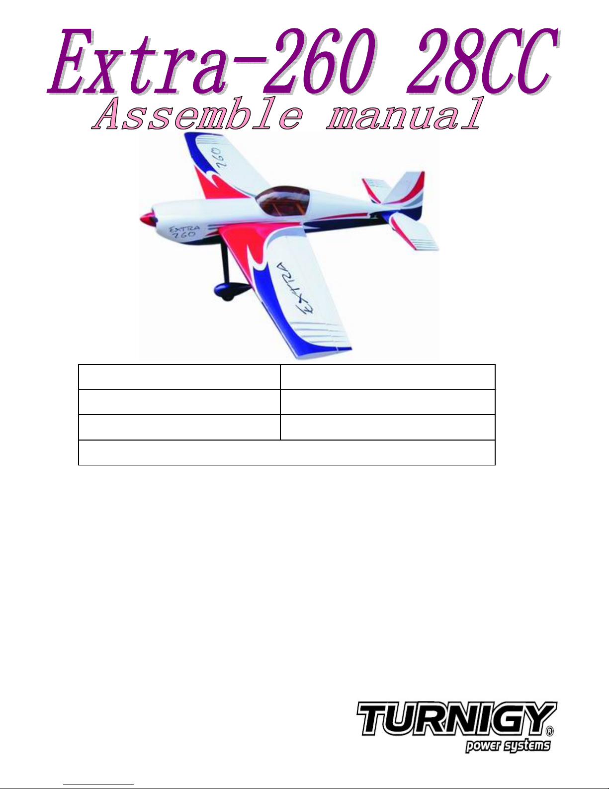
Gather the wings,
aluminium joiner and
other parts together.
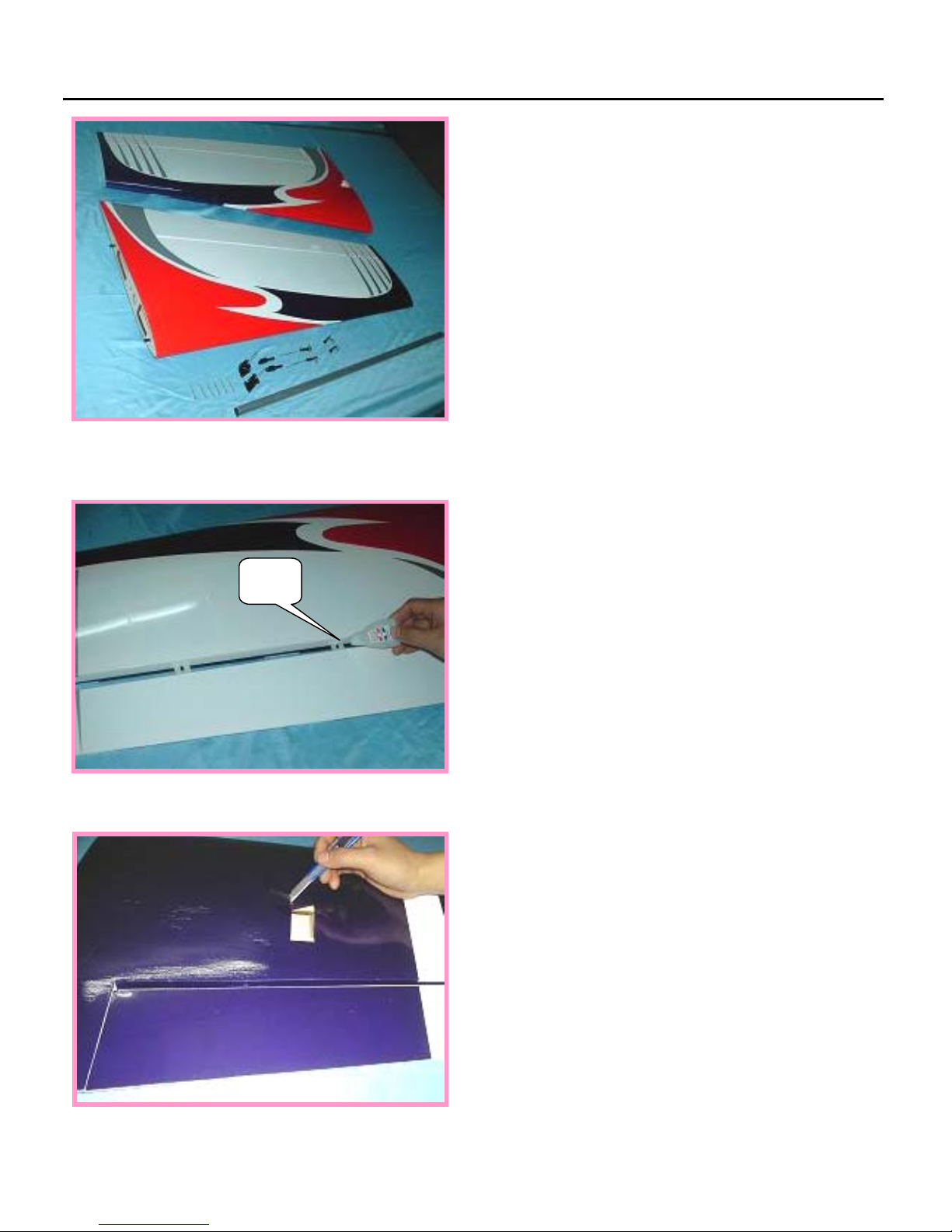
Insert the hinge into the
wing slot and secure it
with glue.
Cut away covering film
for the servo.
MAIN WING
AB
Glue
P2
Page 3
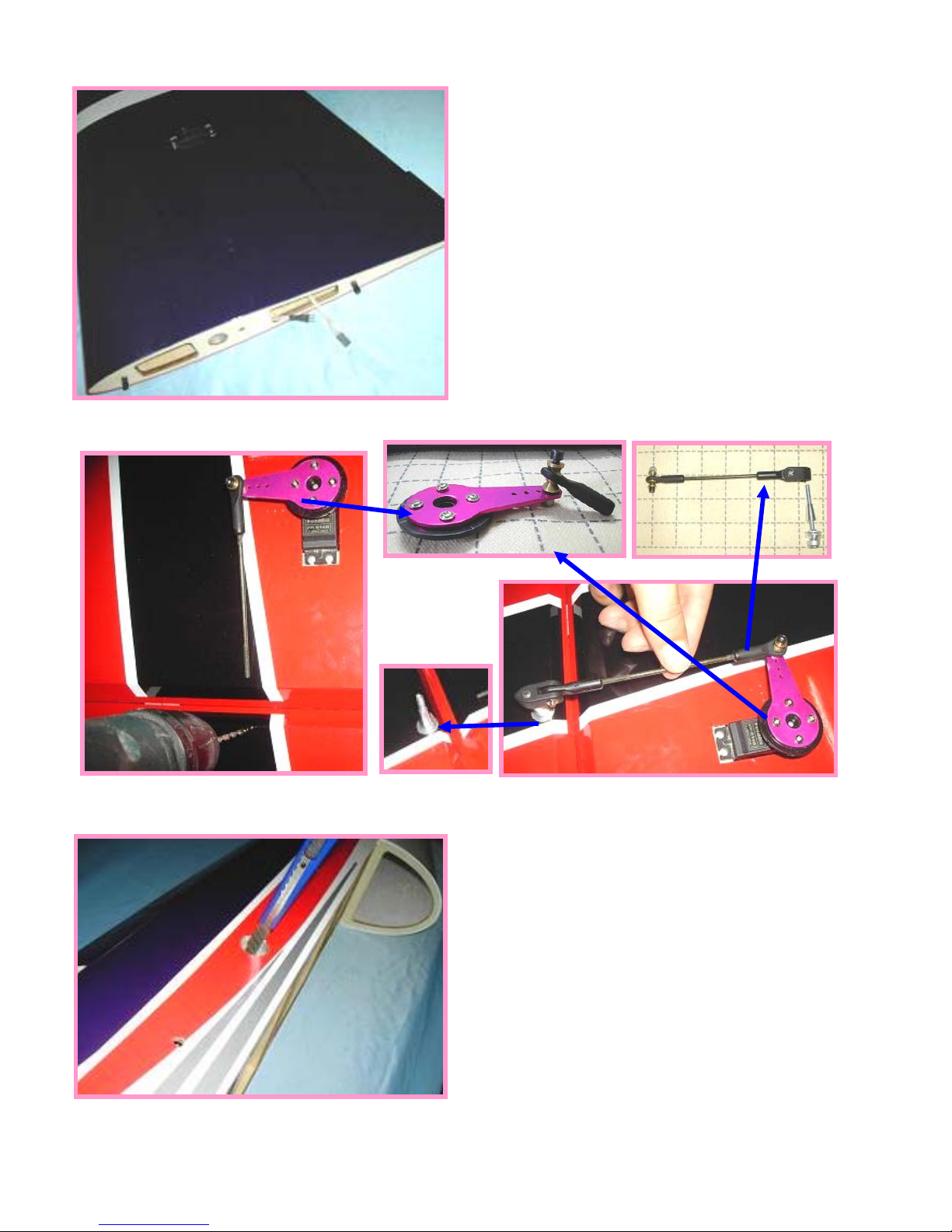
Put the servo into the
hole and pull out the
servo extension from main
wing.
Find out the holes in
each sides of fuselage,
then cut the film.
P3
Page 4
Connect the main wings and
the fuselage with joiner.
Also pull the extension
into the fuselage.
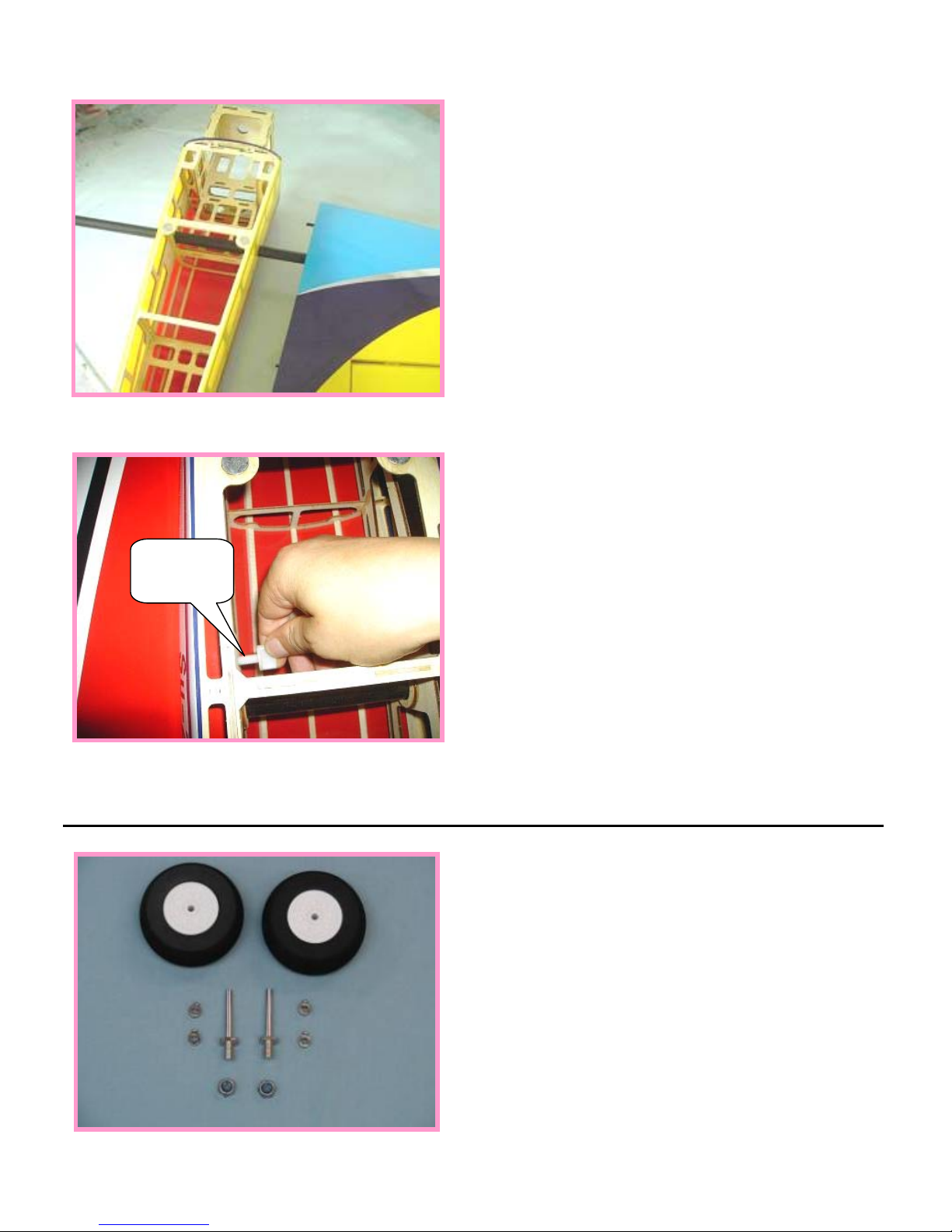
Fixup the wings with plastic
bolts on both sides.
Gather the wheels,axles and
collars as shown.
MAIN LANDING GEAR
Plastic
bolt
P4
Page 5
Permanently tighten the axle
to the gear strut by wrenches.
Install wheel pants with two
mounting bolts.
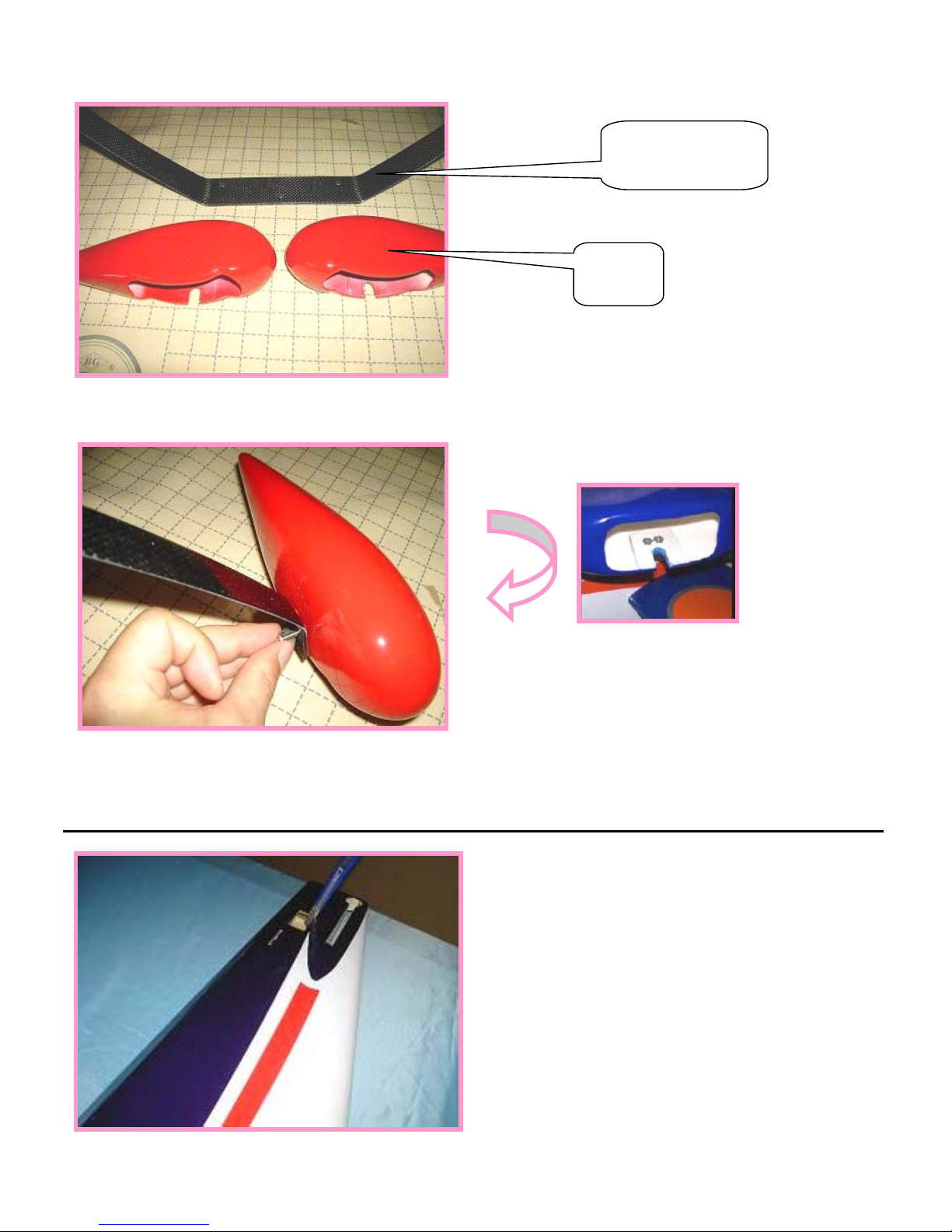
Find and cut the hole for
stabilizer and also the
servo holes.
TAIL WHEEL INSTALLATION
Carbon Fiber
Landing gear
Wheel
Pants
P5
Page 6

Cut away the film along
the edges, and glow the
stabilizer to the fuselage.
Cut the rudder film along
the edges, and glue the
rudder to the fuselage.
Securely glue up and
soaked up the hinge with
instant glue.
P6
Page 7

Bend the tail landing
gear to fit for the rudder
and insert it into the
rudder.
Glue the rudder to the
fuselage.
Glow the tail landing gear
to the rudder securely.
P7
Page 8

Install the tail wheel,
and fasten the presser
of the tail wheel to the
stabilizer by screws.
Insert elevator to the
tailplane with U shape wire.
Connect the control horn
to the linkage of the
servo.
ELEVATOR AND RUDDER
A
B
P8
Page 9

Tighten the second loop
through the brass swage
tube.
Crimp the brass tube with
a crimping tool or pliers.
Rudder
servo arm
Push
rods
P9
Page 10

Install rudder pushrod.
Install the ball linkege
connector.Calculate the
length proportion between
the servo arm and the
horn.Rotate the ball
linkage connector to an
appropriate position.
Place the hatch.
Use two screws to secure
it firmly.
Another method for the rudder
servo installation
P10
Page 11

Gather the MLD engine and
spare parts as shown.
The finished picture as shown.
Pay attention to:you have DLE and MLD for choice.
Install the DLE 30CC as shown.
ENGINE
P11
Page 12

P12
Page 13

Place the hatch.
Use two screws to secure
it firmly.
Mounting the cowling by
wood screws.
COWLING
FUEL TANK
P13
Page 14

-
mm
60-80mm
65-90mm
65-90mm
40-61mm
40-61mm
P14
Page 15

THE FINISHED PHOTO
Flight Model MFG CO
P15
 Loading...