

Digital
User’s Manual
March 13, 2020
P/N 998-2131
Revision 1.0
TURNER DESIGNS
1995 N. 1st Street
San Jose, CA 95112
Phone: (408) 749-0994
FAX: (408) 749-0998

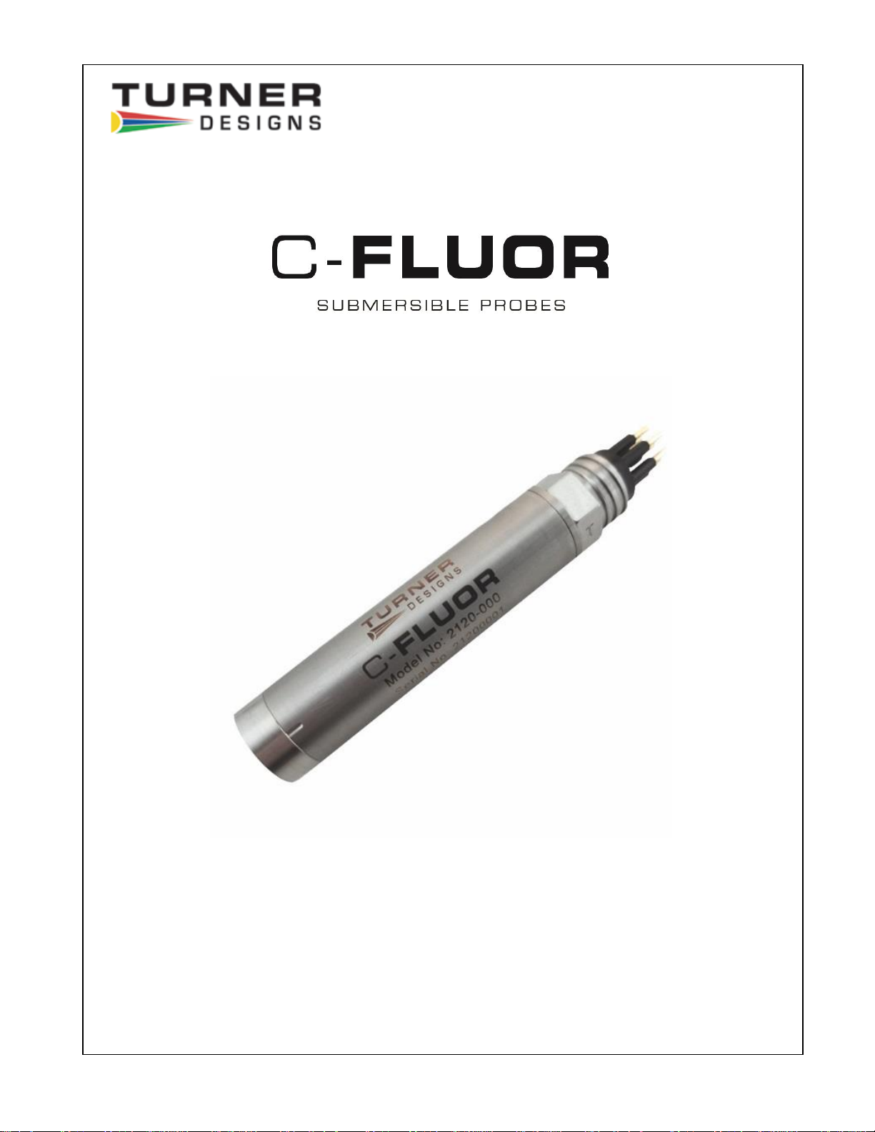
Digital C-FLUOR Submersible Probe
998-2131 Rev. 1.0 Page 2
Table of Contents
1.
Introduction
1.1
Description
4
2.
Inspection and Setup
2.1
Instrument Checklist
5
2.2
Configurations
5 2.3
Optional Accessories
5
2.4
Functional Test for Digital C-FLUOR with connector
7
2.5
Digital C-FLUOR with no connector
8
3.
Digital C-FLUOR Software & Functions
3.1
Setup
9
3.1.1
Polling Mode
9
3.1.2
Data Streaming Mode
10
3.13
Setting New Baud Rate
10
3.2
Calibration
11
3.2.1
Calibrating the Digital C-FLUOR Probe
11
3.2.2
Restoring Factory Calibration
12
4.
Maintenance and Warranty
4.1
Maintenance
13
4.1.1
Rinsing
13
4.1.2
Care for the bulkhead connector
13
4.1.3
Care for the Optics
13
4.2
Warranty Terms
13
4.3
Warranty Service
14
4.4
Out of Warranty Service
14
Appendices
A Specifications
16
B Recommended Lab Measurement Practices
17 C
Wiring Guide
18
D Pigtail Cable and Connector Information
19
E Digital C-FLUOR Probe Command List
20
Digital C-FLUOR Submersible Probe
998-2131 Rev. 1.0 Page 3
WASTE ELECTRICAL AND ELECTRONIC EQUIPMENT (WEEE)
DIRECTIVE
Turner Designs is in the business of designing and selling products that benefit the
well-being of our environment. Accordingly, we are concerned with preserving the
surroundings wherever our instruments are used and happy to work with customers
by complying with the WEEE Directive to reduce the environmental impact resulting
from the use of our products.
WEEE Return Process:
To arrange the return of an end-of-life product, proceed as follows:
If you purchased your instrument through a Turner Designs Distributor please
contact your local representative. They will instruct you where to return the endof-life product.
If you purchased your instrument directly from Turner Designs please contact
Turner Designs Customer Service
By Phone: 1-408-212-4041 or Toll Free: (877) 316.8049
By Email: Customer Service at support@turnerdesigns.com
Turner Designs will provide a WEEE RMA Number, a Shipping Account
Number, and a Ship to Address. Package and ship the product back to Turner
Designs.
The product will be dealt with per Turner Designs’ end-of-life recycling program in
an environmentally friendly way.

Digital C-FLUOR Submersible Probe
998-2131 Rev. 1.0 Page 4
1. Introduction
1.1 Description
The Turner Designs Digital C-FLUOR Submersible Probe is an accurate single-
channel detector that can be used for many different applications. Digital CFLUOR can be integrated into multi-parameter systems from which it receives
power allowing it to output digital ASCII data as concentration estimates for a
fluorophore of interest.
Digital C-FLUOR Probes are factory calibrated and a probe-specific calibration
certificate is included with each probe. The certificate contains information that
states the probe’s minimum level of detection and range of concentrations that
can be measured for the specific application.
Digital C-FLUOR Probes are manufactured with a Titanium housing and
connector, ideal for long-term deployments and able to withstand most corrosive
environments. It is available without a connector for integration flexibility; see
Section 2.2 for part numbers.
NOTE: Digital C-FLUOR Probes cannot be used with the C6 Multi-Sensor
Platform, Cyclops Explorer or Databank Handheld Datalogger.
Digital C-FLUOR Submersible Probe
998-2131 Rev. 1.0 Page 5
2. Inspection and Setup
2.1 Instrument Checklist
The Digital C-FLUOR Submersible Probe shipment package consists of:
A Digital C-FLUOR Submersible Probe that is configured and factory
calibrated for the specified fluorophore or material as noted by the
Identification Letter stamped on the connector:
“C” = Chlorophyll
“R” = Rhodamine
“F” = Fluorescein
“P” = Phycocyanin
“E” = Phycoerythrin
“U” = CDOM / FDOM
“O” = Crude Oil
“B” = Optical Brighteners
“T” = Turbidity
“D” = Red Excitation Chlorophyll
Calibration Certificate
Quick Start Guide
2.2 Configurations
C-FLUOR (Digital) P/N 2120-000-“Identification Letter”-232
C-FLUOR Without Connector (Digital) P/N 2120-000-“Identification Letter”-
NC-232
Note: No end cap is supplied for the C-FLUOR Without Connector (Digital) - see
Section 2.5. For end cap specifications, contact Support@turnerdesigns.com
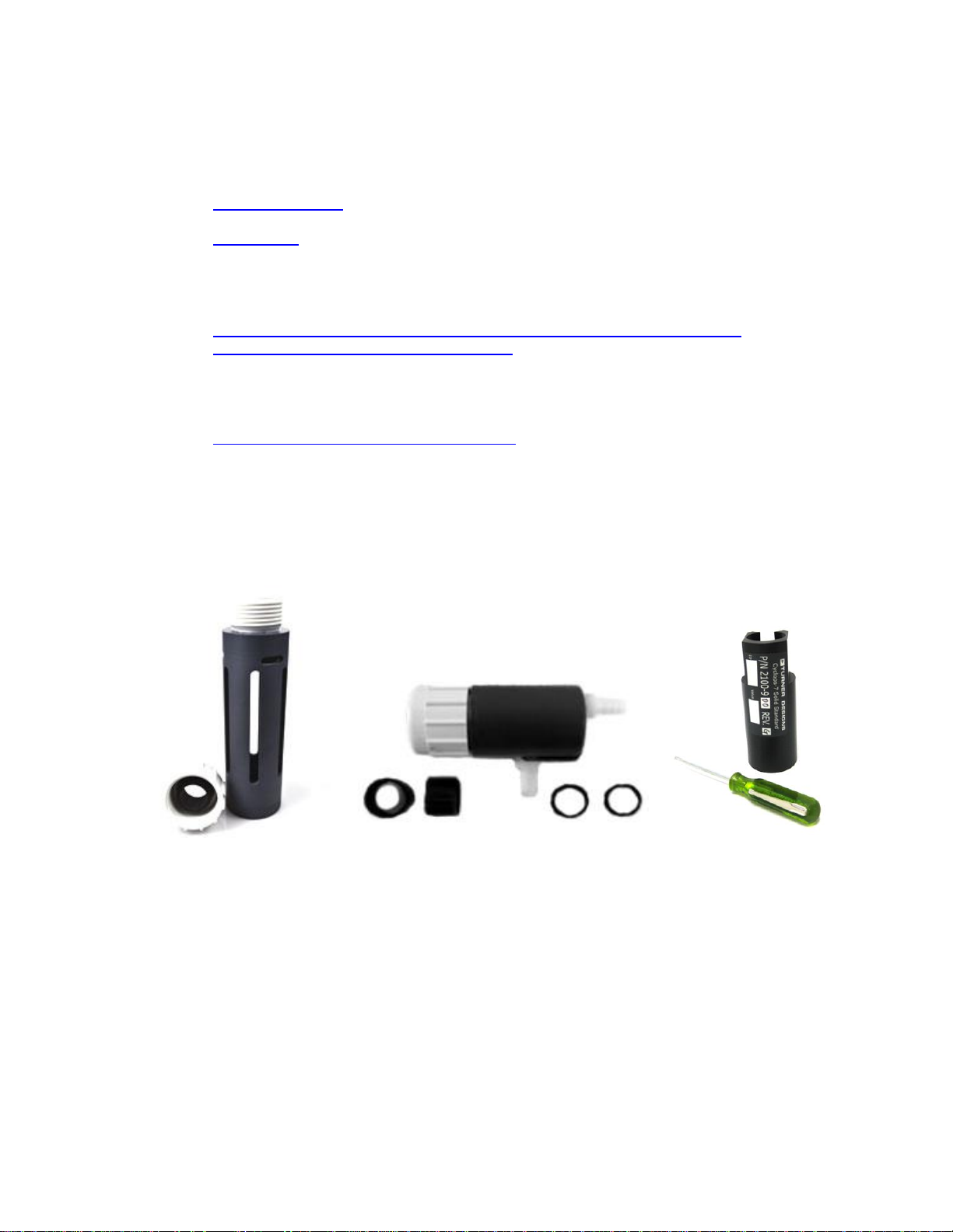
2.3 Optional Accessories
RS-232 Programming Kit P/N 2120-900 includes RS-232 Programming
cable P/N 2120-160 and 12-volt power supply P/N 7000-941
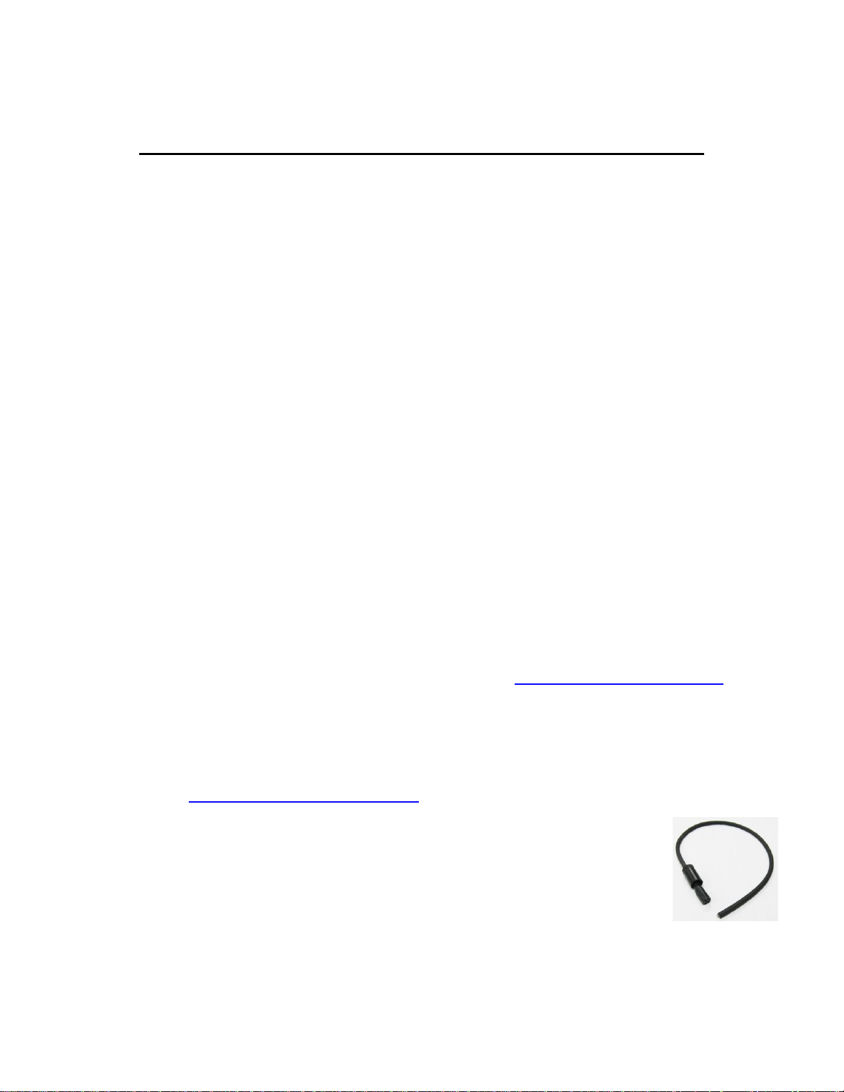
Pigtail Cables with Locking Sleeve - see Appendix D for more information
0.6 Meter Pigtail Cable with Locking Sleeve P/N 2100-750
5 Meter Pigtail Cable with Locking Sleeve P/N 2100-755
10 Meter Pigtail Cable with Locking Sleeve P/N 2100-751
Pigtail Cables longer than 10 meters will require RS422 converter
25 Meter Pigtail Cable with Locking Sleeve P/N 2100-752
Note: Pigtail Cables should NOT be used to tow instruments.
Digital C-FLUOR Submersible Probe
998-2131 Rev. 1.0 Page 6
Flowthrough Cap P/N 2100-600
Shade Cap P/N 2100-701
Note: We recommend use of the shade cap as it provides a fixed distance
for sample measurement and minimizes effects from ambient light.
Solid Secondary Standard (SSS) for in vivo Chlorophyll, Phycocyanin,
Phycoerythrin, Rhodamine, Fluorescein P/N 2100-900
Note: The SSS can be used for both C-FLUOR and Cyclops for the
applications specified above.
Solid Secondary Standard (SSS) for UV - CDOM / FDOM, Optical
Brighteners, and Crude Oil P/N 2100-904
Note: The UV SSS can be used for both C-FLUOR and Cyclops for the
applications specified above, as well as Cyclops Refined Fuels and
Tryptophan sensors.
Flow Cap
Shade Cap
Solid Secondary Standard

Digital C-FLUOR Submersible Probe
998-2131 Rev. 1.0 Page 7
2.4 Functional Test for Digital C-FLUOR with connector
To perform a functional check on a Digital C-FLUOR Probe, connect the probe
to your computer following the instructions below, using the RS-232
Programming Cable as shown in Figure 1:
Additional Equipment required for functional tests:
RS-232 Programming Cable P/N 2120-160
12-volt power supply P/N 7000-941
Computer with USB port
Note: Supply voltages greater than 15 VDC will damage the probe.
1) Insert the Programming Cable’s USB plug into an available USB port on your
computer and wait for the drivers to automatically install.
2) Once USB drivers have installed, download and install Digital C-FLUOR’s
Software from www.turnerdesigns.com.
3) After software has successfully installed, double-click the software’s icon
which should have been automatically added to your desktop.
4) When software has opened, supply power to the instrument using the 12-volt
power supply specified ensuring the power supply is plugged into an AC
source.
5) Click “Communicate With C-FLUOR” and wait a few minutes for the software
to detect the connected probe.
6) When connected, C-FLUOR Communication Status radio button will change
from red to green.
Figure 1

Digital C-FLUOR Submersible Probe
998-2131 Rev. 1.0 Page 8
With the C-FLUOR connected to your computer and power supply, and
communicating with the software, answer questions 1-3 by making the following
functional tests:
1. Is the LED on?
Hold a piece of white paper about ½ an inch in front of the optical head to
ensure the LED is ON.
Note: This test does not work for Turbidity probes because they use
infrared which is not visible.
2. Is there output?
Click the “Get Datapoint” button; if a value is displayed in the box then the
instrument’s output is working.
3. Does the output change?
Move the light source closer to the piece of paper and again click the “Get
Datapoint” button; if the output increases then the instrument’s detector is
working.
2.5 Digital C-FLUOR with no connector
Digital C-FLUOR can be purchased without a 6-pin bulkhead connector or end
cap. If the No Connector version is purchased the Digital C-FLUOR Probe will
have bare wires as shown in the figure below. See Section 2.1 for identification
letters.
C-FLUOR Without Connector (Digital) P/N: 2120-000-“Identification Letter”-NC-232
Use the wiring guide in Appendix C to wire the Digital C-FLUOR Probe for serial
communication with your computer or controller. Use the command list in
Appendix E to configure your Digital C-FLUOR probe for your data logger or
third-party instrument that accepts an ASCII data string output.
Note: The Digital C-FLUOR Probe is factory calibrated; to re-calibrate the
probe you must connect to a computer via serial connection and use
Digital C-FLUOR Probe software. See Section 3.2 for Calibration.

Digital C-FLUOR Submersible Probe
998-2131 Rev. 1.0 Page 9
3. Digital C-FLUOR Software & Functions
Software is used to configure Digital C-FLUOR Probes for digital integration and/or
deployment. Digital C-FLUOR Probes do not store data internally, ASCII data
strings are sent out via serial communication.
3.1 Setup
The Setup tab displays the probe’s serial number and the probe-specific
application; these values cannot be edited. There are two modes that can be
selected, Polling and Data Streaming.
3.1.1 Polling Mode
Polling Mode is used when data storage or power is limited. Power is
supplied to the probe and a command is used to trigger the probe to
make a measurement. See Appendix E for command list. Every poll
command will return an individual ASCII data string that contains a
concentration value relative to the fluorescence detected. To activate
polling mode, simply put a checkmark into the box next to the “Polling”
function and select QUIT to exit the software. Once power is supplied to
the probe, it will be ready to receive a poll command after 0.5 seconds.

Digital C-FLUOR Submersible Probe
998-2131 Rev. 1.0 Page 10
3.1.2 Data Streaming Mode
Data streaming mode provides a continuous ASCII digital output string at
selectable data rates. Rates can be accessed using the pull-down menu
located next to the “Data Streaming” box. To activate Data Streaming
mode you must first choose a Rate and then put a checkmark in the box
next to the “Data Streaming” function. The Data Streaming radio button
will change from red to green indicating the unit is streaming data.
Note: Data rates faster than 1 reading per second will be updated at
a rate of 1 reading per second in the Datapoint Value box. To see
the actual data rate users should run a terminal emulator such as
Hyperterminal to view actual data rate set.
3.1.3 Setting a New Baud Rate
Users can change the Baud Rate by clicking the “Set New Baud Rate”
box which will open a window giving the option to select any of five
available baud rates. Place a checkmark in the box next to the desired
baud rate and click “Set New Rate”. The “Current Baud Rate” box will
display the selected Baud Rate.

Digital C-FLUOR Submersible Probe
998-2131 Rev. 1.0 Page 11
3.2 Calibration
The Digital C-FLUOR Probe is factory calibrated and the calibration values are
stored in memory. The probe can be re-calibrated by users via software if sitespecific calibrations are desired for increased accuracy. New calibration values
will be stored in memory without overwriting or erasing factory calibration values.
This allows users to restore factory calibration values if desired.
Note: Restoring factory calibration values will erase all customer
calibration values.
To calibrate Digital C-FLUOR you’ll need the following:
- PC with Digital C-FLUOR Software
- RS-232 Programming Cable P/N 2120-160
- 12-Volt Power Supply P/N 7000-941
- Blank solution
- Standard solution of known concentration
- Blackened or dark 500 ml beaker/container
3.2.1 Calibrating the Digital C-FLUOR Probe
1) See section 2.4 Functional Test for Digital C-FLUOR with connector
on how to connect to your computer.
2) Click the “Calibration” tab.
3) Enter the known concentration of your Standard Solution in the
Concentration Value box. Note: Only values greater than 1 are
valid.
4) Fill your 500 ml beaker with blank solution.
5) Submerge the probe’s optical head no more than an inch below the
surface of the blank solution. See Appendix B for recommended lab
practices.
SET FIRST

Digital C-FLUOR Submersible Probe
998-2131 Rev. 1.0 Page 12
6) Click the “Calibrate C-FLUOR” button, then click “OK”.
7) Wait for the progress bar to complete.
8) When prompted to insert C-FLUOR into Calibration Solution, remove
the probe from the blank solution.
9) Empty the blank solution from the beaker and wipe the beaker dry.
10) Fill your 500 ml beaker with standard solution.
11) Submerge the probes optical head no more than an inch below the
surface of the standard solution. See Appendix B for recommended
lab practices.
12) Click “OK”.
13) Wait for the progress bar to complete.
14) Click “Yes” to save the new calibration.
15) Click “Get Datapoint” to read the standard solution with the newly
calibrated probe; you should see the Concentration Value you
entered displayed in the “Datapoint Value” box confirming the
calibration was saved.
3.2.2 Restoring Factory Calibration
To restore the factory calibration of your Digital C-FLUOR Probe, you’ll
need to connect your probe to a computer with Digital C-FLUOR
software, communicate with your probe using the software and click on
the Calibration tab. Then click “Restore Factory Calibration”. You will be
asked if you wish to continue, select “Yes” to restore or “No” to keep your
custom calibration.
If factory calibration is restored, the software will display Factory
Calibration was restored meaning your custom calibration was deleted
and cannot be retrieved.
Note: Once customer calibrations are deleted, they cannot be
retrieved. Please be sure you intend to delete your custom
calibration before choosing to restore to factory calibration.
Will be
displayed
after
restoring
factory
calibration

Digital C-FLUOR Submersible Probe
998-2131 Rev. 1.0 Page 13
4. Maintenance and Warranty
4.1 Maintenance
4.1.1 Rinsing
The C-FLUOR should be rinsed or soaked in fresh water following each
deployment until it is completely clean again.
4.1.2 Care for the bulkhead connector
A light coat of Silicone spray should be used on the rubber of the male
pins of the bulkhead to aid in sealing. The manufacturer recommends
3M™ Silicone Lubricant Spray or Loctite 8021 spray.
Note: You should avoid using silicone grease. Do NOT use WD-40,
it will destroy the connectors.
4.1.3 Care for the optics
The optical window should be visually inspected after each deployment
following a soaking in fresh water. If cleaning is needed, use optical
tissue to clean the window with soapy water.
Note: The C-FLUOR should NOT come in contact with any organic
solvents (i.e. acetone, methanol) or strong acids and bases.
4.2 Warranty Terms
Turner Designs warrants the C-FLUOR and accessories to be free from defects
in materials and workmanship under normal use and service for a period of 12
months from the date of shipment from Turner Designs with the following
restrictions:
Turner Designs is not responsible for replacing parts damaged by accident
or neglect. Your instrument must be installed according to instructions in the
User’s Manual. Damage from corrosion is not covered. Damage caused by
customer modification of the instrument is not covered.
This warranty covers only Turner Designs products and is not extended to
equipment used with our products. We are not responsible for incidental or
consequential damages, except in those states where this limitation is not
allowed. This warranty gives you specific legal rights and you may have
other rights which vary from state to state.
Damage incurred in shipping is not covered.

Digital C-FLUOR Submersible Probe
998-2131 Rev. 1.0 Page 14
4.3 Warranty Service
To obtain service during the warranty period, the owner shall take the following
steps:
1. Write, email or call Turner Designs Technical Support and describe as
precisely as possible the nature of the problem.
Phone: 1 (877) 316-8049
Email: support@turnerdesigns.com
2. Carry out any adjustments or tests as suggested by Technical Support.
3. If proper performance is not obtained you will be issued a Return Materials
Authorization number (RMA) to reference. Package the unit, write the RMA
number on the outside of the shipping carton, and ship the instrument,
prepaid, to Turner Designs. If the failure is covered under the warranty
terms the instrument will be repaired and returned free of charge, for all
customers in the contiguous continental United States.
For customers outside of the contiguous continental United States who
purchased equipment from one of our authorized distributors, contact the
distributor. If you purchased directly, contact us. We will repair the
instrument at no charge. Customer pays for shipping, duties, and
documentation to Turner Designs. Turner Designs pays for return shipment.
Custom duties, taxes and fees are the responsibility of the customer.
4.4 Out-of-Warranty Service
Follow steps for Warranty Service as listed above. If Technical Support can
assist you by phone or correspondence, we will be glad to, at no charge. Repair
service will be billed on a fixed price basis, plus any applicable duties and/or
taxes. Shipment to Turner Designs should be prepaid. Your bill will include
return shipment freight charges.
Address for Shipment:
Turner Designs, Inc.
1995 N. 1st Street
San Jose, CA 95112

Digital C-FLUOR Submersible Probe
998-2131 Rev. 1.0 Page 15

Digital C-FLUOR Submersible Probe
998-2131 Rev. 1.0 Page 16
Appendix A: Specifications
Parameter
Specification
Full Range Linearity
0.99 R2
Power Draw @ 12V
CHL, RWT, PC, PE, F, CDOM/fDOM, Oil, & OB = 22mA
Turbidity = 20mA
Input Voltage
3 – 15 VDC
Signal Output
ASCII Digital Data String (RS-232)
Temperature Range
Ambient: 0 to 50 C
Water Temp: -2 to +50 C
Light Source
Light Emitting Diode
Excitation Wavelength
Visible – CHL, RWT, PC, PE, F
UV – CDOM/fDOM, Oil, OB
IR – Turbidity
Detector
Photodiode
Detection Wavelengths
400 – 850 nm
T99
< 0.6 seconds
Housing Material
Titanium
Dimensions
C-FLUOR
L: 5.2 in., 13.24 cm
D: 0.875 in., 2.23 cm
No Connector C-FLUOR
L: 3.8 in., 9.68 cm
D: 0.875 in., 2.23 cm
Depth Rating
2,000 meters
Weight
3.3 oz; 95 gm

Digital C-FLUOR Submersible Probe
998-2131 Rev. 1.0 Page 17
Appendix B: Recommended Lab Measurement Practices
Recommended Lab Practices for Measurements
The following steps will improve the accuracy and repeatability of your measurements,
especially at low concentration levels:
1. Use a non-fluorescent container for your water samples. Note: Plastic may
fluoresce and interfere with the sample’s fluorescence.
2. If using a glass container, place the container on a non-reflective black surface.
3. Ensure that the probe is more than 3 inches above the bottom of the container.
4. Ensure that the probe is in the center of the container and has more than 2 inches
clearance between the cirumference of the probe and the inside surface of the
beaker.
>3 inches
Dark/Black
Non-Reflective
Surface
>2 inches all
round
Calibrated
Sensor
No Air Bubbles
On Optical
Surface
Glass Beaker

Digital C-FLUOR Submersible Probe
998-2131 Rev. 1.0 Page 18
Appendix C: Wiring Guide
C-FLUOR
Pins/Wires
Pin
Number
Function
Connection
Red
1
Supply Voltage
3 – 15 VDC
PSU – Positive Connection
Black 2 Supply Ground, 0VDC
PSU – Ground Connection
Orange 3 Receive Data
RX
Green 4 Transmit Data
TX
Blue 5 Digital Ground
GND
Yellow
6
N/A
-
Note: Pin 6 is not used.
Pigtail Connector
and Wire Color
3
6
4
2
1
5
5
2
4
4 6 1
3
C-FLUOR Pins
and Wire Color
3 4 2 1 5 6 6
3
6
4
2
1
5
5
2
4
4 6 1
3
3 3
6 6
4 4
2 2
1
5 5
5
2
4
4 6 1 3 3 4 2 1 5 6 6
3 4 2 1 5 6 3
3
4 4
2 2 1 5 5

Digital C-FLUOR Submersible Probe
998-2131 Rev. 1.0 Page 19
Appendix D: Pigtail Cable and Connector Information
Dimension details of 24” length cable with 20 gauge colored lead wire, connects to 6 pin
male connector. (Cable manufacturer/Part No: IMPULSE/MCIL-6-FS)
Female locking sleeve,
(Impulse P/No. MCDLS-F)
C-FLUOR Pins
and Wire Color
3
4
2
1
5 6 3
4
2
1
5 3 4
2
1
5
3 3
4 4
2 2
1
5 5
Pigtail Connector
and Wire Color
3
6
4
2 1 5
5
2
4
4
6 1 3
3
6
4
2 1 5
5
2
4
4
6 1 3
3 3
6 6
4 4
2 2 1 5 5
5
2
4
4
6 1 3
Note: A maximum cable length of 30 feet can be used for digital
data transfer from Digital C-FLUOR Probes to computers or data
loggers. For long distance data transfer or communication, the
digital RS232 signal should be converted to RS422.

Digital C-FLUOR Submersible Probe
998-2131 Rev. 1.0 Page 20
Appendix E: Digital C-FLUOR Probe Command List
Digital C-FLUOR Probes can be programmed using commands via serial
communication with terminal emulators such as Hyperterminal, TerraTerm, PuTTY,
Procomm Plus, AlphaCom, etc or third-party communication systems. This is helpful
for integrators as they don’t need software for programming integrated probes. Use
the following settings for serial connection:
Baud Rate: Use the rate that was displayed in the Digital C-FLUOR Software.
Data bits: 8
Parity: None
Stop bits: 1
Flow Control: None
Once connected, you can communicate using the list of commands below to setup,
collect information, and program Digital C-FLUOR Probes:
Command
Name
Note
I!
Sensor Information
For Probe Information
C!
Calibration Information
For Calibration Values
Bxxxx!
Set Baud Rate
“xxxx” refers to baud rate
(9600, 14400, 19200, 38400, 57600)
Sxx!
Streaming Output Rate
Puts probe into streaming mode Use
table below to determine “xx”
P!
Polling Mode
Puts probe into polling mode
R!
Read Command
Only when in Polling mode
M!
Report the Current Mode
Returns S with rate or P
xx
Readings per second
Seconds between
01
Not Available
02
16 03 8
04 4
05 2
06
1
1 (factory default)
07 2
08 5
09 10
10 15
11 30
12 60
13 120
14 300
15 600
16 1800
17 3600
 Loading...