

Page 1
Turner OCTO® Assembly Guide
SECTION 1.
Assembly Guide
©Turner Access Ltd
65 Craigton Road, Glasgow, G51 3EQ, Scotland
T: +44 (0) 141 309 5555 F: +44 (0) 141 309 5436 www.turner-octo.com
Section 1 Page 1 TA3/01/50/01_Iss1Rev3
Rev.No.Jan17/Rev3
Page 2

Turner OCTO® Assembly Guide
SECTION 1. Contents
CONTENTS
1.1 Introduction............................................................................................................4
1.2 Pre-use Inspection & Selection............................................................................5
1.3 Components...........................................................................................................6
1.3.1 Basic Components....................................................................................6
1.3.2 Component Fixing Hints............................................................................7
1.3.3 Access Methods........................................................................................9
1.4 Safety Information................................................................................................11
1.4.1 General Safety Notes...............................................................................11
®
1.4.2 GuardAid
................................................................................................12
(i) User Instructions.................................................................................12
®
(ii) Wall Scaffold Assembly Procedure using GuardAid
.........................15
1.4.3 Fall Arrest.................................................................................................23
®
1.5 Assembly Procedures for Turner OCTO
System Scaffolds...........................24
1.5.1 Tied Wall Scaffold....................................................................................25
(i) Fully Boarded......................................................................................25
(ii) Top Lift...............................................................................................29
(iii) Corner Returns..................................................................................30
1.5.2 Independent Towers................................................................................34
(i) Fully Boarded......................................................................................34
(ii) Top Lift...............................................................................................35
(iii) Mobile................................................................................................36
(iv) Inspection & Maintenance Guidance Notes for Mobile Structures....37
1.5.3 Birdcages.................................................................................................39
(i) Linked Birdcage...................................................................................40
1.5.4 Freestanding Structures..........................................................................42
©Turner Access Ltd 65 Craigton Road, Glasgow, G51 3EQ, Scotland
Section 1 Page 2 TA3/01/50/01_Iss1Rev3
Rev.No.Jan17/Rev3
Page 3

Turner OCTO® Assembly Guide
SECTION 1. Contents
1.5.5 Cantilever Brackets.................................................................................45
(i) Inside Boards.......................................................................................45
(ii) Cantilever Bracket with End Plate......................................................47
(iii) Cantilever Bracket with Cup..............................................................47
1.5.6 Circular Structures...................................................................................49
1.5.7 Suspended Scaffolds...............................................................................51
1.5.8 Pre Scaffold Handover Inspection...........................................................53
1.5.9 Maintenance............................................................................................53
1.5.10 Dismantling Procedure............................................................................54
1.6 Anchoring.............................................................................................................55
1.6.1 Tie Patterns for unclad scaffolds.............................................................55
1.6.2 Tie Loads.................................................................................................56
1.7 Maximum Heights................................................................................................57
1.7.1 Assembly Criteria - Unclad Tied Wall Scaffold Examples.......................58
1.7.2 Maximum Heights Unclad Tied Scaffolds (Foot Tied with Horizontal)....59
1.7.3 Maximum Heights Unclad Tied Scaffolds (Foot Tied with Guardrail)......60
1.7.4 Maximum Heights Unclad Tied Scaffolds (Non Foot Tied)......................61
1.8 Transport and Storage.........................................................................................62
1.9 References............................................................................................................63
T: +44 (0) 141 309 5555 F: +44 (0) 141 309 5436 www.turner-octo.com
Section 1 Page 3 TA3/01/50/01_Iss1Rev3
Rev.No.Jan17/Rev3
Page 4

1.1 INTRODUCTION
Turner OCTO® Assembly Guide
SECTION 1.1 Introduction
This Assembly Guide contains the necessary information required to correctly assemble
Turner OCTO
®
System Scaffolds in accordance with appropriate methods of safe assembly.
The provision and utilisation of collective protection equipment and methodology is
recommended where practicable for installers of Turner OCTO® System Scaffolding.
Installers / Dismantlers of Turner OCTO® System Scaffolding must also be competent,
relative to the type of scaffold to be erected, dismantled or altered.
This Assembly Guide provides instruction for foot tied, non-foot tied, and pedestrian
categories (as listed within the Assembly Guide) built from the ground or other suitable
foundation.
Types of Turner OCTO® System standard conguration included within this Assembly Guide
are detailed on the Contents Page and limited to the maximum heights as indicated in
Section 1.7 Maximum Heights (page 57).
This Assembly Guide should be used in conjunction with a suitable Risk Assessment and
Method Statement (by user) relative to the project to be undertaken. It must be noted that
all employers have a responsibility to ensure that work methods (practices) and adequate
facilities / resources (including work equipment) are provided to eliminate or minimise risks,
in accordance with current legislation.
A complete separate safe system of work (Method Statement) is required for all other types
of scaffold.
Sufcient training, combined with necessary experience, must also be considered and be
appropriate to achieve competency to build or dismantle a particular scaffold type in question.
Please ensure you read and fully understand the manual, and follow the content during
scaffold erection and ensure that the scaffold is complete prior to use and / or handover.
This Manual must be made available to the user / installer of the Turner OCTO® Scaffold
System at all times.
Only competent and qualied personnel should undertake assembly, dismantling and
alteration (and organisation, planning and supervision) of basic Turner OCTO® standard
congurations, and consideration should be given to providing additional (minimum) training
beforehand, if required.
©Turner Access Ltd 65 Craigton Road, Glasgow, G51 3EQ, Scotland
Section 1 Page 4 TA3/01/50/01_Iss1Rev3
Rev.No.Jan17/Rev3
Page 5

Turner OCTO® Assembly Guide
SECTION 1.2 Pre-use Inspection & Selection
1.2 PRE-USE INSPECTION & SELECTION
To ensure that a scaffold is assembled in a manner that prevents its component parts from
being accidentally displaced at any time, it is important that the following checks are carried
out:
• Ensure that all necessary components and safety equipment are available and
operational.
• Each component should be visually inspected prior to use and should be free from
defects.
• Steel components should be straight with no sign of corrosion, cracks or splits that
would impair strength or safety.
• Deck locks should be in good working order; hooks should be free of cracks and
corrosion, and bolts should be tight and locking nuts tted.
• Stiles or Ply inserts should not be punctured or worn to a degree that would impair
strength or safety.
Damaged or incorrect components must not be used.
Pre-use inspection should ONLY be carried out by a competent person.
T: +44 (0) 141 309 5555 F: +44 (0) 141 309 5436 www.turner-octo.com
Section 1 Page 5 TA3/01/50/01_Iss1Rev3
Rev.No.Jan17/Rev3
Page 6
1.3 COMPONENTS
Turner OCTO® Assembly Guide
SECTION 1.3 Components
Turner OCTO
®
System components for basic use are described in this section for assembly,
dismantling and alteration of Turner OCTO® System standard congurations. For detailed
component information, refer to the Turner OCTO® Component Identication Guide.
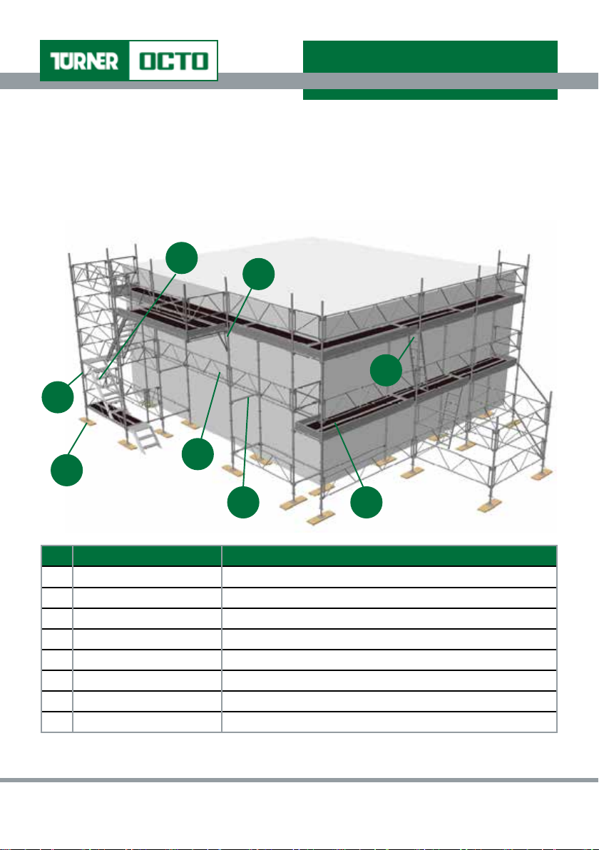
1.3.1 Basic Components
7
8
6
2
3
1
4 5
No. Component Details
1. Adjustable Base Jack Enables adjustment up to 500mm
2. Standard Sizes: 4m; 3m; 2m; 1m; 0.5m
3. Bracing Guardrail Sizes: 3.5m; 2.5m; 1.75m; 1.25m; 1m; 0.7m
4. Horizontal Sizes: 3.5m; 2.5m; 1.75m; 1.25m; 1m; 0.7m
5. Deck Sizes: 3.5m; 2.5m; 1.75m; 1.25m; 1m; 0.7m
6. Ladder Access Deck Sizes: 3.5m; 2.5m
7. Alloy Stair Stair access between working platform levels
8. Cantilever Bracket Sizes :1.25m; 1m; 0.7m; 0.45m; 0.30m; 0.1m
Note The sizes shown are basic sizes, other sizes available. Please ask for details.
©Turner Access Ltd 65 Craigton Road, Glasgow, G51 3EQ, Scotland
Section 1 Page 6 TA3/01/50/01_Iss1Rev3
Rev.No.Jan17/Rev3
Page 7

Turner OCTO® Assembly Guide
SECTION 1.3 Components
1.3.2 Component Fixing Hints
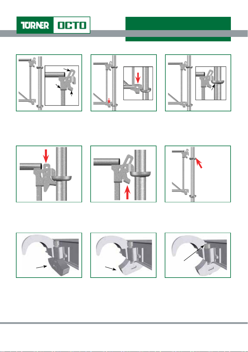
Horizontals
Saddle
Wedge
1. Turn the Horizontal upside
down at an angle of approx.
45° and shake.
4. Slide the Saddle over to the
Standard.
Wedge
....until the top of the Wedge
is level with the top of the
Horizontal.
Note If the Horizontal and Standard
are not level and plumb, the Wedge
may be difcult to drive.
2. The Wedge and Saddle will
then automatically fall back
into the preset position.
5. Lift Wedge and point
bottom of Wedge towards the
Standard.
7. To de-mount Horizontal,
drive Wedge vertically upwards
to loosen.
3. Position the Locking Head by
turning the Horizontal approx.
45° and rotate into the cup.
6. Drive Wedge down at an
angle of 45º initially towards
the Standard....
8. Lift the Wedge clear, slide
Saddle backwards and lift
Horizontal from cup.
T: +44 (0) 141 309 5555 F: +44 (0) 141 309 5436 www.turner-octo.com
Section 1 Page 7 TA3/01/50/01_Iss1Rev3
Rev.No.Jan17/Rev3
Page 8
Guardrails
Turner OCTO® Assembly Guide
SECTION 1.3 Components
Wedge
Ledge
Cup
Saddle
1. Preset Guardrail by lifting
Wedge and resting it on ledge
within the Guardrail.
Note Saddle will hang loosely leaving
space to t hook into cup.
4. Drive vertically until level
with the top of the Guardrail.
Decks
Unlocked
1. Push Deck from below and
through bay, then slide back
along bay until the hooks are in
line with the Horizontal. Place
Deck onto Horizontal.
2. Locate top and bottom
hooks of Guardrail in cups
(0.5m apart). Hint Tap lower hook
with hammer to ensure that it is
properly located in cup.
5. To de-mount Guardrail, drive
Wedge vertically upwards to
loosen.
Locked
2. Ensuring that Deck ts
correctly in bay to be decked
out and there is no movement
in the Deck, lock in position.
3. Lift Wedge clear of ledge
within the Guardrail to the
Vertical position and allow to
drop and loosely engage.
6. Lift the Wedge clear, rest on
ledge and lift Guardrail from cup.
OCTO® Lock
3. The OCTO® Deck has the
added benet of being locked
permanently by fully engaging
the OCTO® Lock using the
appropriate OCTO® tool.
©Turner Access Ltd 65 Craigton Road, Glasgow, G51 3EQ, Scotland
Section 1 Page 8 TA3/01/50/01_Iss1Rev3
Rev.No.Jan17/Rev3
Page 9
Turner OCTO® Assembly Guide
SECTION 1.3 Components
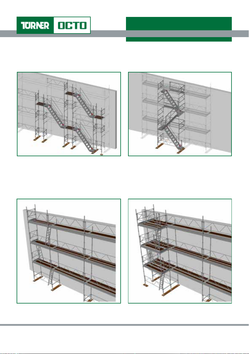
1.3.3 Access Methods
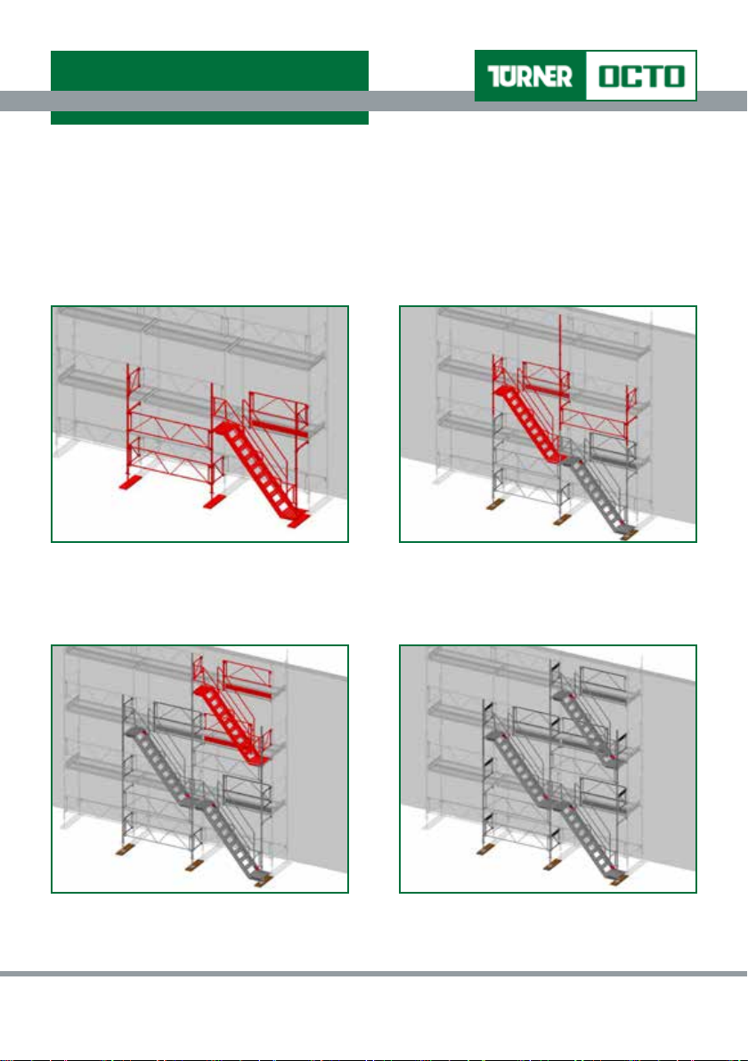
Stairway Access
Prior to the commencement of any scaffolding operations, please refer to Sections 1.4.1
General Safety Notes and 1.5 Assembly Procedures.
• 0.7m External Stairway Access (2.5m bay)
1. Assemble 0.7m wide bay to external face
of facade scaffold. Fit Guardrail Post and
2. Continue to assemble next lift and t
Stair unit to 2nd lift.
1.75m Bracing Guardrail to allow walk off
from Stair unit when tted.
3. Fit Guardrail Post and 1.75m Bracing
4. Complete.
Guardrail to allow next lift Stair unit to be
placed.
T: +44 (0) 141 309 5555 F: +44 (0) 141 309 5436 www.turner-octo.com
Section 1 Page 9 TA3/01/50/01_Iss1Rev3
Rev.No.Jan17/Rev3
Page 10
Turner OCTO® Assembly Guide
SECTION 1.3 Components
• 0.7m External Stairway Access
(3.5m bay)
• 1.25m External Stairway Access
(2.5m bay)
Ladder Access
• Internal Ladder Access with Hatches • External Ladder Access with Hatches
©Turner Access Ltd 65 Craigton Road, Glasgow, G51 3EQ, Scotland
Section 1 Page 10 TA3/01/50/01_Iss1Rev3
Rev.No.Jan17/Rev3
Page 11

Turner OCTO® Assembly Guide
SECTION 1.4 Safety Information
1.4 SAFETY INFORMATION
1.4.1 General Safety Notes
Only competent and qualied personnel should undertake assembly, dismantling and alteration
(and organisation, planning and supervision) of basic Turner OCTO
®
standard congurations,
and consideration should be given to providing additional (minimum) training beforehand, if
required.
Ensure that all necessary components and safety equipment are available and operational.
Inspect components for signs of damage or incorrect functioning prior to use. Damaged or
incorrect components should not be used.
Erect Exclusion Zone and t Warning Signs to comply with current legislation.
Before assembling the scaffold structure, check that the location for the structure does not
present any hazards during assembly, dismantling, moving and safe working with respect to
ground conditions, level and slope and obstructions.
Ensure the scaffolding is to be assembled on suitable foundations capable of withstanding
the loads imposed by the scaffolding and, where appropriate, adequate base boards to be
provided.
Fit toeboards on all working platforms.
DO NOT afx sheeting of any type to the scaffold structure without a proper Design.
Turner OCTO® System Scaffolding is compatible and can be used with another similar type
of system scaffold; however, both types have different load bearing capacities. When the
components of both types are mixed, then the load bearing capacities of the compatible product
should be used instead of the data for Turner OCTO® System.
T: +44 (0) 141 309 5555 F: +44 (0) 141 309 5436 www.turner-octo.com
Section 1 Page 11 TA3/01/50/01_Iss1Rev3
Rev.No.Jan17/Rev3
Page 12
Turner OCTO® Assembly Guide
SECTION 1.4 Safety Information
1.4.2 GuardAid
®
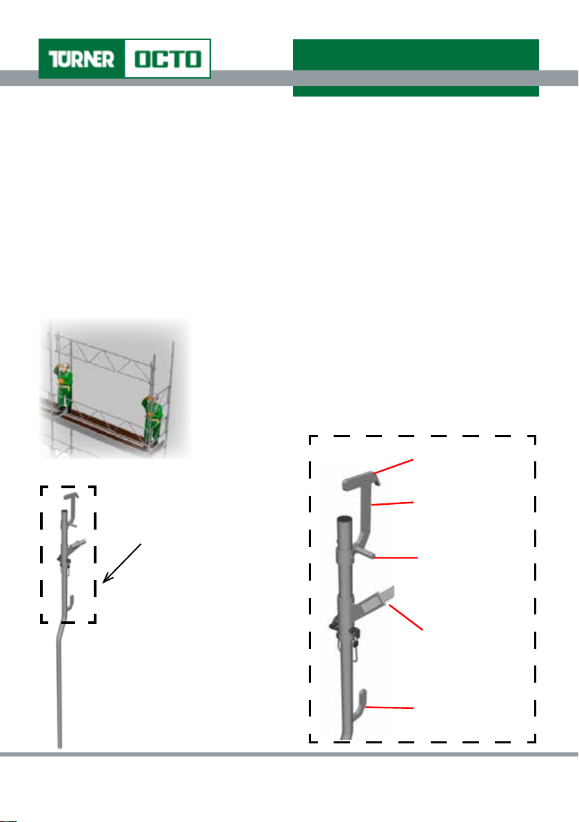
(i) User Instructions
The GuardAid® Positional Tool (Figure 1) provides the scaffolder with integrated safety and
safe systems of work throughout scaffold assembly, dismantle and alteration; therefore,
eliminating the risk of fall from height and enabling compliance with current legislation.
GuardAid® is a scaffold tool used to position, while holding secure, a scaffolding guardrail,
before it is xed and locked into place.
GuardAid® enables existing components to be utilised as integral advance guardrails. This
is achieved by combining a sequence of steps; holding, securing, guiding and then enabling
automatic positioning, xing and locking the existing scaffold component.
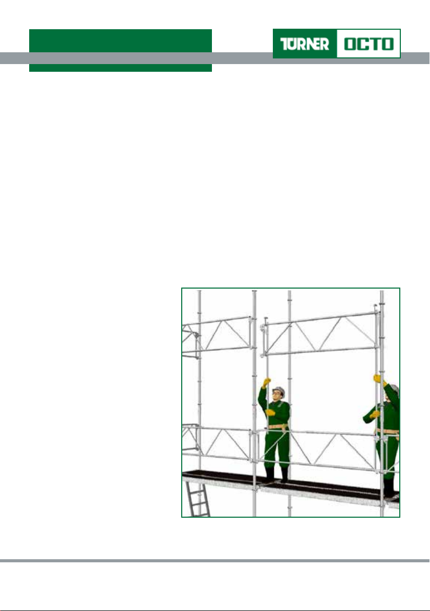
To use the GuardAid® Positional Tool safely, each guardrail
component can be lifted into position by two operatives (one
at each end of the guardrail - as illustrated opposite).
The GuardAid
®
Positional Tool consists of various component
parts within the Tool Head (Detail ‘A’) that have different
functions for the scaffolder using the tool.
Detail ‘A’
Detail ‘A’
GuardAid® Positional Tool
Head
Figure 1 - GuardAid® Positional Tool
©Turner Access Ltd 65 Craigton Road, Glasgow, G51 3EQ, Scotland
Standard Cup Hook
Upper Chord Locator
Locking Pin for
Guardrail Wedge
Guardrail Wedge
Release
Lower Chord
Locator
Section 1 Page 12 TA3/01/50/01_Iss1Rev3
Rev.No.Jan17/Rev3
Page 13
Turner OCTO® Assembly Guide
SECTION 1.4 Safety Information
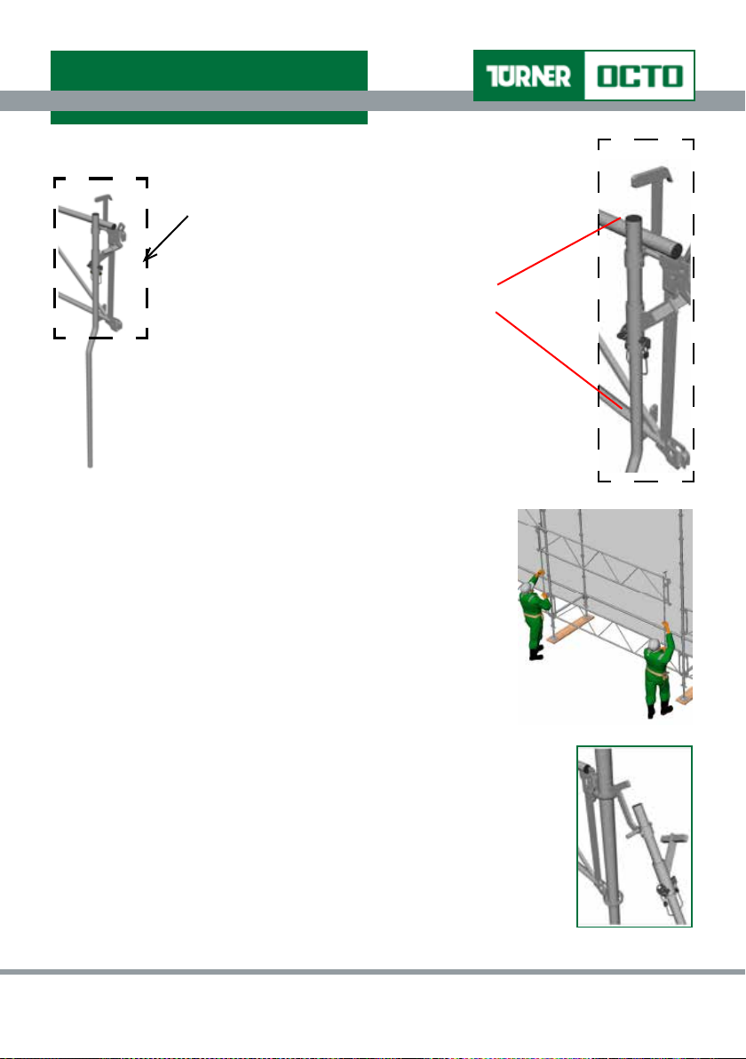
Upper and Lower Chord Locators
Detail ‘B’
Each operative must locate the guardrail
correctly (Figure 2) and ensure it is “seated”
properly in the Upper and Lower chord
locators of the GuardAid
Figure 2 - Using GuardAid
Positional Tool
®
®
tool (Detail B).
Detail ‘B’ - GuardAid®
Positional Tool Head
The operatives should then simultaneously raise the guardrail
and t the guardrail into the cups of the standard.
Detail ‘B’
Standard Cup Hook
Should the scaffold standards be slightly off the plumb then one
operative should locate one end of the guardrail into position
and locate in cups allowing wedge to drop and become loosely
engaged. This operative can then assist in locating the opposite
end of guardrail by using the Standard cup hook (of the GuardAid®
Tool) pulling the standard to the vertical (Figure 3); therefore,
allowing the guardrail to be tted correctly.
Figure 3 - Using Standard Cup Hook
T: +44 (0) 141 309 5555 F: +44 (0) 141 309 5436 www.turner-octo.com
Section 1 Page 13 TA3/01/50/01_Iss1Rev3
Rev.No.Jan17/Rev3
Page 14
Turner OCTO® Assembly Guide
SECTION 1.4 Safety Information
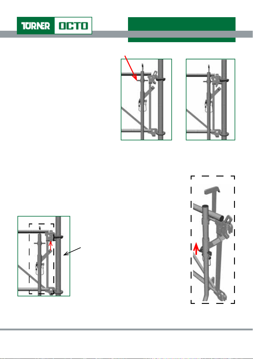
Locking Pin for Guardrail Wedge
Locking Pin for Guardrail Wedge
Using the Guardrail Wedge Locking
Pin, push the wedge from its preset
condition (Figure 4) to the vertical
position and allow to drop and loosely
engage (Figure 5).
When all guardrails (including end
guardrails) are located in position on
the lift and platforms are placed and
locked then the scaffold operatives
should safely access the platform and
drive wedges home on all guardrails.
Guardrail Preset Condition
Figure 4 -
Guardrail loosely engaged
Guardrail Wedge Release
To de-mount the scaffold guardrails each operative must ensure that
the GuardAid® Positional Tool is located correctly in the guardrail prior
to it being removed.
It is then necessary for each operative to
drive the wedges on each end of the guardrail
vertically upwards to loosen (Figure 6).
Figure 5 -
Detail ‘C’
Detail ‘C’
This should be done using
the Guardrail Wedge Release
component part of the GuardAid
tool (Detail ‘C’)
Lift the wedge clear and rest the
wedge on inner ledge within the
guardrail and then both operatives
should simultaneously lift the
Figure 6 - De-Mounting Guardrail
using GuardAid® Positional Tool
©Turner Access Ltd 65 Craigton Road, Glasgow, G51 3EQ, Scotland
Guardrail clear of cups.
®
Detail ‘C’ - De-Mounting Guardrail
using GuardAid® Positional Tool
Section 1 Page 14 TA3/01/50/01_Iss1Rev3
Rev.No.Jan17/Rev3
Page 15
Turner OCTO® Assembly Guide
SECTION 1.4 Safety Information
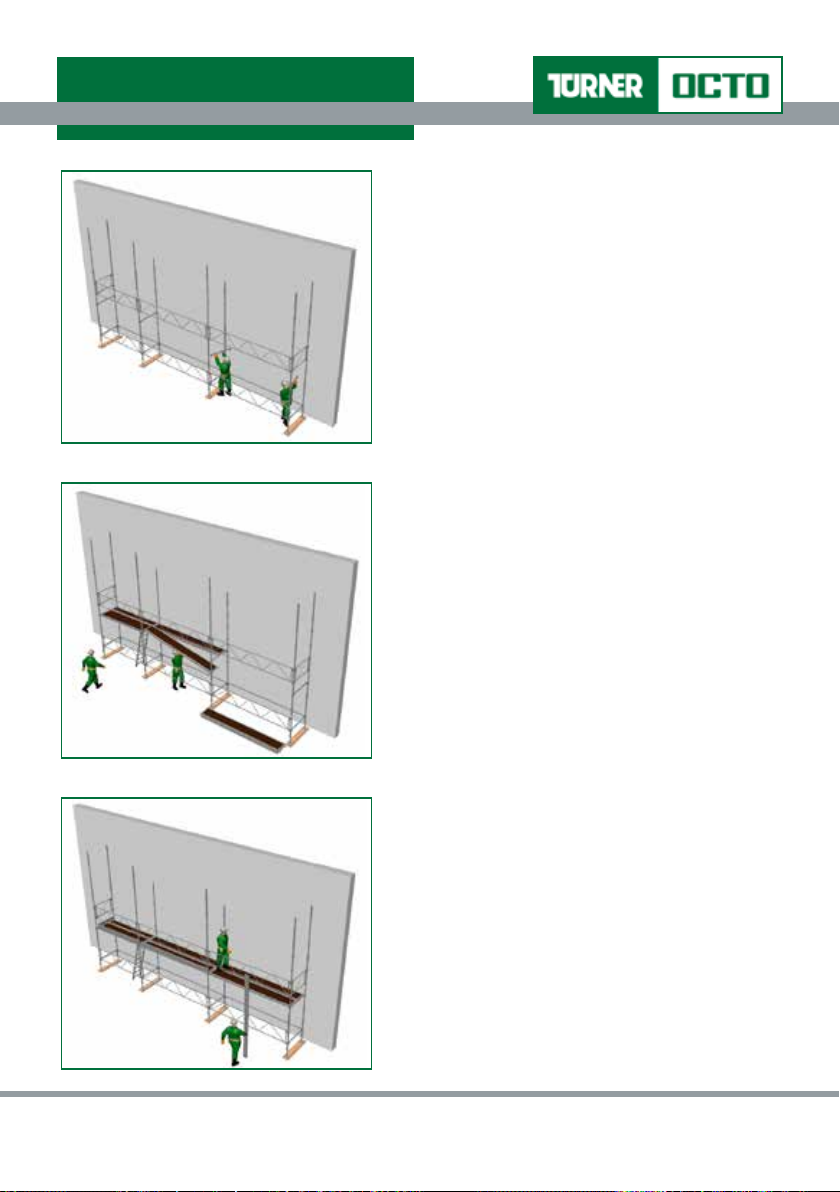
(ii) Wall Scaffold Assembly Procedure using GuardAid
®
This section shows the assembly procedure for a fully boarded tied wall scaffold using
the GuardAid® Positioning Tool; Turner’s recommended system of work for safe scaffold
assembly, dismantle and alteration.
Prior to the commencement of any scaffolding operations appropriate training is recommended.
Forward planning and organisation to ensure the amount and best utilisation of the correct
materials, before assembly procedures commence, will be rewarded throughout assembly
and in the nal scaffold constructed. Please refer to Section 1.5 Assembly Procedures for
further details.
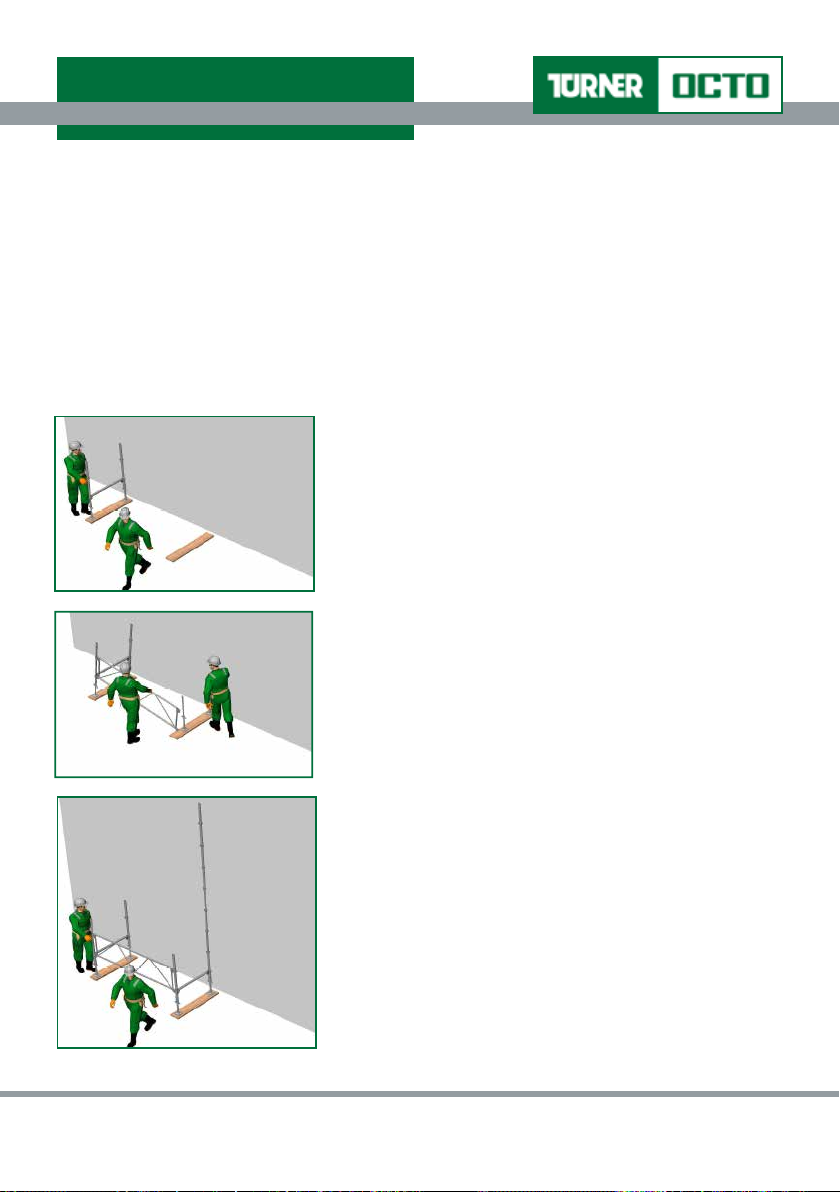
1. Position two Jacks to approximate starting position
of rst bay (on base boards if required) and place
rst pair of appropriate Standards on Jacks then
connect transom (Horizontal) in lowest cups.
2. On outer Standard x Bracing Guardrail (to suit
required bay length) in direction of the length of the
scaffold.
3. Position next pair of Jacks and place Standard
on outer Jack. Connect Bracing Guardrail and x
transom to bottom cup.
4. Place appropriate inner Standard and connect
transom between Standards.
T: +44 (0) 141 309 5555 F: +44 (0) 141 309 5436 www.turner-octo.com
Section 1 Page 15 TA3/01/50/01_Iss1Rev3
Rev.No.Jan17/Rev3
Page 16
Turner OCTO® Assembly Guide
SECTION 1.4 Safety Information
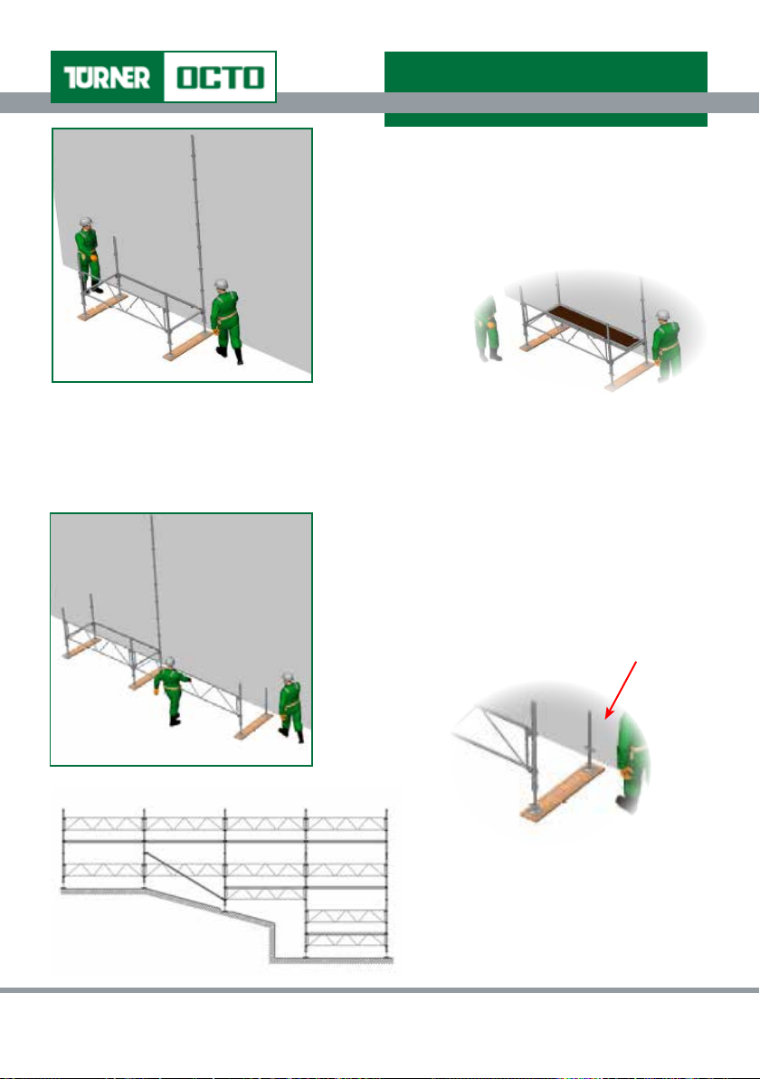
5. Fit Horizontal (ledger) between the inner
Standards (along length of bay) in bottom cups.
6. Check levels along 1st transom, ledger and nally
2nd transom and check that bay is square.
Note It may be advantageous to place a Deck in the bay to assist in “squaring” the bay. Place
an appropriate-sized Deck in the bay against the inside Horizontal (it should be parallel).
If required, make any adjustments and repeat as necessary.
7. Fix required Bracing Guardrail to outer Standard
and leave to “hang” in direction of length of
scaffold.
8. Place next Standard on Jack (set to minimum
height), lift into position and connect Guardrail.
Adjust Jack to sit under Standard.
Note On sloping ground, steps should
be cut to ensure the base boards lie at
and level.
©Turner Access Ltd 65 Craigton Road, Glasgow, G51 3EQ, Scotland
Section 1 Page 16 TA3/01/50/01_Iss1Rev3
Rev.No.Jan17/Rev3
Page 17
Turner OCTO® Assembly Guide
SECTION 1.4 Safety Information
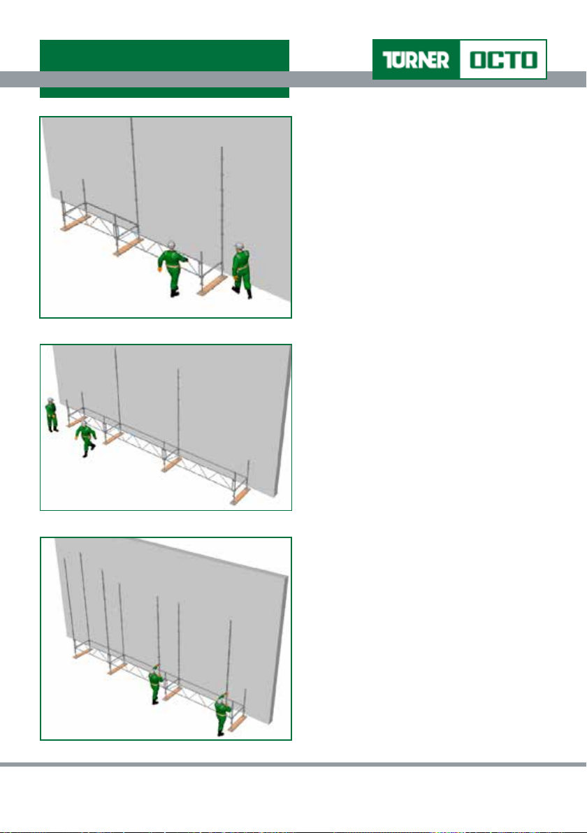
9. Fix transom to outer Standard then
place inner Standard on Jack, lift into
position and connect transom.
10. Fix ledger to inner Standards (bottom
cup) and level. Level along transom.
Repeat steps 7 to 10 until the desired
base length is complete.
Note Ensure that the entire base is
level and square. This will assist greatly
throughout the assembly of the remainder
of the structure.
11. Add additional and appropriate
T: +44 (0) 141 309 5555 F: +44 (0) 141 309 5436 www.turner-octo.com
Standards on top of outer
Standards.
Section 1 Page 17 TA3/01/50/01_Iss1Rev3
Rev.No.Jan17/Rev3
Page 18
Turner OCTO® Assembly Guide
SECTION 1.4 Safety Information
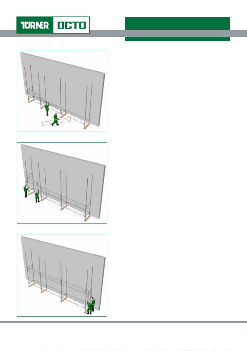
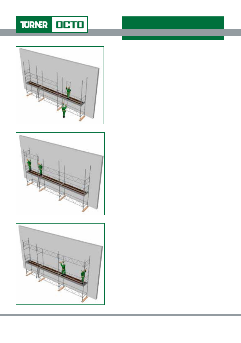
12. Place next lift Guardrails temporarily in cups
immediately above existing base Guardrails.
13. Using GuardAid® Positional Tool, raise
temporary Guardrails (placed at step 12)
into position to suit next lift platform and x
in position.
14. Continue to raise Guardrails from temporary
location into appropriate position to suit rst
lift platform using GuardAid
lift Guardrails are afxed.
©Turner Access Ltd 65 Craigton Road, Glasgow, G51 3EQ, Scotland
®
until entire next
Section 1 Page 18 TA3/01/50/01_Iss1Rev3
Rev.No.Jan17/Rev3
Page 19
Turner OCTO® Assembly Guide
SECTION 1.4 Safety Information
15. Fix transoms at rst lift level (normally 4th
cup).
16. Select appropriate Decks and deck out
transoms (from below) until the lift is
complete (ensuring that locks on each end of
each Deck are in the locked position).
Note Place ladder access unit in one of the
bays to allow access to next lift.
17. Utilising ladder access unit, access can be
gained to Deck level and x Toeboards in
place.
Note Ensure that trapdoor is closed when
working on Deck.
T: +44 (0) 141 309 5555 F: +44 (0) 141 309 5436 www.turner-octo.com
Section 1 Page 19 TA3/01/50/01_Iss1Rev3
Rev.No.Jan17/Rev3
Page 20
Turner OCTO® Assembly Guide
SECTION 1.4 Safety Information
18. Place next lift Guardrails temporarily in cups
immediately above existing Deck Guardrails
and engage Wedge.
19. Using GuardAid® Positional Tool, raise
temporary Guardrails (step 18) into position
to suit next deck lift and x in position.
20. Continue to raise Guardrails into appropriate
position using GuardAid
Guardrails are afxed.
21. Fix transoms at rst lift level (normally 4th
cup from lower deck).
©Turner Access Ltd 65 Craigton Road, Glasgow, G51 3EQ, Scotland
®
until entire next lift
Section 1 Page 20 TA3/01/50/01_Iss1Rev3
Rev.No.Jan17/Rev3
Page 21

Turner OCTO® Assembly Guide
SECTION 1.4 Safety Information
22. Select appropriate Decks and deck out
transoms (from below) until the lift is
complete (ensuring that locks on each
end of each Deck are in the locked
position).
Note Place ladder access unit in one of
the bays to allow access to next lift.
23. Utilising ladder access unit, access can
be gained to Deck level and x Toeboards
in place.
Note Ensure that trapdoor is closed when
working on platform.
24. Add additional and appropriate Standards
on top of inner and outer Standards (if
required).
25. Place next lift Guardrails temporarily in
cups immediately above existing deck
Guardrails and engage Wedge.
26. Using GuardAid® Positional Tool, raise
temporary Guardrails (step 24) into
position to suit next lift platform and x in
position and engage Wedge.
T: +44 (0) 141 309 5555 F: +44 (0) 141 309 5436 www.turner-octo.com
Section 1 Page 21 TA3/01/50/01_Iss1Rev3
Rev.No.Jan17/Rev3
Page 22

Turner OCTO® Assembly Guide
SECTION 1.4 Safety Information
27. Continue to raise Guardrails into appropriate
position using GuardAid® until entire next lift
Guardrails are afxed.
28. Fix transoms at rst lift level (normally 4th
cup from lower platform).
29. Select appropriate Decks and deck out
transoms (from below) until the lift is
complete (ensuring that locks on each end
of each Deck are in the locked position).
Note Place ladder access unit in one of the
bays to allow access to next lift.
30. Utilising ladder access unit, access can be
gained to deck level and x Toeboards in
place.
Note Ensure that trapdoor is closed when
working on Deck.
Repeat steps 24 to 30 until desired platform
height is reached.
©Turner Access Ltd 65 Craigton Road, Glasgow, G51 3EQ, Scotland
Section 1 Page 22 TA3/01/50/01_Iss1Rev3
Rev.No.Jan17/Rev3
Page 23

Turner OCTO® Assembly Guide
SECTION 1.4 Safety Information
1.4.3 Fall Arrest
If lanyards are to be used in the installation of Turner OCTO
®
System Scaffolds, rather than
Turner best and recommended practice using GuardAid®, then double lanyards must be
used.
The attachment points shown below must be used. Only use the specified attachment points.
At no point in the installation should you attach the lanyard to Guardrails or Horizontals. The
positions indicated below are shown and numbered for maximum resistance against fall.
Connections
1 - 6 On the vertical Standard directly above the decked level
on the inside or outside face of the scaffold
7 - 9 On the vertical Standard 1.0m above the deck (2nd cup
above deck level) on the outside face only
10 & 11 On the vertical Standard at 2.0m above working deck
(4th cup above deck level) but ONLY when a transverse
horizontal has been installed beforehand as shown in
diagram above
T: +44 (0) 141 309 5555 F: +44 (0) 141 309 5436 www.turner-octo.com
Section 1 Page 23 TA3/01/50/01_Iss1Rev3
Rev.No.Jan17/Rev3
Page 24

Turner OCTO® Assembly Guide
SECTION 1.5 Assembly Procedures
1.5 ASSEMBLY PROCEDURES FOR TURNER OCTO® SYSTEM SCAFFOLDS
Read this section in conjunction with Section 1.4.1 General Safety Notes on Page 11.
Prior to the commencement of any scaffolding operations appropriate training is recommended.
Forward planning and organisation to ensure the amount and best utilisation of the correct
materials, before assembly procedures commence, will be rewarded throughout assembly
and in the nal scaffold constructed. Careful consideration of the scaffold to be assembled
is required to ensure that it will meet working requirements and is designed to carry the
necessary loads.
The scaffold and the system of work chosen to assemble, dismantle and alter it, must also
comply with the requirements of current legislation, and further ensure that members of the
public are not put at risk.
It is necessary to erect Exclusion Zones and t Warning Signs prior to scaffold assembly.
Ensure the scaffolding is to be assembled on suitable foundations capable of withstanding
the loads imposed by the scaffolding and, where appropriate, adequate base boards to be
provided.
Where the foundation is a soft ground, the soil should be excavated to a rm base or,
alternatively, a larger base board used.
On sloping ground, steps should be cut to ensure the base boards lie at and level.
All components, including GuardAid® components (if used), should be available and
operational.
All components should be closely inspected before use (see Section 1.2 Pre-Use Inspection
& Selection page 5).
Ties should be xed as the scaffold rises (see Tie Pattern on Page 55).
Suitable access should also be used to achieve safe assembly and dismantling at all times.
This Assembly Guide should be issued to all operatives that will assemble, dismantle or alter
Turner OCTO® scaffolds and referred to if required.
Where this symbol appears, a risk of fall is present. However, this is only
applicable if using fall arrest equipment (does not apply when using GuardAid®
methodology to provide collective protection measures).
©Turner Access Ltd 65 Craigton Road, Glasgow, G51 3EQ, Scotland
Section 1 Page 24 TA3/01/50/01_Iss1Rev3
Rev.No.Jan17/Rev3
Page 25

Turner OCTO® Assembly Guide
SECTION 1.5 Assembly Procedures
1.5.1 Tied Wall Scaffold
Prior to the commencement of any scaffolding operations, please refer to Sections 1.4.1
General Safety Notes and 1.5 Assembly Procedures.
(i) Fully Boarded
1. Position two Jacks to approximate
starting position of rst bay (on base
boards if required) and place 1st pair
of appropriate Standards on Jacks.
2. On outer Standard x Bracing
Guardrail (to suit required bay
length) in direction of the length of
the scaffold.
Connect transom (Horizontal) in
lowest cups.
3. Position next pair of Jacks and place
5. Fit Horizontal (ledger) between the
Standard on outerJack, connect
Bracing Guardrail and x transom to
bottom cup.
6. Check levels along 1st transom,
4. Place appropriate inner Standard
and connect transom between
Standards.
T: +44 (0) 141 309 5555 F: +44 (0) 141 309 5436 www.turner-octo.com
inner Standards (along length of
bay) in bottom cups.
ledger and nally 2nd transom and
check that bay is square.
Section 1 Page 25 TA3/01/50/01_Iss1Rev3
Rev.No.Jan17/Rev3
Page 26

Turner OCTO® Assembly Guide
SECTION 1.5 Assembly Procedures
Note It may be advantageous to place a
Deck in the bay to assist in “squaring” the
bay. Place an appropriate sized Deck in the
bay against the inside Horizontal (it should
be parallel).
If required, make any adjustments and
repeat as necessary.
9. Fix transom to outer Standard then place
inner Standard on Jack, lift into position
and connect transom.
10. Fix ledger to inner Standards (bottom
cup) and level. Level along transom.
Repeat steps 7 to 10 until the desired base
length is complete.
7. Fix required Guardrail to outer
Standard and leave to “hang” in
direction of length of scaffold.
8. Place next Standard on Jack (set to
minimum height), lift into position and
connect Guardrail. Adjust Jack to seat
under Standard.
Note Ensure that the entire base is
level and square. This will assist greatly
throughout the assembly of the remainder
of the structure.
11. Add additional and appropriate
Standards on top of outer Standards.
©Turner Access Ltd 65 Craigton Road, Glasgow, G51 3EQ, Scotland
Section 1 Page 26 TA3/01/50/01_Iss1Rev3
Rev.No.Jan17/Rev3
Page 27

Turner OCTO® Assembly Guide
SECTION 1.5 Assembly Procedures
Note Ensure that the entire base is level
and square before proceeding with rst
lift height.
13. Add additional and appropriate-sized
Standards on top of the existing
outer Standards (as necessary)
to allow placing of the next lift of
scaffolding.
12. Place appropriate-sized Decks,
Bracing Guardrails and all
Horizontals to complete rst lift
safely. Ensure that ladder access
unit is situated in one of the bays to
allow access to next lift.
14. Repeat placement of appropriatesized Decks, Bracing Guardrails,
Horizontals and ladder access unit to
complete the second lift.
T: +44 (0) 141 309 5555 F: +44 (0) 141 309 5436 www.turner-octo.com
Section 1 Page 27 TA3/01/50/01_Iss1Rev3
Rev.No.Jan17/Rev3
Page 28

Turner OCTO® Assembly Guide
SECTION 1.5 Assembly Procedures
15. Position inner Standards as
necessary and continue to next lift.
17. Fit Toeboards to each working lift.
16. Repeat sequence until desired
height is reached.
18. Completed scaffold.
©Turner Access Ltd 65 Craigton Road, Glasgow, G51 3EQ, Scotland
Section 1 Page 28 TA3/01/50/01_Iss1Rev3
Rev.No.Jan17/Rev3
Page 29

Turner OCTO® Assembly Guide
SECTION 1.5 Assembly Procedures
(ii) Top Lift
Prior to the commencement of any scaffolding operations, please refer to Sections 1.4.1
General Safety Notes and 1.5 Assembly Procedures.
To assemble top lift only scaffolds, simply remove Decks from the bays that do not require
to have a working platform below the top lift (leaving ladder access bay in place).
1. Add Bracing Guardrails between
outer and inner Standards to provide
2. Remove Decks from the remaining
bays (from below).
protection to the ladder access bay
prior to removing Decks.
3. Fit Toeboards. 4. Completed scaffold.
T: +44 (0) 141 309 5555 F: +44 (0) 141 309 5436 www.turner-octo.com
Section 1 Page 29 TA3/01/50/01_Iss1Rev3
Rev.No.Jan17/Rev3
Page 30

Turner OCTO® Assembly Guide
SECTION 1.5 Assembly Procedures
(iii) Corner Returns
External / Internal
Construction of the scaffold structure with corner returns should begin at a corner of the
building allowing for either corner return options 1 to 3 to be built correctly. Option 4 return
may be required in a corner to complete the scaffold run.
Option 1: 3 Legged Return
External
Constructed using 3 legs built
from base level.
Internal
©Turner Access Ltd 65 Craigton Road, Glasgow, G51 3EQ, Scotland
Section 1 Page 30 TA3/01/50/01_Iss1Rev3
Rev.No.Jan17/Rev3
Page 31

Turner OCTO® Assembly Guide
SECTION 1.5 Assembly Procedures
Option 2: 4 Legged (core) Return
External
Built from a complete bay of scaffold where inside Standard is placed at corner and a run
of scaffold is constructed in both direction away from the corner along the building façade.
Internal
T: +44 (0) 141 309 5555 F: +44 (0) 141 309 5436 www.turner-octo.com
Section 1 Page 31 TA3/01/50/01_Iss1Rev3
Rev.No.Jan17/Rev3
Page 32

Turner OCTO® Assembly Guide
SECTION 1.5 Assembly Procedures
Option 3: Corner Return with inside boards
External
Two runs of scaffolding linked by a bay at the corner identical in size to the inside boards
allowing for Decks to be placed from the bay in one direction and placed on inside Cantilever
Brackets in the other direction. This allows for movement of the inside boards without
interfering with the scaffold construction.
Internal
©Turner Access Ltd 65 Craigton Road, Glasgow, G51 3EQ, Scotland
Section 1 Page 32 TA3/01/50/01_Iss1Rev3
Rev.No.Jan17/Rev3
Page 33

Turner OCTO® Assembly Guide
SECTION 1.5 Assembly Procedures
Option 4: Fly By Return
Two runs of scaffolding that meet at a corner but cannot form one of the returns as shown
previously. Therefore, it is necessary to let one scaffold “y by” the other to maintain scaffold
run platform width. It will be necessary to close the gap with handrailing and Toeboards to
protect users.
In all cases, ensure that Bracing Guardrails are tted on inside faces of the scaffold
structure if the gap between the building and the scaffold structure exceeds 225mm (or local
regulations, if different).
T: +44 (0) 141 309 5555 F: +44 (0) 141 309 5436 www.turner-octo.com
Section 1 Page 33 TA3/01/50/01_Iss1Rev3
Rev.No.Jan17/Rev3
Page 34

Turner OCTO® Assembly Guide
SECTION 1.5 Assembly Procedures
1.5.2 Independent Towers
Prior to the commencement of any scaffolding operations,
please refer to Sections 1.4.1 General Safety Notes and 1.5
Assembly Procedures.
(i) Fully Boarded
1. Base out structure
according to base out
procedure in Section 1.5.1
Tied Wall Scaffold Fully
Boarded steps 1 to 11.
Note Ensure that the entire
base is level and square before
proceeding with rst lift height.
2. Place appropriate-sized
Decks (incl. ladder unit
to one side of tower),
Bracing Guardrails
and all Horizontals to
complete rst lift safely.
4. Repeat placement of appropriate-sized
Decks, ladder access, Bracing Guardrails &
Horizontals to complete subsequent lifts.
5. Fit Toeboards.
3. Add additional and
appropriate-sized
Standards on top of
existing Standards to
allow placing of the next
lift of scaffolding.
6. Completed
Scaffold.
©Turner Access Ltd 65 Craigton Road, Glasgow, G51 3EQ, Scotland
Section 1 Page 34 TA3/01/50/01_Iss1Rev3
Rev.No.Jan17/Rev3
Page 35

Turner OCTO® Assembly Guide
SECTION 1.5 Assembly Procedures
(ii) Top Lift
Prior to the commencement of any scaffolding operations, please refer to Sections 1.4.1
General Safety Notes and 1.5 Assembly Procedures.
1. Add Bracing Guardrails between
outer and inner Standards to provide
protection to the ladder access bay
2. Using Bracing Guardrail to Bracing Guardrail
Connector component, close off ladder
access units leaving them safe to use.
prior to removing decks.
3. Fit toeboards.
T: +44 (0) 141 309 5555 F: +44 (0) 141 309 5436 www.turner-octo.com
Section 1 Page 35 TA3/01/50/01_Iss1Rev3
Rev.No.Jan17/Rev3
Page 36

Turner OCTO® Assembly Guide
SECTION 1.5 Assembly Procedures
(iii) Mobile
Prior to the commencement of any scaffolding operations, please refer to Sections 1.4.1
General Safety Notes and 1.5 Assembly Procedures.
The following drawings show the base out procedure for a mobile tower. On completion of
the base out, proceed using steps 2 - 6 on Page 34.
1. Position four Castor
Wheel Jacks and
four Horizontals to
approximate starting
position of rst bay.
4. Place third Standard on
Jack and connect third
2. Ensure wheels are
locked, then place rst
Standard on Jack and
connect Horizontal in
3. Place second Standard
on Jack and connect
second Horizontal in
lowest cup.
lowest cup.
5. Continue until all Horizontals are connected. Check
levels along Horizontals and check that bay is square.
Horizontal in lowest cup.
Note Please refer to the Inspection & Maintenance Guidance Notes for Mobile Structures
on Page 37 when moving Turner OCTO
©Turner Access Ltd 65 Craigton Road, Glasgow, G51 3EQ, Scotland
®
scaffold structures.
Section 1 Page 36 TA3/01/50/01_Iss1Rev3
Rev.No.Jan17/Rev3
Page 37

Turner OCTO® Assembly Guide
SECTION 1.5 Assembly Procedures
(iv) Inspection & Maintenance Guidance Notes for Mobile Structures
All mobile structures should be inspected prior to any moves to determine the integrity of the
structures has not been compromised. All components should be securely fastened.
Upon completion of your operations, all tools, materials, debris, etc. should be removed
and all platforms left in this condition. Before usage of structure and prior to structure being
moved, all platforms should be checked to ensure that they are free of any loose items.
All personnel should be clear of structure prior to movement of that structure. However, if
it has been determined by the person in charge that it will be necessary to have personnel
on board the structure to assist in the safe passage of the structure then the following is
necessary:-
i. Check with Turner OCTO® Design Dept. to ensure that personnel can be positioned on
board the structure.
If Item (i) has been afrmed then temporary guardrails have to be placed in position to
protect those on board when the structure is moved.
It is absolutely necessary to ensure that brake locks are in the off position during all
movements of the structure to avoid unnecessary damage occurring to the Castor wheel
and Jack arrangements or “at spots” appearing on the wheel.
When the structure has been successfully moved to its required location, and is stationary,
all brake locks must be on.
Protruding items are potentially hazardous and may cause injury to personnel or damage to
surrounding areas. To prevent such incidents occurring all protrusions should be removed, if
possible, or protective measures deployed before movement of structure.
If structure is to be stored outside, said structure should be adjoined to other such structures
in storage area to add stability and suitable anchorage / ties utilised to prevent overturn
or movement due to prevailing weather conditions. Deck locks should be on and further
supplemented by other means such as cable ties especially if exposed conditions are
expected.
When structure is stored and not in use, access to the structure should be restricted by any
means necessary at all access points on all structure.
T: +44 (0) 141 309 5555 F: +44 (0) 141 309 5436 www.turner-octo.com
Section 1 Page 37 TA3/01/50/01_Iss1Rev3
Rev.No.Jan17/Rev3
Page 38

Turner OCTO® Assembly Guide
SECTION 1.5 Assembly Procedures
The following checks and procedures must be followed prior to and during all moves (refer
to Guidance notes):
TICK
( ) All structures and components are securely in place.
( ) All platforms have been checked and are clear of any debris and / or all loose items.
( ) All personnel are cleared from structure to be moved.
If it has been deemed necessary by the Client that personnel are required to be stationed
on board the structure to provide guidance whilst it is being moved then the following
checks are to be included.
( ) Design check has been requested.
( ) Temporary guardrails are in position.
( ) All brake locks are off prior to and during all movements of structure.
( ) All brake locks are on when structure is stationary and in required position (location).
( ) All protruding items are removed or protective measures deployed.
( ) Is structure to be stored outside?
If yes;
( ) All necessary measures have been taken to prevent movement when stored.
( ) All access to structure has been restricted when stored.
Signed…………………………………………. Date…………………
©Turner Access Ltd 65 Craigton Road, Glasgow, G51 3EQ, Scotland
Section 1 Page 38 TA3/01/50/01_Iss1Rev3
Rev.No.Jan17/Rev3
Page 39

Turner OCTO® Assembly Guide
SECTION 1.5 Assembly Procedures
1.5.3 Birdcages
A Turner OCTO® system birdcage scaffold creates a large at platform that can cover a great
expanse of work area overhead.
The procedure for assembling the birdcage is similar to building a series of towers. Each
tower is constructed from the tower next to it.
Prior to the commencement of any scaffolding operations, please refer to Sections 1.4.1
General Safety Notes and 1.5 Assembly Procedures.
1. Base out structure according to base
out procedure in Section 1.5.1 Tied
Wall Scaffold Fully Boarded steps 1
to 11.
Note Ensure that the entire base is level
and square before proceeding with rst
lift height. It may be advantageous to t
temporary bracing guardrails to determine the
positioning of second structure and to assist
in levelling overall structure.
T: +44 (0) 141 309 5555 F: +44 (0) 141 309 5436 www.turner-octo.com
2. Place appropriate-sized Decks,
Bracing Guardrails, Horizontals and
Standards to complete each lift.
3. Repeat sequence until desired height
is reached.
4. Fit Toeboards to working lift.
Completed Scaffold.
Section 1 Page 39 TA3/01/50/01_Iss1Rev3
Rev.No.Jan17/Rev3
Page 40

Turner OCTO® Assembly Guide
SECTION 1.5 Assembly Procedures
To assemble top lift only birdcage scaffolds,
remove Decks from the bays that do not
require to have a working platform below the
top lift (leaving ladder access bay in place).
Add Bracing Guardrails between outer and
inner Standards to provide protection to the
ladder access bay prior to removing Decks.
Remove Decks from the remaining bays
(from below).
Fit Toeboards.
(i) Linked Birdcage
Birdcage scaffolds can also be constructed by linking 2 runs of scaffolding using Bracing
Guardrails as the assembly procedure progresses until nal lift height is achieved and the
full platform is completed.
The bay sizes and links can be
any OCTO® system modular
size from 0.7m to 3.5m.
Bay Length / Width ‘x-x’ = 0.70m to 3.50m
©Turner Access Ltd 65 Craigton Road, Glasgow, G51 3EQ, Scotland
Section 1 Page 40 TA3/01/50/01_Iss1Rev3
Rev.No.Jan17/Rev3
Page 41

Turner OCTO® Assembly Guide
SECTION 1.5 Assembly Procedures
1. Base out structure according to base
out procedure in Section 1.5.1 Tied Wall
Scaffold Fully Boarded steps 1 to 11.
2. Fit temporary Bracing Guardrails to
protect the scaffold run platforms when
working from them. Bracing Guardrails
should be used to create the link between
the scaffold runs.
Note Ensure that the entire base is level and
square before proceeding with rst lift height. It
may be advantageous to t temporary Bracing
Guardrails to determine the positioning of second
structure and to assist in levelling overall structure.
3. Place appropriate-sized Decks, Bracing
4. Fit Toeboards to each working lift.
Guardrails, and Horizontals to complete
rst (ladder access unit) lift safely.
To assemble top lift only birdcage scaffolds, remove Decks
from the bays that do not require a working platform below
the top lift (leaving ladder access bay in place).
Add Bracing Guardrails between outer and inner Standards
to provide protection to the ladder access bay prior to
removing Decks. Remove Decks from the remaining bays
(from below). Fit Toeboards.
T: +44 (0) 141 309 5555 F: +44 (0) 141 309 5436 www.turner-octo.com
Section 1 Page 41 TA3/01/50/01_Iss1Rev3
Rev.No.Jan17/Rev3
Page 42

Turner OCTO® Assembly Guide
SECTION 1.5 Assembly Procedures
1.5.4 Freestanding Structures
The stability of freestanding structures is created using buttressing.
The example below is formed using full box type buttressing extended to the lift below the
full height of the structure (platform level) and tied back to the wall scaffold using plan braces
enabling each leg of the wall scaffold to be connected to the buttress.
This type of buttress provides the greatest stability to the wall scaffold structure.
Prior to the commencement of any scaffolding operations, please refer to Sections 1.4.1
General Safety Notes and 1.5 Assembly Procedures.
For freestanding structures ensure all standards are pinned (using Standard Pins).
1. Base out wall scaffold to 1st lift height
3. Position Jacks to approximate starting
according to base out procedure in
Section 1.5.1 Tied Wall Scaffold Fully
Boarded steps 1 to 11.
2. Determine correct positioning for
buttress and x bracing guardrails (to
suit correct size of buttress) from outer
4. Fit plan bracing from buttress Standard
Standards and leave to “hang” in the
direction of buttress.
©Turner Access Ltd 65 Craigton Road, Glasgow, G51 3EQ, Scotland
position of rst bay (on base boards
if required) and place rst pair of
appropriate standards on Jacks then
connect transom (horizontal) in lowest
cups.
to tie back to wall scaffold and afx to
wall scaffold (in cup).
Section 1 Page 42 TA3/01/50/01_Iss1Rev3
Rev.No.Jan17/Rev3
Page 43

Turner OCTO® Assembly Guide
SECTION 1.5 Assembly Procedures
5. Place appropriate-sized Decks (incl.
ladder unit to one side of tower),
Bracing Guardrails and all Horizontals
to complete rst lift safely.
8. Repeat placement of appropriate-sized
Decks, ladder access, Bracing Guardrails
and Horizontals to complete subsequent
lifts of the buttress.
6. Add additional and appropriatesized Standards on top of existing
Standards to allow placing of next lift
of scaffolding.
7. Fix bracing guardrails and plan
bracing from buttress standard to tie
back to wall scaffold and afx to wall
scaffold (in cup).
9. Completed scaffold.
T: +44 (0) 141 309 5555 F: +44 (0) 141 309 5436 www.turner-octo.com
Section 1 Page 43 TA3/01/50/01_Iss1Rev3
Rev.No.Jan17/Rev3
Page 44

Turner OCTO® Assembly Guide
SECTION 1.5 Assembly Procedures
Buttress Examples
Due to the complexity of any freestanding structure i.e. whether a structure is to be
sheeted or netted; if there is enough space to provide a full buttress, will the structure be
exposed to wind or other such important factors, then the structure may require additional
stability measures (ballast) to be employed and should therefore be designed prior to any
works commencing.
The following examples are illustrative only and may be subject to specic design criteria.
Tower Buttress Examples
Wall Scaffold Buttress Examples
©Turner Access Ltd 65 Craigton Road, Glasgow, G51 3EQ, Scotland
Section 1 Page 44 TA3/01/50/01_Iss1Rev3
Rev.No.Jan17/Rev3
Page 45

Turner OCTO® Assembly Guide
SECTION 1.5 Assembly Procedures
1.5.5 Cantilever Brackets
Prior to the commencement of any scaffolding operations, please refer to Sections 1.4.1
General Safety Notes and 1.5 Assembly Procedures.
(i) Inside Boards
1. Base out structure according to base
out procedure in Section 1.5.1 Tied Wall
Scaffold Fully Boarded steps 1 to 11.
Note Ensure that the entire base is level and
square before proceeding with rst lift height.
3. Add additional and appropriate-sized
Standards on top of the existing outer
Standards (as necessary) to allow
placing of the next lift of scaffolding.
T: +44 (0) 141 309 5555 F: +44 (0) 141 309 5436 www.turner-octo.com
2. Place appropriate-sized Decks,
Bracing Guardrails, Horizontals and
Cantilever Brackets to complete rst
lift safely. Ensure that ladder access
unit is situated in one of the bays to
allow access to next lift.
4. Repeat placement of appropriatesized Decks, Bracing Guardrails,
Horizontals and ladder access unit to
complete the second lift.
Section 1 Page 45 TA3/01/50/01_Iss1Rev3
Rev.No.Jan17/Rev3
Page 46

Turner OCTO® Assembly Guide
SECTION 1.5 Assembly Procedures
5. Position inner Standards as necessary
and continue to next lift.
7. Fit Toeboards to each working lift
(ends at additional inside cantilver
brackets).
6. Repeat sequence until desired height
is reached.
8. Completed scaffold.
Tied Wall Scaffold with Bridge - Example of Cantilever Brackets in use.
©Turner Access Ltd 65 Craigton Road, Glasgow, G51 3EQ, Scotland
Section 1 Page 46 TA3/01/50/01_Iss1Rev3
Rev.No.Jan17/Rev3
Page 47

Turner OCTO® Assembly Guide
SECTION 1.5 Assembly Procedures
(ii) Cantilever Brackets with End Plate
Cantilever brackets with end plate (0.10m to 1.20m) are used as inside cantilever brackets
to minimise the gap between the scaffold structure and the building.
They may also be used (in some instances) as hop up brackets and moved as works
progress.
(iii) Cantilever Brackets with Cup
Cantilever brackets with cup (0.50m to 1.25m) can be used to the inside, outside or end
faces of the scaffold structure.
Additional scaffold materials can be built from this cantilever bracket (in accordance with
design) useful in bridging over lower level projections (for example) or increasing platform
width if necessary in certain applications.
T: +44 (0) 141 309 5555 F: +44 (0) 141 309 5436 www.turner-octo.com
Section 1 Page 47 TA3/01/50/01_Iss1Rev3
Rev.No.Jan17/Rev3
Page 48

Turner OCTO® Assembly Guide
SECTION 1.5 Assembly Procedures
To provide additional loading capacity to the cantilever bracket with cup then the bracket
should be located 0.5m (1 cup in normal circumstances) below the platform level to allow
diagonal face braces to be tted as a raker.
Additional Horizontals (transoms) must be tted below the existing platform adjacent to the
cantilever bracket and also at the lift below where the diagonal face brace ts in the cup.
Note When using this arrangement, refer to design.
©Turner Access Ltd 65 Craigton Road, Glasgow, G51 3EQ, Scotland
Section 1 Page 48 TA3/01/50/01_Iss1Rev3
Rev.No.Jan17/Rev3
Page 49

Turner OCTO® Assembly Guide
SECTION 1.5 Assembly Procedures
1.5.6 Circular Structures
Prior to the commencement of any scaffolding operations, please refer to Sections 1.4.1
General Safety Notes and 1.5 Assembly Procedures.
The circular scaffold structure is a series of towers that are linked together.
1. Base out structure according to base
out procedure in Section 1.5.1 Tied Wall
Scaffold Fully Boarded steps 1 to 11.
2. Ensure that the inside Horizontals
(ledgers) have free passage and do not
foul the structure.
3. Place appropriate sized Decks, Bracing
Guardrails and Horizontals in the towers
(including a ladder access unit in at least
one tower) and link between the towers
(in accordance with the design) ensuring
Bracing Guardrails are tted too.
Should the minimum handrail height fall
below regulated heights then an additional
ledger should be added above the Bracing
Guardrail (handrail).
T: +44 (0) 141 309 5555 F: +44 (0) 141 309 5436 www.turner-octo.com
Section 1 Page 49 TA3/01/50/01_Iss1Rev3
Rev.No.Jan17/Rev3
Page 50

Turner OCTO® Assembly Guide
SECTION 1.5 Assembly Procedures
4. Repeat placement of appropriate-sized
Decks, ladder access units, Bracing
Guardrails and Horizontals to complete
subsequent lifts.
5. Fit Toeboards.
6. Completed Scaffold.
©Turner Access Ltd 65 Craigton Road, Glasgow, G51 3EQ, Scotland
Section 1 Page 50 TA3/01/50/01_Iss1Rev3
Rev.No.Jan17/Rev3
Page 51

Turner OCTO® Assembly Guide
SECTION 1.5 Assembly Procedures
1.5.7 Suspended Scaffolds (Hanging Scaffolds)
Prior to the commencement of any scaffolding operations, please refer to Sections 1.4.1
General Safety Notes and 1.5 Assembly Procedures.
There are many variations in the design and construction of hanging scaffolds. The following
instructions are intended as an example only of one type based on the nal design of the
hanging structure.
All hanging scaffolds are subject to design and verication of that design prior to scaffolding
works commencing.
Note When constructing a hanging scaffold structure you MUST pin the standards using
high tensile M16 Nuts and Bolts.
1. Assemble the tower structure using
additional Base Jacks upturned in the
Standards that can then be adjusted
to t tight against the underside of the
oor above. This provides structural
stability.
This should be carried out in strict
accordance with design drawings and
appropriate plan bracing tted.
T: +44 (0) 141 309 5555 F: +44 (0) 141 309 5436 www.turner-octo.com
2. Fit connecting Horizontals (transoms)
from tower structure to allow connection
of hanging Standards.
3. Fit Guardrails and Horizontals (ledgers)
and tie Standards back to the tower
structure using diagonal face braces
ensuring all components are securely
locked.
4. Fit Decks.
Section 1 Page 51 TA3/01/50/01_Iss1Rev3
Rev.No.Jan17/Rev3
Page 52

Turner OCTO® Assembly Guide
SECTION 1.5 Assembly Procedures
5. Create hanging bay using Standards,
Bracing Guardrails, Horizontals,
Cantilever Brackets and Decks.
6. Tie outside Standards back to tower
structure using diagonal face braces.
7. Fit hanging Standards to complete the
bay and pin using high tensile M16
Nuts and Bolts.
8. Fit appropriate Bracing Guardrails,
Horizontals and Decks to complete
bay.
Ensure that a ladder access unit is tted
to gain access to lower level.
9. Fit Toeboards. 10. Complete Scaffold.
©Turner Access Ltd 65 Craigton Road, Glasgow, G51 3EQ, Scotland
Section 1 Page 52 TA3/01/50/01_Iss1Rev3
Rev.No.Jan17/Rev3
Page 53

Turner OCTO® Assembly Guide
SECTION 1.5 Assembly Procedures
1.5.8 Pre Scaffold Handover Inspection
The scaffold should be visually inspected to make certain that all components used have
been installed correctly and secured to prevent accidental displacement.
Check that all necessary scaffold ties (if required) have been installed in accordance with
the tie pattern on page 55 and that all Guardrails and Toeboards have been tted to the
working platforms.
1.5.9 Maintenance
®
All Turner OCTO
Scaffolds, in common with all types of scaffolding, should be regularly
inspected (at least once per week) and recorded, in accordance with current legislation.
The statutory regulations of each state or country should be observed and/ or the type of
work to be carried out on the scaffolding or the environment in which the scaffolding is to be
used, or the position (if moved) may also determine the frequency of inspections required.
However, it is good safety practice to inspect the structure before every working shift and
any defects or misuse reported and corrected, as soon as possible, by a competent person.
Examples of misuse are as follows (but not limited to):
• Overloading of platforms
• Removal of Components; in particular, decking, guardrails, toeboards and ties
• Undermining of foundations
• Sheeting xed to structure without approval
• Electrical Hazards
T: +44 (0) 141 309 5555 F: +44 (0) 141 309 5436 www.turner-octo.com
Section 1 Page 53 TA3/01/50/01_Iss1Rev3
Rev.No.Jan17/Rev3
Page 54

Turner OCTO® Assembly Guide
SECTION 1.5 Assembly Procedures
1.5.10 Dismantling Procedure
The dismantling procedure should simply be a reversal of the steps explained for the
assembly of the various types of standard congurations.
However, several safety procedural steps should be considered before dismantling
operations begin.
1. Refer to your Risk Assessment – a separate Risk Assessment should be carried out
prior to any dismantling operations.
2. Visually check the scaffold from ground level for any obvious hazards that may have
developed or been created (by the user) that may not be listed on the Risk Assessment.
Such hazards may include:
• Debris left on the scaffold
• Overhead wires on or touching the scaffold
• Obvious removal of scaffold ties (check number of ties tted on Hand Over Certicate to
assist in determining whether ties may have been removed).
• Removal of structurally important components, e.g. Decks and Bracing Guardrails.
This list is not exhaustive and other hazards may exist. If in any doubt and you can see
hazards that have not been notied on the Risk Assessment, seek consultation before
proceeding to the next step.
3. Erect an exclusion zone and t Warning signs in accordance with current legislation
prior to scaffold dismantle taking place.
4. Commence dismantling operations and continue to visually inspect scaffold at close
proximity throughout the dismantling procedure for any unforeseen hazards.
©Turner Access Ltd 65 Craigton Road, Glasgow, G51 3EQ, Scotland
Section 1 Page 54 TA3/01/50/01_Iss1Rev3
Rev.No.Jan17/Rev3
Page 55

Turner OCTO® Assembly Guide
SECTION 1.6 Anchoring
1.6 ANCHORING
1.6.1 Tie Patterns for unclad scaffolds
3500 max. 3500 3500 35003500
200020002000200020002000200020002000200020002000
24000
Denotes Tie Location
4270 max.
Every standard to be tied at top lift except where platform is greater than 1500mm from eaves.
• End ties to be tied at maximum 4000mm crs
• All ties to be within 300mm of standard - transom joint
• Good practice is to x all ties to inner and outer standards. A minimum requirement is for all end ties to be xed to
inner and outer standards and other ties xed to inner standard only.
T: +44 (0) 141 309 5555 F: +44 (0) 141 309 5436 www.turner-octo.com
Section 1 Page 55 TA3/01/50/01_Iss1Rev3
Rev.No.Jan17/Rev3
Page 56

1.6.2 Tie Loads
Turner OCTO® Assembly Guide
SECTION 1.6 Anchoring
Unclad Scaffold 24m x 1m with 0.7m (max) cantilevers; Load Class 3
WIND LOAD CRITERIA
BS EN 12810 - 1 EDGE End standards > 2.0m from edge of building
• South East England EDGE(II) End standards ≤ 2.0m from edge of building
• Distance <100m from sea INTERIOR Any Internal standards
• 300m land altitude TOP Top platform level > 2.0m from eaves of building
• Open Country TOP(II) Top platform level ≤ 2.0m from eaves of building
BS 6999 - 2 EDGE End standards > 2.0m from edge of building
• West of Scotland EDGE(II) End standards ≤ 2.0m from edge of building
• Distance <100m from sea INTERIOR Any Internal standards
• 300m land altitude TOP Top platform level > 2.0m from eaves of building
• Open Country TOP(II) Top platform level ≤ 2.0m from eaves of building
MAXIMUM
TIE LOADS
1000 CB060
DESCRIPTION
1000 CB060 1000 CB060 1000 CB060
CONFIGURATIONS
C1 & C2
(kN)
C3 & C4
(kN)
3.1 2.9
6.2 5.8
5.7 5.6
3.0 3.0
5.6 5.5
4.3 3.9
8.4 7.7
7.6 7.5
4.0 3.8
7.3 7.2
Max. 24.0m
Bracing guardrails & Transoms @ 2.0m c/c
Max. 4.27m to rst Tie Location
C1 C3C2 C4
©Turner Access Ltd 65 Craigton Road, Glasgow, G51 3EQ, Scotland
Section 1 Page 56 TA3/01/50/01_Iss1Rev3
Rev.No.Jan17/Rev3
Page 57

Turner OCTO® Assembly Guide
SECTION 1.7 Maximum Heights
1.7 MAXIMUM HEIGHTS
1.7.1 Assembly Criteria - Unclad Tied Wall Scaffold Examples
FOOT TIED FOOT TIED NON FOOT TIED
COMPONENTS
(Horizontal as
Base Transom
Member)
Max Bay Length 3500mm 3500mm 3500mm
(Guardrail as
Base Transom
Member)
TRANSOMS
LEDGERS
(Inside Face)
GUARDRAILS
(Outside Face)
Max. Height to rst
transom
Max. Subsequent
vertical spacing
Horizontal Spacing In End Bays + minimum every 2nd Bay
Max. Height to rst
ledger
Max. Subsequent
vert. spacing
Horizontal Spacing In End Bays + minimum every 2nd Bay
Max. Height to
bottom chord of 1st
guardrail
Max. Subsequent
vert. Spacing c/c
800mm 800mm 2700mm
2000mm 2000mm 2000mm
800mm 800mm 800mm
2000mm 2000mm 2000mm
Ledgers not required where locked Turner System decks
are in place
800mm 800mm 800mm
2000mm 2000mm 2000mm
T: +44 (0) 141 309 5555 F: +44 (0) 141 309 5436 www.turner-octo.com
Section 1 Page 57 TA3/01/50/01_Iss1Rev3
Rev.No.Jan17/Rev3
Page 58

Turner OCTO® Assembly Guide
SECTION 1.7 Maximum Heights
The following examples of Unclad Tied Wall Scaffolds are SYSTEM CONFIGURATIONS in
accordance with BS EN 12810-1:2003 (7.2 The standard set of system congurations).
They note the maximum computed leg load for the congurations built to their maximum
height to top platform level. Where this computed height is higher than 24m it is noted that
the Max. Height to Platform is 24.0m.
LIVE LOAD
The loading congurations are in accordance with BS EN 12811-1:2003(6.1.3 Load
Classes).
See Turner Fabrication interpretation of Load Class Table below.
LOAD CLASS DUTY
1
Inspection &
Very Light Duty
UDL ON
PLATFORM
kN/m
0.75 1 @ 100% (0.75) & 1 @ 50% (0.375)
MAX. NUMBER OF PLATFORMS IN
2
USE (UDL KN/M2)
2 Light Duty 1.50 1 @ 100% (1.50) & 1 @ 50% (0.75)
3
General
Purpose
2.00 1 @ 100% (2.00) & 1 @ 50% (1.00)
4 Heavy Duty 3.00 1 @ 100% (3.00) & 1 @ 50% (1.50)
The cantilevers are rated at the same capacity as the main platforms in all cases.
Scaffolds other than those noted in the SYSTEM CONFIGURATION must be designed
©Turner Access Ltd 65 Craigton Road, Glasgow, G51 3EQ, Scotland
Section 1 Page 58 TA3/01/50/01_Iss1Rev3
Rev.No.Jan17/Rev3
Page 59

Turner OCTO® Assembly Guide
SECTION 1.7 Maximum Heights
1.7.2 Maximum Heights Of Unclad Tied Scaffolds (Foot Tied With Horizontal)
1000 CB060 1000 CB060
Bracing guardrails & Transoms @ 2.0m c/c
1000
Drawing 1
LEG LOADS
Inner
Outer
(kN)
(kN)
10.75 24.24 24*
Drawing 2
LEG LOADS
Inner
Outer
(kN)
(kN)
11.03 22.91 24*
Drawing 3
LEG LOADS
Inner
Outer
(kN)
(kN)
34.4 34.11 24*
Max Height
to Platform
(m)
Max Height
to Platform
(m)
Max Height
to Platform
(m)
Load Class
to BS EN
12811-1
3
0.8m MAX.
1 2 3
*Height restricted to 24m. Leg Loads given for maximum height achieved in this conguration.
• Based on 3.5m bay lengths.
• Tie pattern arrangement shown separately
• Scaffolds other than those noted in System Congurations (BS EN 12810-1:2003 - 7.2) require
design.
T: +44 (0) 141 309 5555 F: +44 (0) 141 309 5436 www.turner-octo.com
Section 1 Page 59 TA3/01/50/01_Iss1Rev3
Rev.No.Jan17/Rev3
Page 60

Turner OCTO® Assembly Guide
SECTION 1.7 Maximum Heights
1.7.3 Maximum Heights Of Unclad Tied Scaffolds (Foot Tied With Guardrail)
1000 CB060
Bracing guardrails & Transoms @ 2.0m c/c
1000 CB060 1000
Drawing 1
LEG LOADS
Inner
Outer
(kN)
(kN)
11.74 29.5 24*
Drawing 2
LEG LOADS
Inner
Outer
(kN)
(kN)
13.79 29.79 24*
Drawing 3
LEG LOADS
Inner
Outer
(kN)
(kN)
39.64 38.95 24*
Max Height
to Platform
(m)
Max Height
to Platform
(m)
Max Height
to Platform
(m)
Load Class
to BS EN
12811-1
3
0.8m MAX.
1 2 3
*Height restricted to 24m. Leg Loads given for maximum height achieved in this conguration.
• Based on 3.5m bay lengths.
• Tie pattern arrangement shown separately
• Scaffolds other than those noted in System Congurations (BS EN 12810-1:2003 - 7.2) require
design.
©Turner Access Ltd 65 Craigton Road, Glasgow, G51 3EQ, Scotland
Section 1 Page 60 TA3/01/50/01_Iss1Rev3
Rev.No.Jan17/Rev3
Page 61

Turner OCTO® Assembly Guide
SECTION 1.7 Maximum Heights
1.7.4 Maximum Heights Of Unclad Tied Scaffolds (Non Foot Tied)
1000 CB060 1000 CB060 1000
Drawing 1
LEG LOADS
Outer
(kN)
8.21 20.73 20
LEG LOADS
Outer
(kN)
8.35 18.41 14
Max Height
to Platform
Inner
(kN)
Drawing 2
Max Height
to Platform
Inner
(kN)
(m)
(m)
Bracing guardrails & Transoms @ 2.0m c/c2.3m MAX.
Drawing 3
LEG LOADS
Outer
(kN)
20.7 19.91 24*
Load Class
to BS EN
12811-1
Inner
(kN)
3
Max Height
to Platform
(m)
1 2 3
First lift restricted to 1kN per m
2
* Height restricted to 24m. Leg Loads given for maximum height achieved in this conguration.
• Based on 3.5m bay lengths.
• Tie pattern arrangement shown separately
• Scaffolds other than those noted in System Congurations (BS EN 12810-1:2003 - 7.2) require
design.
T: +44 (0) 141 309 5555 F: +44 (0) 141 309 5436 www.turner-octo.com
Section 1 Page 61 TA3/01/50/01_Iss1Rev3
Rev.No.Jan17/Rev3
Page 62

Turner OCTO® Assembly Guide
SECTION 1.8 Transport and Storage
1.8 TRANSPORT AND STORAGE
The Transportation Rack is fully galvanised and used for the safe transportation to/ from
site and storage in Yard (Compound) areas.
Racks can be stacked either empty or full to minimise the area required for storage.
Sample loads for the Transportation Rack:
Item Approx. No. per Rack
S400 to S125 Standards 4,00 m to 1,25 m 75
S100 + S100FT Standards 1,00 m + Standards 1,00 m with ush top 150
S050 Standards 0,50 m 225
BG350 to BG125 Bracing Guardrails 3,50 m to 1,25 m 25
BG100 to BG070 Bracing Guardrails 1,00 m to 0,70 m 50
BG050 Bracing Guardrails 0,50 m 75
H350 to H125 Horizontals 3,50 m to 1,25 m 100
H100 to H070 Horizontals 1,00 m to 0,70 m 200
HB125 to HB100 Horizontal Beam 1,25 m to 1,00 m 90
HB350 to HB150 Horizontal Beam 3,50 m to 1,50 m 64
©Turner Access Ltd 65 Craigton Road, Glasgow, G51 3EQ, Scotland
Section 1 Page 62 TA3/01/50/01_Iss1Rev3
Rev.No.Jan17/Rev3
Page 63

Turner OCTO® Assembly Guide
SECTION 1.9 References
1.9 REFERENCES
• BRITISH STANDARD BS EN 12811 (2003): Parts 1 & 2 Temporary Works Equipment
• BRITISH STANDARD BS EN 12810 (2003): Parts 1, 2 and 3 Façade Scaffolds made
of Prefabricated Components
®
• Assessment of the OCTO
System for Access Scaffold Applications by A.W. Irwin,
B.Sc.(Eng.), PhD., C. Eng., M.I.C.E., M.I. E. MASA.
• Work at Height Regulations (2005)
• Construction (Lifting Operations and Lifting Equipment) Regulations (LOLER), 1998:
Provision and Use of Work Equipment Regulations 1998
• Personal Protective Equipment at Work Regulations 1992
• Management of Health & Safety at Work Regulations 1999
• Construction (Design & Management) Regulations 1994
• Construction (Health, Safety & Welfare) Regulations 1996
• Manual Handling Operations Regulations 1992
• BRITISH STANDARD BS 1139 Pt.5 1990
• (HD 1000:1988) Metal Scaffolding Part 5: Specication for Materials: Dimensions,
design loads and safety requirements for service and working scaffolds made of
prefabricated elements.
T: +44 (0) 141 309 5555 F: +44 (0) 141 309 5436 www.turner-octo.com
Section 1 Page 63 TA3/01/50/01_Iss1Rev3
Rev.No.Jan17/Rev3
Page 64

Turner OCTO® Assembly Guide
For more information, please contact Turner Access Design Department on T: +44 (0) 141 309 5555
©Turner Access Ltd 65 Craigton Road, Glasgow, G51 3EQ, Scotland
Section 1 Page 64 TA3/01/50/01_Iss1Rev3
Rev.No.Jan17/Rev3
 Loading...