

Turin Networks TE-206, VLX2006 Quick Install Manual
22-1002087-0100 Rev B
4. SNTP / Date / Time
n Select the SNTP / Date / Time link and click Enable to enable SNTP.
o Click Edit when it becomes selectable.
p Enter the IP addresses for up to two NTP servers.
q Select OK to continue.
r Select Edit for Node Date and Time. Enter the current Date or select from a
drop down calendar. Enter the current time by selecting the appropriate
hour, minute, and second drop down fields and then select OK.
s Select Edit for the time zone.
t Select the appropriate time zone in Greenwich Mean Time (GMT) from the
drop down field (+12 to -12).
¨ Note: A TE-2020 node on the ring can be used as an NTP server. When
setting the date and time manually, the corresponding GMT time difference to
the user’s local time zone can simply be acquired from the time zone property
of the user’s computer. All nodes within a network must be set the same time
zone within a network.
¨ Note: The Observe DST is for areas that observe Daylight Saving Time.
This only applies if the network lays within the GMT -4 to GMT -10 zones.
u Click OK to continue.
5. Synchronization
n Select the SONET Sync link in the Quick Install window. The Sync Status,
Mode, switch state, and provisioned priority is shown between the two
available references.
o Select a valid reference from the available sources. Either OC48-R1-F1,
OC48-R2-F1, or SYNC-INT are available depending on the equipment
installed. Only two sources may be selected at a time.
p Select OK to save changes.
6. Rear Ethernet Management Port
n Select the ETH-R IP link to enter the IP address and netmask for the remote
management system.
SNMP
n Click the SNMP link as shown to enter the Simple Network Management
Protocol IP addresses and information.
Administrate Security
n Click Administrate Security. This feature enables an administrative user
(root) to provision additional users for access to the system and to tailor a
security message for all users that log onto the system.
Configure Alarms
n Click the Configure Alarms link. This option allows the user to quickly set
up the first five environmental alarms on the system.
¨ Note: A selection is available at the bottom left of the window that enables
the user to pre-provision the alarms for a standard wall mount application. If
using Turin’s optional wall mount cabinet solution, click Populate with
Defaults for Wall Mount Cabinet.
Stop! You have completed this procedure.
Technical Assistance
You can contact us for:
• Telephone Support
• On-site Support
• Warranty Repair
• RMA Assistance
An RMA card (which should be kept with the product at all times) is included in
each product box. This card is required to return the product for any reason.
What To Do If You Have A Problem
If you require assistance, contact the Turin Networks Technical Assistance
Center (TAC):
– Inside the U.S.: 1-866-TURINET (866-887-4638)
– Outside the U.S.: 916-348-2105
– By e-mail: support@turinnetworks.com
– Online: www.turinnetworks.com/technical.htm
– Critical service-affecting issues should be report only by calling Turin
TAC, not by e-mail.
– Emergencies are handled 24 hours a day, seven days a week.
– Calls are answered by operators who relay the information to a TAC
Service Engineer. The Service Engineer returns your call. Calls are
handled in the order received.
– Email requests are handled on an as-received basis, but may
experience a longer response time.
To Return A Product
– Call the Turin TAC number. A technical support representative will provide
you with an RMA number.
– Detailed instructions on how to return the product are provided on the RMA
card.
– Fill out the RMA card completely.
– Mark the box with the RMA number.
– Tie the RMA card to the product to be returned.
– Carefully pack the product in its original shipping carton with all packing
materials and return along with the completed RMA card to:
Turin Networks
Returned Goods
700 North Glenville Drive
Richardson, Texas 75081
For sales and technical assistance, contact Turin Networks by mail or phone. Our
toll-free number is 1-866-TURINET (1-866-887-4638).
The address is as follows:
Turin Networks
700 North Glenville Drive
Richardson, Texas 75081
TE-206™ (VLX2006) Quick Install Guide
Page 2
© Copyright 2008 Turin Networks
Introduction
The Quick Install Guide provides basic instructions for shelf/card installation
and turn up of the Turin TE-206™ (VLX2006™) system. For more detailed
instructions, regulations, and requirements, refer to the product documentation
on the Turin Infocenter.
Copyright © 2008 Turin Networks, Inc.
All rights reserved. This document contains proprietary and confidential
information of Turin Networks, Inc., and may not be used, reproduced, or
distributed except as authorized by Turin Networks. No part of this publication
may be reproduced in any form or by any means or used to make any
derivative work (such as translation, transformation or adaptation) without
written permission from Turin Networks, Inc.
Turin Networks reserves the right to revise this publication and to make
changes in content from time to time without obligation on the part of Turin
Networks to provide notification of such revision or change. Turin Networks
may make improvements or changes in the product(s) described in this
manual at any time.
Turin Networks Trademarks
Turin Networks, the Turin Networks logo, Traverse, TraverseEdge,
TransAccess, TransNav, and Creating The Broadband Edge are trademarks
of Turin Networks, Inc. or its affiliates in the United States and other countries.
All other trademarks, service marks, product names, or brand names
mentioned in this document are the property of their respective owners.
Government Use
Use, duplication, or disclosure by the U.S. Government is subject to
restrictions as set forth in FAR 12.212 (Commercial Computer SoftwareRestricted Rights) and DFAR 227.7202 (Rights in Technical Data and
Computer Software), as applicable.
This document and its contents are provided by Turin Networks for guidance
purposes only. It is provided "as is” with no warranties or representations
whatsoever, either express or implied, including without limitation the implied
warranties of merchantability and fitness for purpose. Turin Networks does not
warrant or represent that the contents of this document are error free.
Furthermore, the contents of this document are subject to update and change
at any time without notice by Turin Networks, since Turin Networks reserves
the right, without notice, to make changes in equipment design or components
as progress in engineering methods may warrant. No part of the contents of
this document may be copied, modified, or otherwise reproduced without the
express written consent of Turin Networks.
Danger! Never look into the end of an optical fiber.
Exposure to invisible LASER radiation can cause serious
and/or permanent damage to the eye or even blindness.
Verify the optical source is disabled through the use of an
optical power meter before handling optical fibers.
Caution! Electrostatic Discharge (ESD) sensitive devices
can cause catastrophic failure or degraded life and
performance of a device. Use a properly grounded antistatic
wrist strap before touching any electronic devices.
TE-206 (VLX2006) Shelf
The TE-206 (VLX2006) Main Shelf (P/N WR-M2006-003-00000) can be
installed in a 19-inch rack, 23-inch rack, or be wall mounted. The shelf is
shipped with the 23-inch brackets installed but is also packaged with the
19-inch brackets which must be reconfigured prior to rack mounting.
The 19-inch shelf is designed to be flush mounted to the front of a standard
19-inch channel rack with an internal dimension of 17.75 inches. The 23-inch
version is designed for a standard 23-inch Telco rack.
The shelf can also be utilized in a wall mount application utilizing the Wall
Mount Conversion Kit (P/N WR-K2006-001-00000) and the preinstalled
23-inch mounting brackets.
TE-206 (VLX2006) Shelf P/N WR-M2006-003-00000
Includes 19-inch and 23-inch mounting hardware and power connectors.
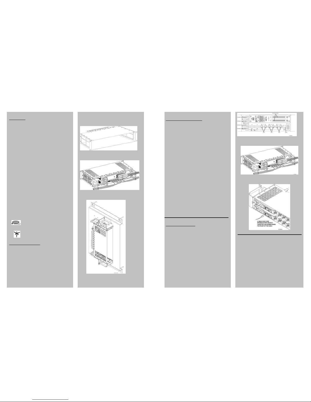
Figure 1. TE-206 (VLX2006) Shelf with 19-inch Brackets
Figure 2. TE-206 (VLX2006) Shelf with 23-inch Brackets
Figure 3. TE-206 (VLX2006) Wall Mounting Kit
Rear Interface Connections
The TE-206 (VLX2006) requires cabling any required electrical interfaces to the
back of the shelf. The rear interface panel provides termination points for DS3
(T3), DS1 (T1), FastE (ETHLAN), and management (ETH-R) services.
DS1
The TE-206 (VLX2006) shelf provides up to 14 DS1 interfaces at the rear of the
shelf via two 64-pin Champ connectors with shielded hoods and a #4-40 screw
to secure them to the shelf. The top connector is labeled “Out” and the lower
connector is labeled “In”. Refer to the user documentation for cable pin out
information.
DS3
DS3 interfaces are provided by six BNC connectors labeled 1 through 3 and “In”
or “Out”.
FastE
Four RJ-45 connectors located on the left side of the backplane interconnect
panel provide electrical FastE interfaces. If utilizing a protected FastE interface
at the rear of the shelf (protected by both cassettes), the corresponding SFP
port on each cassette may not be equipped with SFP modules. An unprotected
rear FastE port allows the use of one corresponding cassette port, but not both.
The left-most SFP port on each cassette corresponds to the top FastE
connector at the rear of the shelf.
Management
The TE-206 (VLX2006) has an RJ-45 connector for management purposes
located on the back of the shelf. It is redundantly routed to both cassettes and is
controlled by the active cassette. Using this Ethernet connection, both local and
remote nodes can be managed by TL-1 and HTTP (HyperText Transfer
Protocol). This interface is primarily intended for attaching Ethernet-based
devices, such as routers for the office LAN, to the system for management.
n Verify the selected cable is long enough to reach to the cable termination
location.
o Connect the appropriate cable to the shelf at the appropriate port until it seats
into place.
p For T1 cable connectors, use a screwdriver to carefully secure the connector
in place on one end using the screw retainer.
q Route the cables to the side of the shelf as shown in Figure 22 and secure to
the cable routing brackets using cable ties or lacing per local practices.
Quick Commissioning
The TE-206 (VLX2006) is a self-provisioning system, and on initial system
power-up, provisions all installed equipment and facilities. Verify the NE
inventory for the node using the Equipment Inventory menu option listed under
the General heading after login.
1. Connectivity
The front craft Ethernet port on each cassette has a default IP address so users
can configure the IP setting of the PC to match the default IP address subnet,
and gain access from either cassette immediately.
n Plug the User Port Communication Cable (or a crossover Ethernet cable)
into either RJ-45 user port. Plug the RJ-45 connector from the User Port
Communications cable into a PC or workstation with Internet Explorer (IE)
5.5 or higher installed. See Figure 23.
o Invoke IE. In the address field of IE, enter the IP address of the front
Ethernet port. The default address for the front Ethernet port is 169.254.1.1
with netmask 255.255.0.0.
p The PC must be enabled by the user to talk to the TE-206 (VLX2006) system
and must be running Windows 98, NT, 2000, XP, or ME. Set the PC IP
address to 169.254.1.2 with a default gateway of 169.254.1.1.
¨ Note: If using Windows XP, refer to the VLX2006 User’s Guide (P/N 800-
0026-43) for special instructions.
Figure 21. Rear Interface Facility Identification
Figure 22. Cable Routing and Strain Relief
Figure 23. Connecting User Interface
2. Login
n Open the Internet browser.
o Type IP address 169.254.1.1 in the browser address field.
p The TN-Xsight
®
GUI Login screen appears. Type the user name as root in
Username field.
q In the Password field, type the password as admin_1.
r Click OK.
¨ Note: The administrator should change the default password as soon as
possible. Refer to the VLX2006 User’s Guide (P/N 800-0026-43).
To start the Quick Install, go to the Administration tab and select Quick Install
under the configuration heading.
3. TID
n Click the TID link on the left of the window.
o Type a unique name for the node in this network.
p Click OK to return to the Quick Install menu screen.
Page 7
© Copyright 2008 Turin Networks
 Loading...