

Turin Networks TraverseEdge 50, TE-50, TE-50-SS, TE-50-IA, TE-50-EV User Manual

Turin Networks Inc.
TraverseEdge 50
System Documentation
User Guide
Software Release 4.5.x
Publication Date: September 2007
Document Number: 800-0012-TR30 Rev. B
FCC Compliance
This equipment has been tested and found to comply with the limits for a Class A digital device, pursuant to Part
15 of the FCC Rules. This equipment generates, uses, and can radiate radio frequency energy and, if not
installed and used in accordance with the installation instructions may cause harmful interference to radio
communications.
Canadian Compliance
This Class A digital apparatus meets all requirements of the Canadian Interference-Causing Equipment
Regulations. Cet appareil numérique de la classe A respects toutes les exigences du Règlement sur le matériel
brouilleur du Canada.
Japanese Compliance
This is a Class A product based on the standard of the Voluntary Control Council for Interference by
Information Technology Equipment (VCCI). If this equipment is used in a domestic environment, radio
disturbance may occur, in which case, the user may be required to take corrective actions.
International Declaration of Conformity
We, Turin Networks, Inc. declare under our sole responsibility that the Traverse platform (models: Traverse
2000, Traverse 1600, and Traverse 600) to which this declaration relates, is in conformity with the following
standards:
EMC Standards
EN55022 EN55024 CISPR-22
Safety Standards
EN60950 CSA 22.2 No. 60950, ASINZS 3260
IEC 60950 Third Edition. Compliant with all CB scheme member country deviations.
Following the provisions of the EMC Directive 89/336/EEC of the Council of the European Union.
Copyright © 2007 Turin Networks, Inc.
All rights reserved. This document contains proprietary and confidential information of Turin Networks, Inc.,
and may not be used, reproduced, or distributed except as authorized by Turin Networks. No part of this
publication may be reproduced in any form or by any means or used to make any derivative work (such as
translation, transformation or adaptation) without written permission from Turin Networks Inc.
Turin Networks Trademarks
Turin Networks, the Turin Networks logo, Traverse, TraverseEdge, TransAccess, TransNav, and Creating the
Broadband Edge are trademarks of Turin Networks, Inc. or its affiliates in the United States and other countries.
All other trademarks, service marks, product names, or brand names mentioned in this document are the
property of their respective owners.
Government Use
Use, duplication, or disclosure by the U.S. Government is subject to restrictions as set forth in FAR 12.212
(Commercial Computer Software-Restricted Rights) and DFAR 227.7202 (Rights in Technical Data and
Computer Software), as applicable.

Turin Networks, Inc. Preface
Preface
TABLE OF CONTENTS
1 PREFACE............................................................................................................................. 3
1.1 AUDIENCE ..................................................................................................................... 3
1.2 IF YOU NEED HELP....................................................................................................... 3
1.3 CONVENTIONS.............................................................................................................. 3
Page i

Turin Networks, Inc. Preface
Page ii

Turin Networks, Inc. Preface
1 PREFACE
This document is a field guide for the hardware installation and initial configuration of the Turin
TraverseEdge 50 (TE-50) Product.
The manual is divided into chapters for easy reference. The index outlining the chapters is located in
the document titled “Index”. Each chapter also contains a table of contents for that particular chapter.
This guide describes how to unpack and install the main hardware chassis and the installation and
removal of IMs. The installer is introduced to the operation of the front panel and diagnostic features
of the TE-50 products and the interpretation of the front panel displays. TransNav EdgeView is
introduced for basic port configuration and connection.
1.1 AUDIENCE
This document is intended for use by Communications Technical staff that will physically install and
maintain the TE-50 in a private or public voice and/or data service network.
Installing technicians should be familiar with the communications network protocols, nature and
requirements of services and systems connected to the TE-50.
1.2 IF YOU NEED HELP
If you need assistance while working with TE-50 products, contact the Turin Networks Technical
Assistance Center (TAC):
• Inside the U.S.: 1-866-TURINET (866-887-4638).
• Outside the U.S.: 707-665-4400.
• Online: www.turinnetworks.com/technical.htm.
TAC is available 6:00AM to 6:00PM Pacific Time, Monday through Friday (business hours). When the
TAC is closed, emergency service only is available on a callback basis. E-mail support (24-hour
response) is also available through at: support@turinnetworks.com.
1.3 CONVENTIONS
This publication uses the following conventions:
Note: contains information that may be useful to the reader.
Caution: specifies important information that will assist with a successful implementation of
the product described.
Warning: contains information that may impact on issues of personal safety.
Page 3

Turin Networks, Inc. Preface
Page 4

TE-50 User Guide
Contents

Turin Networks, Inc. TE-50 User Guide Table of Contents
TABLE OF CONTENTS
SECTION 1: TE-50 PRODUCT OVERVIEW
Chapter 1-1: Introduction to Turin TraverseEdge 50 Products
Chapter 1-2: TE-50 Chassis and Operating Environment
Chapter 1-3: TE-50 Integrated Access (IA) Product Specifics
Chapter 1-4: SDH/SONET (SS) Product Specifics
Chapter 1-5: SDH-AU4 Terminal Mode Point-to-Point Configuration Example
Chapter 1-6: SONET OC-3 Ring UPSR Configuration Example
Chapter 1-7: SDH-AU3 Linear 1+1 Configuration Example
Chapter 1-8: SONET OC-12 Ring UPSR Configuration Example
SECTION 2: TE-50 INTERFACE MODULES
Chapter 2-1: Interface Module Overview
Chapter 2-2: Dual E1 IM
Chapter 2-3: MPS IM
Chapter 2-4: FXS IM
Chapter 2-5: E&M IM
Chapter 2-6: STM-1 (OC-3) IM
Chapter 2-7: E3 /DS-3 IM
Chapter 2-8: Dual T1 IM
Chapter 2-9: Dual Ethernet IM
Chapter 2-10: Octal E1 IM
Chapter 2-11: Octal T1 IM
Chapter 2-12: Dual CoDirectional IM
Chapter 2-13: E3 – DS3 (M13) Multiplexer IM
Chapter 2-14: STM-1 & OC-3 Linear (1+1) IM
Chapter 2-15: Dual FXO IM
Chapter 2-16: STM-1 Electrical (STS-3) IM.doc
Chapter 2-17: TeleProtection Fiber IM
SECTION 3: TRANSNAV EDGEVIEW
Chapter 3-1: TransNav EdgeView Setup and Configuration
Chapter 3-2: Node and Network Clocks
Chapter 3-3: Digital Access Cross Connect Switch (DACS)
Chapter 3-4: SDH/SONET – Tributary Connections
Chapter 3-5: Remote Management of TE-50 Products
Chapter 3-6: Ethernet – Tributary Connections
Chapter 3-7: E3-DS3 Mux – Tributary Connections
Page i

Turin Networks, Inc. TE-50 User Guide Table of Contents
SECTION 4: APPLICATION NOTES
Chapter 4-1: Voice Networking Applications
Chapter 4-2: MPS DCE/DTE Clocking
SECTION 5: APPENDICES
Appendix A: Turin Cables
Appendix B: Software Updates with TE-50Upgrade
Appendix C: Types of Signaling for Voice Networks
Page ii

Turin Networks, Inc. TE-50 User Guide Table of Contents
Page iii

Section 1:
TE-50 Product Overview

Page : ii

Turin Networks, Inc. Ch1-1 Introduction to Turin TraverseEdge 50 Products.doc
Chapter 1-1:
Introduction to Turin TraverseEdge 50
Products
Page i

Turin Networks, Inc. Ch1-1 Introduction to Turin TraverseEdge 50 Products.doc
Page ii

Turin Networks, Inc. Ch1-1 Introduction to Turin TraverseEdge 50 Products.doc
CHAPTER 1-1: TABLE OF CONTENTS
1 INTRODUCTION .................................................................................................................. 1
2 TURIN TE-50 PRODUCTS ................................................................................................... 2
2.1 TE-50-IA.......................................................................................................................... 2
2.2 TE-50-SS ........................................................................................................................ 2
2.3 TE-50-EV ........................................................................................................................ 3
2.4 INTERFACE MODULES ................................................................................................. 3
2.5 TRANSNAV EDGEVIEW ................................................................................................ 3
TABLE OF FIGURES
FIGURE 1 - TE-50-IA ........................................................................................................................................ 2
FIGURE 2 - TE-50-SS....................................................................................................................................... 3
Page i

Turin Networks, Inc. Ch1-1 Introduction to Turin TraverseEdge 50 Products.doc
Page ii

Turin Networks, Inc. Ch 1-1 Introduction to Turin Products
1 INTRODUCTION
All Turin products are designed to assist telecommunications network operators to provide a large
number of voice and data services from a confined space and in a highly efficient manner.
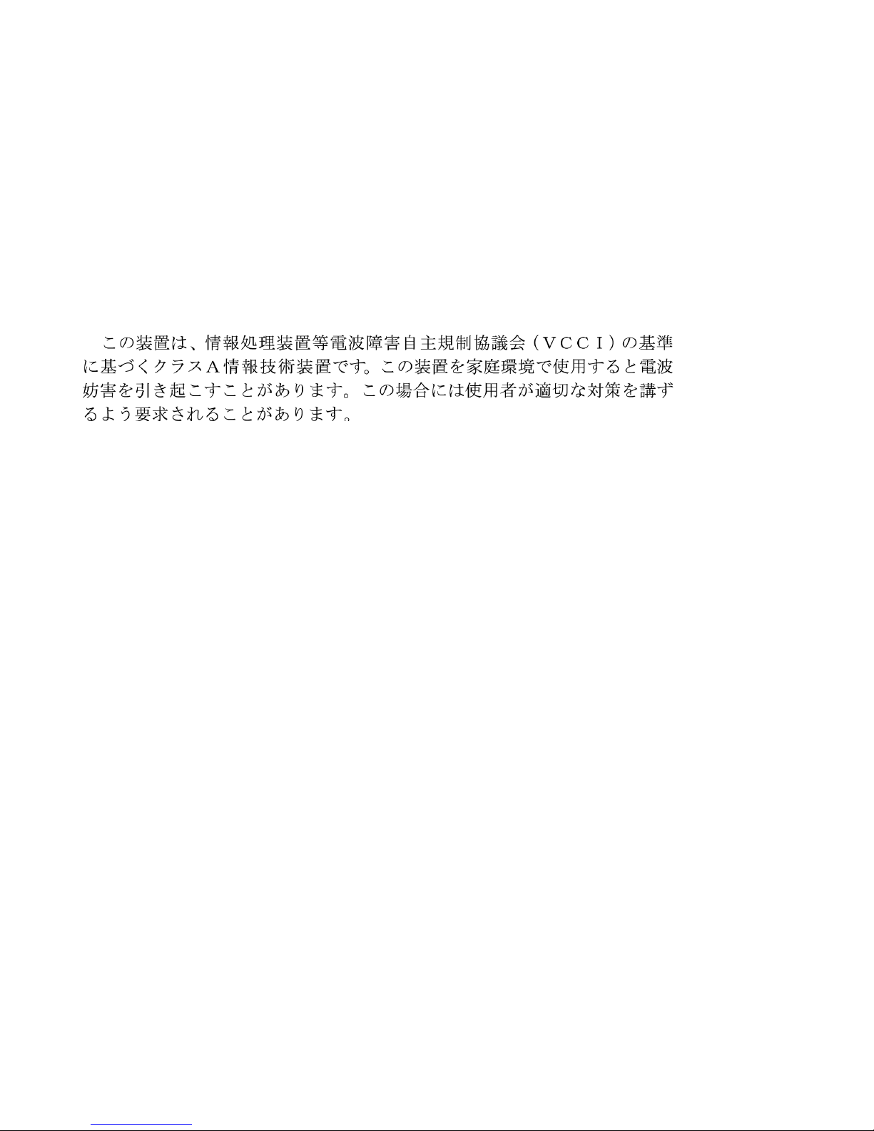
There are three product ranges of Turin TE-50 family nodes available. T
TE-50-EV, which are housed in a single Rack Unit (1RU = 1.75 inches high) rack mount device with
16 available slots for Interface Modules (IMs). (Refer to Figure 1) These slots are numbered 01-16.
All TE-50 nodes allow for a variety of voice and data services using insertable IMs that can be added
and remove
the actual services required when they are required.
The configuration and management of all nodes and IMs is performed in TransNav EdgeView, a
Windows® based Element Management Syste
An introduction to each product follows. For more details, example applications and operating
instruction
Manual.
d as required. This allows service providers to optimize their networks by installing only
m GUI application.
s refer to the specific online help and/or chapters of the Turin Installation and Configuration
he TE-50-SS, TE-50-IA, and
Page 1

Turin Networks, Inc. Ch 1-1 Introduction to Turin Products
2 TURIN TE-50 PRODUCTS
2.1 TE-50-IA
The TE-50-IA is a modern channel bank multiplexer solution, provided in a small single Rack Unit
device that provides up to 30 or 24 channels of data or voice connectivity for an E1 or T1 trunk circuit
connection respectively. Just as easily the TE-50-IA can be used to groom up to 32 x fractional E1
and T1 interfaces in the internal 1024 x 1024 x DS0 Digital Access Cross Connect Switch.
Figure 1 - TE-50-IA
The use of Interface Modules minimizes capital expenditure and simplifies service connectivity.
2.2 TE-50-SS
The TE-50-SS supports both Path based protection methodologies (SNCP or UPSR) and circuit
switched protection methodologies (MSP or Line 1+1).
The TE-50-SS integrates SDH/SONET transmission and multiplexing with Optical Multiplexing, Crossconnect, and Integrated Access functionality. This saves the user investing in separate traditional
access and switching equipment.
The system is standards based and interworks with traditional PDH and SDH/SONET networks
allowing customers to evolve their networks with operational simplicity.
Page 2
Turin Networks, Inc. Ch 1-1 Introduction to Turin Products
Figure 2 - TE-50-SS
2.3 TE-50-EV
The TE-50-EV is a data multiplexer that combines T1 and 10/100 Base T Ethernet transmission
across DS-3 trunks, supporting up to 8 10/100 Base T Ethernet IMs and 28 Dual T1 IMs. The
TE-50-EV can only be connected with another TE-50-EV.
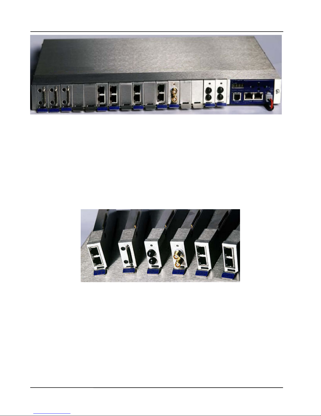
2.4 INTERFACE MODULES
The Interface Modules (IMs) come in a number of variants, allowing connection to a variety of voice
and data services. Each IM’s I/O is presented on its front panel.
Figure 3 – Interface Module
More information on the IMs is available with their individual configuration and operation in Chapter 4
of this section.
2.5 TRANSNAV EDGEVIEW
TransNav EdgeView is a Windows® based Graphical User's Interface EMS application that allows a
user to manage and configure TE-50 nodes and Interface Modules via software.
For more information on TransNav EdgeView, refer to Section 3 of this TE-50 manual.
Page 3

Turin Networks, Inc. Ch 1-1 Introduction to Turin Products
Page 4

Chapter 1-2: TE-50 Chassis and
Operating Environment


Turin Networks, Inc. Ch 1-2: TE-50 Chassis and Operating Environment
CHAPTER 1-2: TABLE OF CONTENTS
1. INSTALLATION ......................................................................................................................... 1
1.1. SITE REQUIREMENTS....................................................................................................... 1
1.1.1. DC POWER ................................................................................................................ 1
1.1.2. AC POWER ................................................................................................................ 1
1.1.3. GROUND CONNECTOR............................................................................................ 1
1.2. SITE ENVIRONMENT ......................................................................................................... 2
1.3. PREVENTATIVE SITE CONFIGURATION: MAINTAINING NORMAL OPERATION ......... 2
1.3.1. GENERAL PRECAUTIONS........................................................................................ 3
1.3.2. POWER CONSIDERATIONS ..................................................................................... 3
1.3.3. INSTALLATION PRECAUTIONS ............................................................................... 3
2. SAFETY RECOMMENDATIONS............................................................................................... 4
2.1. SAFETY WITH ELECTRICITY ............................................................................................ 5
2.2. PREVENTING ELECTROSTATIC DISCHARGE DAMAGE ................................................ 6
2.3. SAFETY WITH LASER RADIATION ................................................................................... 6
3. CHASSIS DIMENSIONS............................................................................................................ 7
3.1. TE-50 CHASSIS .................................................................................................................. 7
4. MOUNTING................................................................................................................................8
4.1. RACK MOUNT..................................................................................................................... 8
4.2. BENCHTOP......................................................................................................................... 8
5. INSTALLING INTERFACE MODULES (IM'S)........................................................................... 9
6. PRODUCT LABELLING .......................................................................................................... 10
6.1. ELECTROMAGNETIC COMPATIBILITY (EMC) ............................................................... 10
6.2. SAFETY............................................................................................................................. 10
6.3. IMMUNITY ......................................................................................................................... 10
Page i

Turin Networks, Inc. Ch 1-2: TE-50 Chassis and Operating Environment
TABLE OF FIGURES
FIGURE 1 – TE-50 DIMENSIONS .................................................................................................................... 7
FIGURE 2 - INSTALLING AN
IM....................................................................................................................... 9
LIST OF TABLES
TABLE 1 – ENVIRONMENTAL SITE REQUIREMENTS.................................................................................. 2
TABLE 2 – TE-50 CHASSIS SPECIFICATIONS .............................................................................................. 7
TABLE 3 – IM SLOT MAXIMUM BANDWIDTH ................................................................................................ 9
Page ii

Turin Networks, Inc. Ch 1-2: TE-50 Chassis and Operating Environment
1 INSTALLATION
1.1 SITE REQUIREMENTS
To ensure normal operation and avoid unnecessary maintenance, plan your site configuration and
prepare your site before installation.
1.1.1 DC POWER
The DC-input power supply operates at -48 volts direct current (VDC) input voltage and supplies
-48VDC power to the channel bank's internal components through the TE-50 midplane.
Note: Each Turin DC-input power supply uses a common 4 pole connector that has an
electrical current rating of 10A. Although the TE-50 has a current draw of only 3A, use a
minimum of 16 AWG (1.25mm 2) wire for the input to each DC-input power supply. This allows
use of a common DC power cable for all Turin DC powered products. The power input must be
protected by a 10A circuit breaker or fuse that is in compliance with your local electricity
regulations.
1.1.2 AC POWER
The TE-50 chassis can be optionally ordered with an external AC-input power supply. The external
AC supply has an input rated at 100 to 240 VAC at 1.5A and 50 to 60Hz.
1.1.3 GROUND CONNECTOR
All TE-50s must be connected to an electrical ground. The equipment grounding should be in
accordance with local and national electrical codes. Use a minimum of 16 AWG (1.25 mm
the ground connection.
All communications equipment should be connected to a common ground. This will result in
improved data communications. Rack mounted systems may use the equipment rack as the
ground path.
2
) wire for
1.1.3.1 TE-50 GROUND CONNECTOR
The Turin TE-50 series must be connected to electrical ground using the ground stud on the face of
the front panel. This is a safety feature.
Page 1

Turin Networks, Inc. Ch 1-2: TE-50 Chassis and Operating Environment
1.2 SITE ENVIRONMENT
Table 1 lists the operating and non-operating environmental site requirements. The following ranges
are those within which the Turin TE-50 series will continue to operate; however, a measurement that
is approaching the minimum or maximum of a range indicates a potential problem. You can maintain
normal operation by anticipating and correcting environmental anomalies before they approach a
maximum operating range. The Turin TE-50 products are designed for highly reliable operation and
are cooled by a fan mounted inside the case. The fan openings at the rear of the chassis should be
maintained clear of obstruction to allow airflow. Optimal airflow to the fan can be maintained if blank
panels are installed in all unused Interface Module (IM) slots.
Temperature, ambient
operating
Temperature, ambient
non-operating and storage
Humidity, ambient (noncondensing) operating
Humidity, ambient (noncondensing) nonoperating,
and storage
Altitude, operating, and
nonoperating
Vibration, operating 5 to 200 Hz
Vibration, nonoperating
DC power
(nominal 48 VDC)
Min Max
0 degrees Celsius
(32 degrees Fahrenheit)
-20 degrees Celsius
(-4 degrees Fahrenheit)
10%
5%
Sea level
0.5 g (1 oct./min.)
5 to 200 Hz,
1 g (1 oct./min.)
40 volts DC
50 degrees Celsius
(122 degrees Fahrenheit)
65 degrees Celsius
(149 degrees Fahrenheit)
90%
95%
10,000 feet (3,050 meters)
-
200 to 500 Hz
2 g (1oct./min.)
60 Volts DC
Table 1 – Environmental Site Requirements
1.3 PREVENTATIVE SITE CONFIGURATION: MAINTAINING NORMAL
OPERATION
Planning a proper location for the Turin chassis and designing the layout of your equipment rack or
wiring closet is essential for successful system operation. Equipment placed too close together or
inadequately ventilated can cause system over-temperature conditions.
Following are precautions that can help avoid problems during installation and ongoing operation.
Page 2

Turin Networks, Inc. Ch 1-2: TE-50 Chassis and Operating Environment
1.3.1 GENERAL PRECAUTIONS
Follow these general precautions when planning your equipment locations and connections:
• Turin recommends keeping equipment off the floor and out of any area that tends to collect dust,
excessive condensation
• Follow ESD prevention procedures to avoid damage to equipment. Damage from static discharge
can cause
• Ensure that the IMs and any IM slot blank plates are in place and secure. The blank plates secure
the electromagnetic prot
immediate or intermittent equipment failure.
, or water.
ection of the TE-50 unit and optimize the cooling air flow.
1.3.2 POWER CONSIDERATIONS
When planning power connections to the Turin TE-50 products, check the power at your site before
installation and periodically after the installation, to ensure that you are receiving clean power. Install a
power conditioner if necessary.
1.3.3 INSTALLATION PRECAUTIONS
The following guidelines will help to ensure your safety and protect the equipment. This list does not
cover all potentially hazardous situations, so be alert.
• The installation of your Turin products should be in compliance with national and local electrical
codes.
• Always turn all power supplies OFF (0) and unplug all power cables before opening the chassis.
• Always unplug the power cable before installing or removing a chassis.
• Keep the chassis area clear and dust free during and after installation.
• Keep tools and chassis components away from walk areas.
• Do not wear loose clothing, jewellery (including r
caught in the chassis.
ings and chains), or other items that could get
Page 3

Turin Networks, Inc. Ch 1-2: TE-50 Chassis and Operating Environment
2 SAFETY RECOMMENDATIONS
The following guidelines will help to ensure your safety and protect the equipment. This list does not
cover all potentially hazardous situations, so be alert.
• The installation of your Turin TE-50 should be in compliance with national and local electrical
codes.
• Always turn all power supplies OFF (0) and unplug all power cables before opening the chassis.
• Always unplug the power cable before installing or removing a chassis.
• Keep the chassis area clear and dust free during and after installation.
• Keep tools and chassis components away from walk areas.
• Do not wear loose clothing, jewellery (including rings and chains), or other items that could get
caught in the chassis.
• The Turin TE-50 series ships with a 2-wire electrical plug, which will fit into the TE-50 DC power
inlet. The other end of the supplied cable should be connected to a 48VDC supply. Use a
minimum of 16 AWG (1.25 mm
2
) wire for the input to each DC-input power supply.
• The Turin TE-50 series operates safely when it is used in accordance with its marked electrical
ratings and product usage instructions.
The Turin TE-50 series must be connected to an electrical ground using the ground connector
on the face of the front panel on the TE-50. This is a safety feature. The equipment grounding
should be in accordance with local and national electrical codes. Use a minimum of 16 AWG
(1.25 mm
2
) wire for the ground connection.
Warning: Only trained and qualified personnel should be allowed to install or replace this
equipment.
Note: For Australia and New Zealand, equipment is to be installed and maintained by service
personnel only as defined by AS/NZS 6950-2000 clause 1.2.13.5 Service Personnel.
Warning: Ultimate disposal of this product should be handled according to all national laws
and regulations.
Warning: Dispose of used components that contain batteries according to the manufacturer's
instructions.
Page 4

Turin Networks, Inc. Ch 1-2: TE-50 Chassis and Operating Environment
Caution: You must power down the system before removing or replacing motherboard, power
supply or midplane. Follow these basic guidelines when working with any electrical equipment:
2.1 SAFETY WITH ELECTRICITY
The Interface Modules are designed to be removed and replaced while the system is operating
without presenting an electrical hazard or damage to the system.
Before beginning any procedures requiring access to the chassis interior, locate the
emergency power-off switch for the room in which you are working.
Disconnect all power and external cables before installing or removing a chassis.
Do not work alone if potentially hazardous conditions exist.
Never assume that power has been disconnected from a circuit; always check.
Do not perform any action that creates a potential hazard to people or makes the equipment
unsafe.
Never install equipment that appears damaged.
Carefully examine your work area for possible hazards such as moist floors, ungrounded
power extension cables, and missing safety grounds.
Warning: Before working on a chassis or working near power supplies, unplug the power cord
on AC units; disconnect the power at the circuit breaker on DC units.
In addition, use the guidelines that follow when working with any equipment that is
disconnected from a power source, but still connected to telephone wiring or other network
cabling:
Never install telephone wiring during a lightning storm.
Never install telephone jacks in wet locations unless the jack is specifically designed for wet
locations.
Never touch uninsulated telephone wires or terminals unless the telephone line has been
disconnected at the network interface.
Use caution when installing or modifying telephone lines.
Warning: Before opening the chassis, disconnect the telephone-network cables to avoid
contact with telephone-network voltages.
Warning: The telecommunications lines must be disconnected 1) before unplugging the main
power connector and/or 2) while the housing is open.
Warning: Do not work on the system or connect or disconnect cables during periods of
lightning activity.
Page 5

Turin Networks, Inc. Ch 1-2: TE-50 Chassis and Operating Environment
2.2 PREVENTING ELECTROSTATIC DISCHARGE DAMAGE
Electrostatic discharge (ESD) damage, which occurs when electronic cards or components are
improperly handled, can result in complete or intermittent system failures. Each IM consists of a
printed circuit board that is fixed in a metal carrier. Electromagnetic interference (EMI) shielding,
connectors, and a handle are integral components of the carrier. Although the carrier helps protect the
boards, use an antistatic strap whenever handling. Handle the IMs by the case only; never touch the
boards or connector pins.
Following are guidelines for preventing ESD damage:
• Always use an ESD wrist strap or ankle strap and ensure that it makes good skin contact.
• When handling a removed IM or motherboard, make sure the equipment end of your ESD strap is
attached to an unfinished chassis surface of the TE-50; do not touch the printed circuit board, and
avoid contact between the printed circuit board and your clothing.
• Always place IM or motherboard component side up on an antistatic surface or in a static shielding
bag. If you are returning the item to the factory, immediately place it in a static shielding bag.
Caution: For safety, periodically check the resistance value of the antistatic strap. The
measurement should be between 1 and 10 Megohm (Mohm).
2.3 SAFETY WITH LASER RADIATION
If a fiber optic IM is installed in the TE-50, users must take suitable precautions to protect against
damage to eyes from Class 1 laser radiation.
The fiber optic IMs transmit invisible laser radiation. When not in use or connected to fiber optic
cables, the fiber optic IM connectors must have the dust caps fitted.
Warning: The fiber optic IM transmits invisible laser radiation.
Do not stare into beam or view directly with optical instruments.
This is a Class 1 laser product, operating at 1310nm or 1550nm, 0.5mW maximum.
Page 6
 Loading...