

Turin Networks MASTER series Quick Start Manual
MASTERseries
QUICK START GUIDE
Part Number: 002-0273-2010
Release: 7.0
October 2008

Copyright© 2008 Turin Networks. All rights reserved.
The information presented in this manual is subject to change without notice and does not represent a commitment on the
part of Turin Networks. The hardware and software described herein are furnished under a license or non-disclosure
agreement. The hardware, software, and manual may be used or copied only in accordance with the terms of this agreement.
It is against the law to reproduce, transmit, transcribe, store in a retrieval system, or translate into any medium - electronic,
mechanical, magnetic, optical, chemical, manual, or otherwise - any part of this manual or software supplied with
MASTERseries for any purpose other than the purchaser’s personal use without the express written permission of Turin
Networks.
The Turin Networks Logo is a registered trademark of Turin Networks. FLEXengine, FLEXmaster, MASTERseries and
OMC Companion are trademarks of Turin Networks. All other brand or product names are trademarks or registration
trademarks of their respective companies or organizations.
Corporate Contact Information:
Turin Networks, Inc.
1415 North McDowell Blvd.
Petaluma, CA 94954
Phone: +1-707-665-4400
Fax: +1-707-793-4935
www.TurinNetworks.com
Turin Technical Assistance Center:
E-mail: tech-support@TurinNetworks.com
Phone (US): 1-800-887-4638
Phone (International/Direct): 1-707-665-4355

Safety Information
CAUTION! ALWAYS USE CAUTION WHEN INSTALLING TELEPHONE LINES. READ THE CAUTIONS
BELOW FOR DETAILS ON SAFETY GUIDELINES TO PREVENT INJURY.
z The installation of a MASTERseries unit is to be performed by qualified personnel only.
z Never touch uninsulated telephone wires and terminals unless the telephone line has been
disconnected at the Network Interface (NI) as voltage potentials as high as 300 VAC may be
present across the transmit and receive pairs.
z Only use No. 26 AWG or larger telecommunication line cord, to reduce the risk of fire.
z Never install telephone wiring during a lightning storm.
z Never install telephone jacks in wet locations unless the jack is specifically designed for wet
locations.
PREFACE
Preface
z Refer to the installation section of this manual for a safe and proper installation procedure. All
wiring external to this equipment should follow the current provision of the National Electrical
Code.

Preface
Electrostatic Discharge (ESD) Precautions
Electrostatic Discharge (ESD) Precautions
ESD can damage processors, circuit cards, and other electronic components. Always observe the
following precautions before installing a system component.
1. Do not remove a component from its protective packaging until ready to install it.
2. Wear a wrist grounding strap and attach it to a metal part of the system unit before handling
components. If a wrist strap is not available, maintain contact with the system unit throughout
any procedure requiring ESD protection.
WARNING! INTEGRATED CIRCUITS (ICS) ARE EXTREMELY SUSCEPTIBLE TO ELECTROSTATIC
DISCHARGE. UNLESS YOU ARE A QUALIFIED SERVICE TECHNICIAN WHO USES TOOLS AND
TECHNIQUES THAT CONFORM TO ACCEPTED INDUSTRY PRACTICES, DO NOT HANDLE ICS.
The ESD warning label appears on packages and storage bags that contain
static-sensitive products and components.
4 MASTERseries - Release 7.0

QUICK START GUIDE
MASTERseries Quick Start Guide
In this Guide
Unpacking and Inspection
Installation Environment
2-Slot Chassis Installation
8-Slot Chassis Installation
Local Management - Logging in to the
FLEXmaster
Connectors
LEDs
NOTE: Multiple modules, master/slave functionality, and E1 functionality are not supported
in this release.

MASTERseries Quick Start Guide
Unpacking and Inspection
Unpacking and Inspection
WARNING! OBSERVE PRECAUTIONS FOR HANDLING ELECTROSTATIC DEVICES.
1. Inspect containers for damage during shipment. Report any damage to the freight carrier for
possible insurance claims.
2. Compare packing list with office records. Report any discrepancies to the office.
3. Open shipping containers, be careful not to damage contents.
4. Inspect contents and report any damage.
5. If equipment must be returned for any reason, carefully repack equipment in the original
shipping container with original packing materials if possible.
6. If equipment is to be installed later, replace equipment in original shipping container and store
in a safe place until ready to install.
Installation Environment
The environment in which you are installing the Adit 600 must meet the following conditions:
z Operating temperature range: -40° to 149° F (-40° to 65° C)
z Storage temperature range: -40° to 158° F (-40° to 70° C)
z Maximum operating altitude: 10,000 ft. (3,048 m)
z Minimum operating altitude: 197 ft. (60 m) below sea level
z Maximum non-operating altitude: 40,000 ft. (12,192 m)
z Relative humidity (non-condensing) range: 0 to 95%
6 MASTERseries - Release 7.0
MASTERseries Quick Start Guide
Application
Application
Power Supply
Slot 2
Power Supply
Slot 1
Module Slot 1
Module Slot 2
19"
1.75"
10.2"
2-Slot Chassis Installation
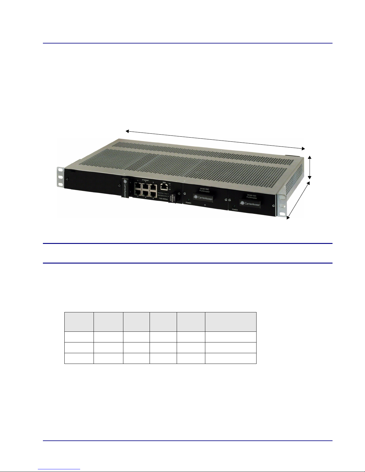
2-Slot Chassis Installation
The 2-slot chassis has two application module slots and two power supply slots for redundant power.
Dimensions:
z 1.75 in (H) x 19 in (W) x 10.2 in (D).
z Maximum depth of the shelf, including cables, is 12 inches
z Rack Mounting: 19 or 23 inch rack
NOTE: Blank faceplates must be installed on each empty slot to be in compliance with
product emission standards.
Supported Configurations
The following table indicates the configurations supported by the 2-slot chassis.
Double
Fan
For information about configurations supported by the 8-slot chassis, see 8-Slot Chassis Installation on
page 20.
Triple
Fan
9
9
9
FM16
TDM
11*
FM16
ATM
11*
FM16
PWE
11*
Total Number
of Modules
MASTERseries - Release 7.0 7
MASTERseries Quick Start Guide
19-inch Mounting
Bracket
23-inch Mounting
Bracket
black green
+ -
black
+ -
2-Slot Chassis Installation
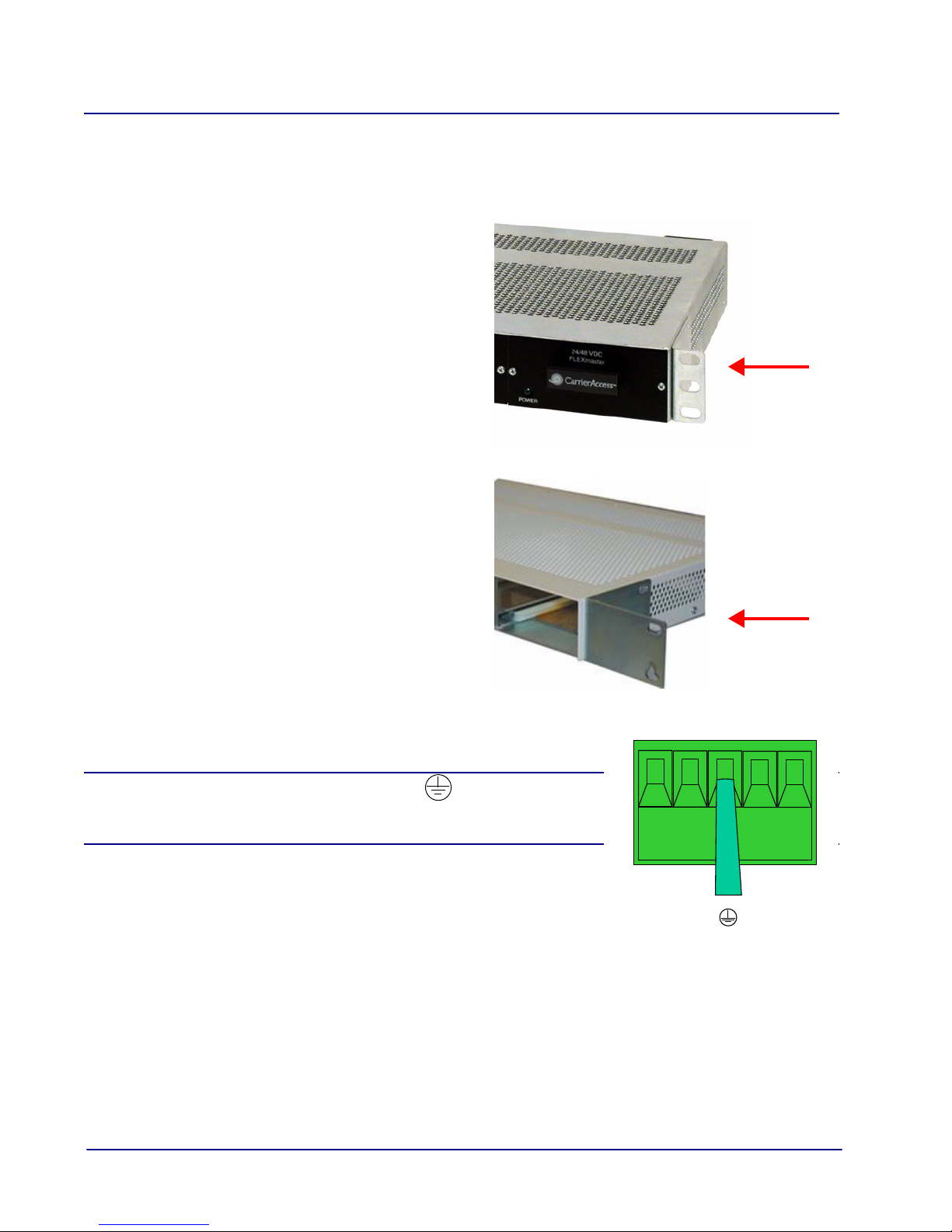
Rack Mount Installation
Mounting brackets for a 19-inch rack are installed on the chassis when shipped. If you want to install
the chassis in a 23-inch rack, you must purchase 23-inch mounting brackets from Turin Networks.
Installation of the 2-slot chassis is as follows:
1. To install the unit in a 19-inch rack, attach
the unit with the brackets to the rack using
the screws provided.
2. To install the unit in a 23-inch rack, remove
the 19-inch mounting brackets and replace
them with 23-inch mounting brackets
purchased from Turin Networks.
3. Ground the unit by attaching ground wire from the
terminal block to the frame ground.
WARNING! THE GROUND TERMINAL ON THE POWER
BLOCK MUST BE CONNECTED TO THE FRAME GROUND TO
PREVENT POSSIBLE DAMAGE TO THE EQUIPMENT.
8 MASTERseries - Release 7.0
MASTERseries Quick Start Guide
2-Slot Chassis Installation
Power Supply Installation and Cabling
DANGER! POSSIBLE SHOCK HAZARD EXISTS - PLEASE FOLLOW INSTRUCTIONS
CAREFULLY. ENSURE THAT NO POWER IS PRESENT ON POWER LEADS AND THAT
THE CHASSIS POWER SWITCH IS OFF WHEN PERFORMING THE PROCEDURES IN
THIS SECTION.
This section describes the power supplies used in the 2-slot chassis and provides instructions for
installing and setting up cabling for the power supplies.
+24/-48 VDC Power Supply
FLEXmaster modules are powered by +24/-48 VDC power supplies. The power supplies are
redundant and load sharing.
DC Configuration
+24/-48VDC (24 – 65VDC input) 30W dual 3.15A
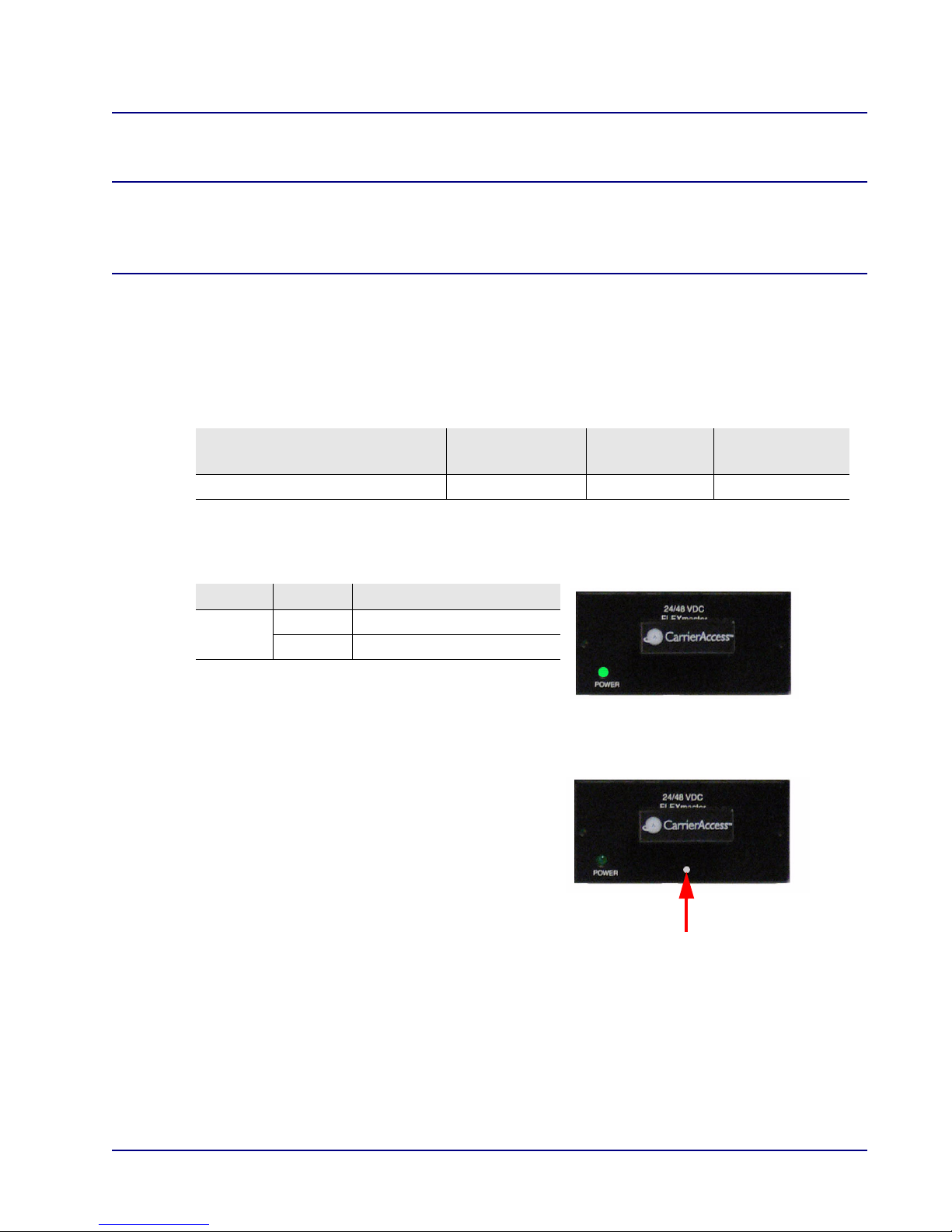
The LED states of the power supply are as follows
Power Supply
Wattage
:
Input Power
Feed(s)
Fuse
LED State Description
Power Off DC input missing or failure
Green DC input present
NOTE: MASTERseries Release 6.0 introduced a
new 24/-48 VDC power supply that is identified
by a small white dot on the faceplate.
MASTERseries - Release 7.0 9
MASTERseries Quick Start Guide
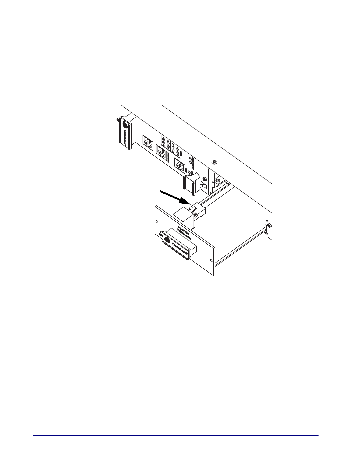
Fan Power Connector
2-Slot Chassis Installation
Power Supply Installation
To install the first power supply:
1. Remove the blank faceplate from power supply slot 2.
2. Slide the power supply halfway into the empty slot, and plug the fan’s power connector into
the power supply.
3. Slide the power supply the rest of the way into the slot. Press firmly to make full contact
with the connector at the back of the chassis.
4. Insert and tighten the screws on the front of the power supply.
5. For redundant systems, install a second power supply into power supply slot 1 following
the same procedure (except for connecting the fan).
10 MASTERseries - Release 7.0
MASTERseries Quick Start Guide
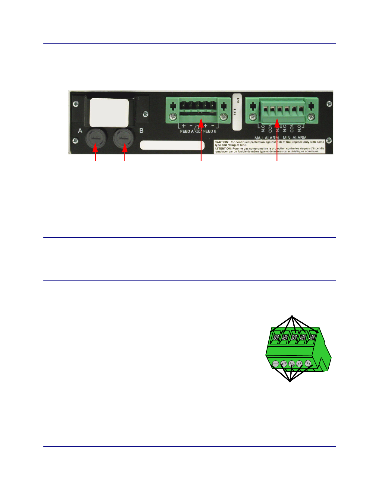
Power Entry Module Alarm Terminal Block
DC Line Input Fuses
(A and B feeds)
Connect 16-18
Wire Securing Screws
Gauge Wire Here
2-Slot Chassis Installation
Power Lead Connection
The +24/-48 VDC power entry module provides DC power protection and isolation when the leads
are properly attached.
Each input has its own return. The labels of the power entries vary based on what version of the
chassis you have:
z FEED A (IN A/RTN A) operates power supply A
z FEED B (IN B/RTN B) operates power supply B
DANGER! POSSIBLE SHOCK HAZARD EXISTS - PLEASE FOLLOW INSTRUCTIONS
CAREFULLY.
ENSURE THAT NO POWER IS PRESENT ON THE POWER LEADS TO BE CONNECTED
AND THAT THE CHASSIS POWER SWITCH IS OFF.
To connect the power leads:
1. Remove the power terminal block for easier lead attachment by
prying off the block with a screwdriver.
2. Strip the two wires from the power source so that approximately
5/16 inch of bare wire is exposed. 16 or 18 AWG insulated
copper wire is recommended for power connections.
3. Attach leads to the appropriate terminals using the screws on the
block to secure them. The illustrations on the following page
show the positioning of the leads.
4. Be sure to attach the ground wire as described in Rack Mount
Installation on page 8.
5. Ensure that no bare wire shows after the wires are installed.
6. IMPORTANT: Do not connect power yet.
MASTERseries - Release 7.0 11
 Loading...