

Turf Tick Products UNIVERSAL AUTOSTACKER Original Instructions Manual

AUTOSTEER
Original instructions
MODEL:
UNIVERSAL AUTOSTACKER
(Digital sensors)
(2-steered Trailer Wheels)
THIS MANUAL IS APPLICABLE FOR SERIAL NR:
1021, 1023, 1024, 1025, 1026, 1027, 1028, 1029, 1030 and up
Turf Tick Products B.V.
Harmelerwaard 21, 3481 LC Harmelen, Netherlands
Tel +31 (0)30 666 13 48 Fax +31 (0)30 666 13 40
www.turftick.com - info@turftick.com

1
1. Introduction ................................................................................................... 2
2. Autoseer: one control unit ............................................................................ 3
Overview components ............................................................................................................. 3
3. Basic operation of system: ............................................................................ 5
4. The mechanical parts ...................................................................................... 6
Mounting “Autosteer” mechanical parts ............................................................................. 8
4. Hydraulics: steering system tractor wheels .............................................. 10
5. Electronic scheme ........................................................................................ 12
PCB layout ............................................................................................................................ 13
Active area sensors ............................................................................................................... 13
6. Installing of the system ............................................................................... 15
7. Adjusting the sensors of the autosteer ....................................................... 15
7.1 Adjusting procedure: right side wheel sensor tractor .................................................... 16
7.2 Adjusting procedure: shoe sensor ................................................................................... 17
7.3 Adjusting procedure: left side trailer .............................................................................. 19
7.4 Adjusting procedure: right side trailer ........................................................................... 19
8. Adjusting the pressure relief valves .......................................................... 20
8.1 Adjusting pressure relief valve O1: should be same as tractor ...................................... 20
8.2 Adjusting pressure relief valve O2: steering sensitivity.................................................. 21
9. Adjusting ‘Free play’ for swingarm on PCB ............................................ 22
10. Adjusting ‘Ratio’ for steering .................................................................... 23
11. Troubleshoot ................................................................................................ 25

2
1. Introduction
The Turftick Autosteer system is an optional system used for automatic steering of the tractor
while harvesting on the field. With the autosteer system it is possible to control the steering of
the tractor wheels so the tractor will follow the sod edge. It is also possible to adjust the
amount of strip being left over (while driving).
For a correct functioning of the autosteer system it has to be correctly set up to the tractor that
is being used. The Turftick Autosteer system will only work with a tractor using a hydro-static
steering system. (This means the front wheels are steered by a hydraulic cylinder).
This manual explains the working of the system, describes all the hardware and adjustments.
With this information it is possible to understand how the Autosteer works so it will be
possible to readjust when necessary (for instance when replacing a sensor).
REMARK
This manual is only applicable for the Universal Autostackers equipped with:
*digital sensors, utilizing 1control unit, steering tractor and trailer wheels.
*2 steered wheels (except SN: 1023 & 1025 which have 1 steered trailer wheel)
3
2. Autoseer: one control unit
The Universal Autostacker uses 1 control unit for Autosteer. This control unit differs from the
regular Turftick (with hand stacking) in terms of hardware (different sensors) and software.
The control unit interacts between Autosteer shoe, right front wheel, trailer wheels and the
main operating box. This Autosteer system has been used on the later Universal Autostackers
which have 2 steered trailer wheels (except SN: 1023 & 1025).
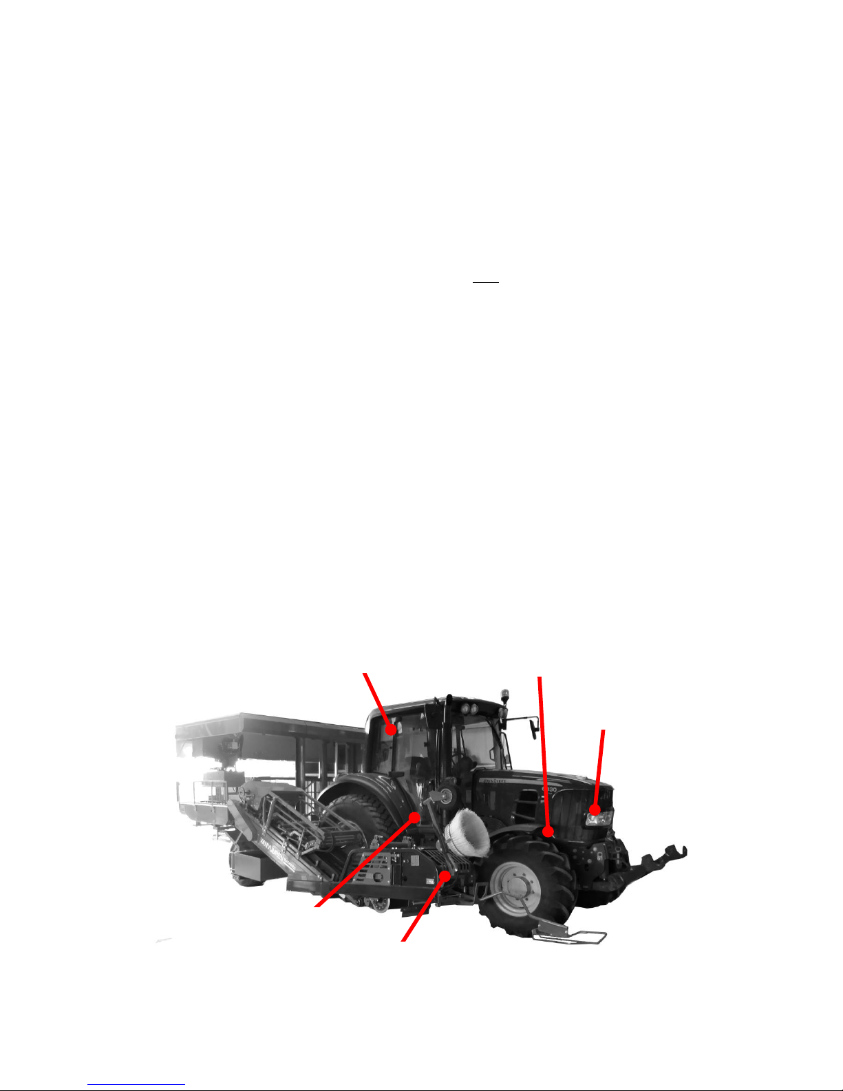
Overview components
*Shoe sensor: Placed on the Turftick
Measures angle position of shoe only while Autosteer is switched ‘ON’
(while harvesting sods on the field).
*Wheel sensor: Placed on right tractor wheel
Measures angle position of right tractor wheel.
*Valves tractor: Placed under the Tractor cabin (usually on right side)
When Autosteer is switched ‘ON’, this steering valve will steer tractor
wheels based on Shoe sensor position. These valves are engaged only
while driving on the field when the machine has to follow the sod edge
(position of shoe sensor).
*Control box: Placed inside the tractor cabin
The user can switch on/off the Autosteer and adjust ‘Offset’ value. This
‘Offset’ value adjusts the sod strip left behind on the field.
*Fusebox: Placed under the bonnet of tractor
Power supply for Autosteer control unit.
Valves Tractor
Shoe sensor
Control box
Wheel sensor
(right side)
fusebox
4
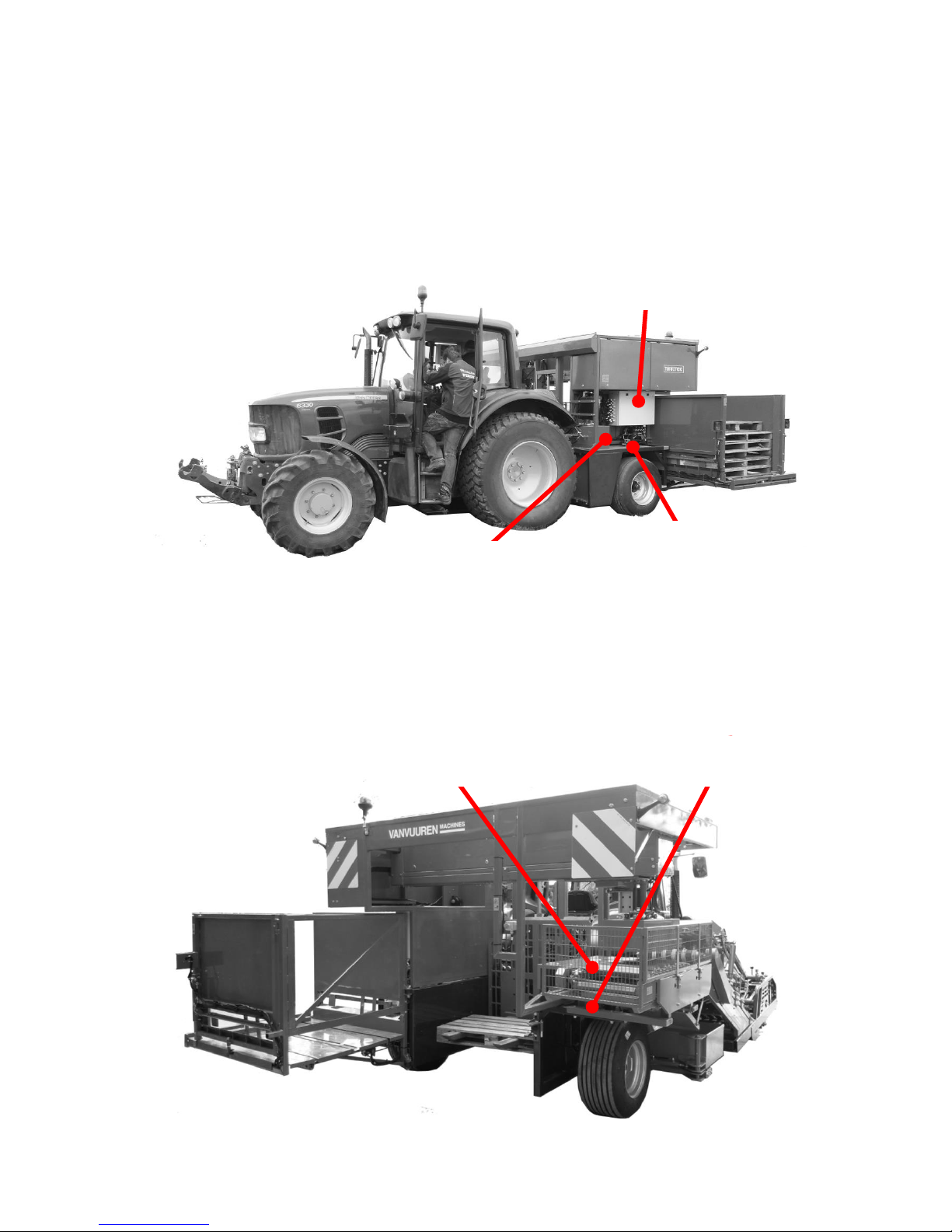
*Trailer sensor left: Placed on left tractor wheel
Measures angle position of left trailer wheel.
*Valves trailer left: Placed near left side trailer wheel
Steers only left trailer wheel.
*PCB: Placed in main control box, upper right side
*Trailer sensor right: Placed on right tractor wheel
Measures angle position of right trailer wheel.
*Valves trailer right: Placed near right side trailer wheel
Steers only right trailer wheel.
PCB
Valves Trailer left
Trailer left sensor
Trailer right
sensor
Valves Trailer right

5
3. Basic operation of system:
A shoe is mounted on front of the Turftick sod harvester which can move freely in all
directions. A spring pulls the shoe against the sod edge. The shoe will follow the sod edge.
If the tractor steers too much to the left, the spring will pull the shoe to the right side until it
follows the sod edge again. The movement which the shoe makes, is being read by the shoe
sensor. The control unit sends the necessary output to the steering cylinder of the front wheels
of the tractor. The (right) tractor wheel sensor is monitoring the amount of steering and will
stop the wheels from steering when it has reached its targeted angle. At the same time the rear
wheels are steering (at all times). Each trailer wheel has its own sensor and steering and
proportional valves.
WARNING
Always switch on PTO while driving. Without a running PTO the trailer wheels will
never steer!! Prevent hazardous situations which if not avoided could result in serious
injury or death.
The system usually needs to be set up only once. The procedures consist of:
*calibrating tractor wheel sensor: while tractor wheel is steering straight, adjust sensor
position until its status LED becomes blue.
*calibrating trailer wheels: adjust trailer wheel sensors until trailer wheels are steering straight
while tractor wheels are steering straight.
*calibrating shoe sensor: adjust shoe sensor position until sod strip (left behind on field) is +/1 cm while ‘Offset’ button is set on 5/6. Readjust if ‘Offset’ button has too little range.
*Adjust oil pressure for Autosteer valves steering tractor front wheels.
All sensors are set up once and never needs re-adjustments, unless it is being replaced with a
new sensor. If you replace a sensor, then it needs to be calibrated again (explained further in
this manual).
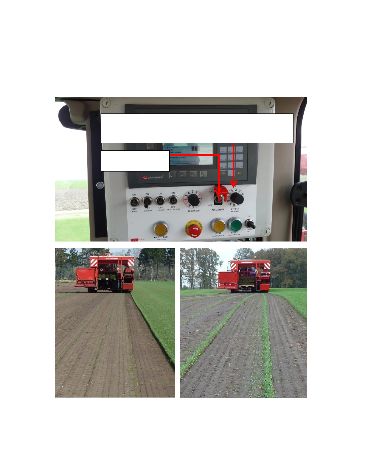
The control box has an ON/ OFF switch and an offset knob. This offset knob will regulate the
width of the sod edge which the sod harvester will leave behind while harvesting. If the range
of the offset is not properly set, adjustment of the shoe sensor can change the offset range.
6
Autosteer: OFFSET knob
It is possible to make fine adjustments to the Autosteer from the cabin. Turning the knob on
the Autosteer control box regulates the offset. As shown in the pictures below, it’s possible to
regulate the amount of sod strip left behind.
Little/ no sod strip left behind.
Big sod strip left behind.
OFFSET knob:
Used for leaving little up to big sod strip behind on field.
Position 5/6 is used as center position for sensor set-up Autosteer
Autosteer ON/OFF
switch
7
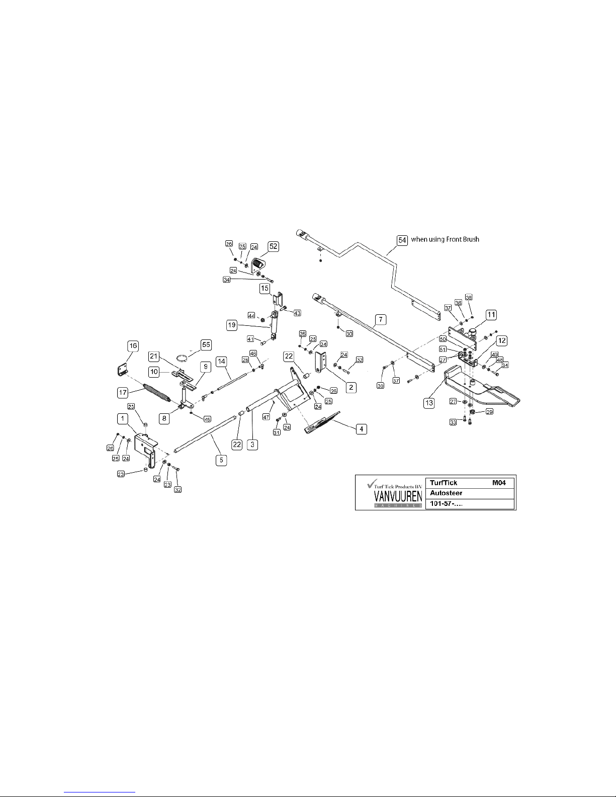
4. The mechanical parts
The mechanical part of the system consists of a construction mounted at the front of the Sod
machine. The most important part of this construction is the so called “Shoe” or “Foot” that
floats over the soil and is slightly pushed (by a spring) to the sod edge.
The shoe can be lifted by a little hydraulic cylinder. This hydraulic cylinder is not operated
electronic-hydraulic, but by the standard hydraulic-connection at the backside of each tractor.
Exploded view of the mechanical part of the Autosteer system.
 Loading...