


OPERAT OR’S
MANUAL
MODEL 1305BC
BRUSH CUTTER

COPYRIGHT 2009 by
Turf Teq, LLC
Honey Brook, PA 19344 U.S.A.
All rights reserved. No part of this publication may be reproduced, stored in a retrieval system, or
transmittedinanyformorbyanymeans,electronic,mechanical,photocopying,recording,orotherwise,
without prior written permission of Turf Teq, LLC.
DISCLAIMER: THE INFORMATION IN THIS MANUAL IS PROVIDED TO PROMOTE THE
SAFEUSE OF,ANDASSIST THEOPERATOR IN ACHIEVINGMAXIMUMPERFORMANCE
FROM THE MODEL 1305 BRUSH CUTTER AS DESCRIBED IN THIS MANUAL.

TABLE OF CONTENTS
INTRODUCTION 3......................................................................
OWNER ASSISTANCE 4................................................................
WARRANTY AND LIMITATION OF LIABILITY 6...........................................
SAFETY INFORMATION 10..............................................................
PERSONAL SAFETY 10..............................................................
MACHINE SAFETY 10................................................................
INTENDED USE 12.....................................................................
SURVEY THE AREA 12...............................................................
PERSONAL SAFETY DECALS 13........................................................
SAFETY DECAL INFORMATION 14......................................................
SERIAL NUMBER LOCATIONS 15.......................................................
TRACTOR SERIAL/MODEL NUMBER LOCATION 15....................................
ENGINE SERIAL NUMBER LOCATION 15..............................................
BRUSH CUTTER SERIAL NUMBER LOCATION 15......................................
CONTROL LOCATIONS - OVERVIEW 16.................................................
DAILY CHECKS TO PERFORM BEFORE STARTING THE ENGINE 17.......................
CHECK ENGINE OIL LEVEL 17.......................................................
CHECK FUEL LEVEL 17..............................................................
TRANSMISSION OIL LEVEL 17.......................................................
MAIN DRIVE BELT CONDITION 18....................................................
CHECK THAT ALL SHIELDS ARE IN PLACE AND HARDWARE IS TIGHT 18..............
CHECK TIRE PRESSURES 18........................................................
CHECK CLUTCH CABLE ADJUSTMENT 19............................................
CHECK BLADE SHARPNESS 19......................................................
CHECK BLADE NUT TORQUE 20.....................................................
GREASE MACHINE PIVOTS 20.......................................................
GENERAL CONTROLS 21...............................................................
PARK BRAKE (OPTIONAL EQUIPMENT) 21............................................
TRANSMISSION CONTROL LEVER (TOW VALVE) 22...................................
DIFFERENTIAL CONTROL 23.........................................................
BRUSH CUTTER SWING CONTROL 24................................................
PARKING THE MACHINE 27............................................................
ENGINE OPERATION 28................................................................
STARTING A COLD ENGINE 28.......................................................
STARTING A WARM ENGINE 29......................................................
STOPPING THE ENGINE 30..........................................................
1

OPERATING THE DIRECTIONAL SPEED CONTROLS 32..................................
PRELIMINARY STEPS TO MOVING THE MACHINE IN ANY
DIRECTION WITH ENGINE RUNNING 32...............................................
STOPPING MOVEMENT WITH ENGINE RUNNING 33...................................
VARIABLE SPEED CONTROL ADJUSTMENT 34........................................
ADJUSTING THE VARIABLE SPEED CONTROL 34.....................................
FORW ARD DIRECTION 35............................................................
REVERSE DIRECTION 35............................................................
OPERATING THE BRUSH CUTTER 36...................................................
STOPPING THE BRUSH CUTTER 36..................................................
SECURING THE BRUSH CUTTER FOR TRANSPORT 37..................................
BRUSH CUTTER SERVICE AND MAINTENANCE SCHEDULE 38...........................
SERVICE 39...........................................................................
ENGINE MAINTENANCE SEE ENGINE MANUFACTURES OWNER’S MANUAL...............
TRANSMISSION OIL LEVEL 39.........................................................
LUBRICATION 40......................................................................
LUBRICATE CONTROL CABLES 42...................................................
LUBRICATE PIVOT POINTS 42........................................................
MAIN DRIVE BELT 43..................................................................
CHECK MAIN DRIVE BELT CONDITION 43............................................
CHECK MAIN DRIVE BELT TENSION 44...............................................
REPLACING THE MAIN DRIVE BELT 45...............................................
INSTALLING THE MAIN DRIVE BELT 48...............................................
CLUTCH CABLE ADJUSTMENT 49...................................................
TRANSMISSION DRIVE BELT 52........................................................
CHECK AND ADJUST TRANSMISSION DRIVE BELT TENSION 52.......................
TRANSMISSION DRIVE BELT REPLACEMENT PROCEDURE 56.........................
REPLACING THE BLADE 63............................................................
BLADE INSTALLATION 65..............................................................
ATTACHING THE BRUSH CUTTER TO THE TRACTOR 66..................................
REMOVING THE BRUSH CUTTER FROM THE TRACTOR 81...............................
END OF SEASON STORAGE SERVICE 84................................................
SPECIFICATIONS 85...................................................................
TROUBLESHOOTING 86................................................................
2

INTRODUCTION
This manual is provided as a guide to help you safely operate the product and to achieve the maximum
performance from your Brush Cutter.
Before operating the Brush Cutter, thoroughly read the entire manual. It is important that you, the operator,
thoroughly understand how to operate the machine and adhere to all safety and operating procedures. Special
attention should be paid to all Safety Precautions which are detailed in this manual.
Instructions were written from the perspective that the operator is standing behind the machine grasping the
handlebars and facing the forward direction of travel.
Some pictures in this manual may show optional equipment installed or may not depict current production.
Please contact Turf Teq, LLC directly if, after reading the manual, you have questions about the safe operation
of this machine.
3

Thank you and congratulations on your purchase of a new Turf Teq Brush Cutter!
We are confident that your Brush Cutter will be one of the most gratifying pieces of equip-
ment you will ever own. As a result of your investment in the Brush Cutter, you will eliminate the need for manual back-breaking work and you will see an increase in productivity.
Your happiness is our goal, so please let us know of any questions or issues you may
have so that we may answer them or address them as quickly as possible. (Please have
your serial number available when you call us). We would also like to hear from you on
how much you enjoy your new Brush Cutter!
Turf Teq, LLC Toll Free (866) 503–TURF
4

Total Customer Satisfaction is our Goal
The Brush Cutter is designed to provide trouble-free operation. To ensure that you are
satisfied with your Brush Cutter, we offer the following Guarantee of Satisfaction:
• The Brush Cutter is GUARANTEED TO THE ORIGINAL PURCHASER FOR ONE
FULL YEAR against defects in materials and workmanship. If you feel that a part is defective, contact us and we replace the defective part and provide repair instructions as
required.
• The engine is guaranteed by the engine manufacturer:
Honda Engine: Two years in consumer use; two years in commercial use
• If your have questions or are not 100% satisfied with your Brush Cutter within the first
30 days of use, call us toll free at 1–866–503–TURF and we will work to answer your
questions and to resolve your concerns.
Please have the following information from your packing slip and from the Brush Cutter
available when contacting our customer service department:
Name of Purchaser
Tractor
Model
Serial Number
Date Purchased
Sales Order Number
Brush Cutter
Model
Serial Number
Date Purchased
Sales Order Number
5

Turf Teq, LLC
WARRANTY AND LIMITATION OF LIABILITY
(Customer Copy -- Page 1)
COVERAGE PROVIDED
Turf Teq, LLC, hereinafter called “Turf Teq” warrants to the original retail purchaser of each new Turf Teq
Product that Turf Teq will replace any part thereof found to be defective in materials or workmanship within
the time periods identified below.
DEFINITION
“Products” are machines, attachments, and Replacement Parts therefore supplied by Turf Teq.
WARRANTY
12 months from the date of first retail purchase.
Replacement Parts are warranted for 60 days or to the end of the Warranty Period, whichever is longer.
LIMITATIONS, INCLUDING DISCLAIMER OF IMPLIED WARRANTIES AND CONSEQUENTIAL
AGES
This warranty gives you specific legal rights and you may also have other rights that vary depending on
state or provincial laws.
Turf Teq does not authorize any person or Dealer to create for it any other obligation or liability in connection
with these Products. TO THE EXTENT ALLOWED BY LAW, ANY IMPLIED WARRANTY OF MERCHANT-
ABILITY OR FITNESS APPLICABLE TO THIS PRODUCT IS LIMITED TO THE STATED DURATION OF
THIS WRITTEN WARRANTY. TURF TEQ IS NOT LIABLE FOR LOSS OF THE USE OF THE PRODUCT,
LOSS OF TIME, INCONVENIENCE, COMMERCIAL LOSS OR CONSEQUENTIAL DAMAGES.
Some states and provinces do not allow limitations on how long an implied warranty will last or the exclusion
or limitation of incidental or consequential damages, so the above limitations or exclusions may not apply to
you.
The remedy of repair or replacement of a defective part during the warranty period herein specified shall be
the purchaser’s exclusive remedy.
RIGHT TO MAKE DESIGN
PERIOD
DAM-
CHANGES
Turf Teq reserves the right to make changes in the design and other changes in its Products at any time and
from time to time without notice and without incurring any obligation with respect to any product previously
ordered from it, sold or shipped by it.
6

Turf Teq, LLC
WARRANTY AND LIMITATION OF LIABILITY
(Customer Copy -- Page 2)
The warranty period will begin on the date of first retail sale.
The obligation of Turf Teq to purchase under this warranty is limited to the repair or replacement of
defective parts free of charge using genuine Turf Teq Replacement Parts. Repair or replacement in
accordance with this warranty shall constitute fulfillment of all liabilities of Turf Teq in respect to such
Products.
Your dealer shall review these warranty provisions with the purchaser prior to retail sale, secure his
acknowledgement of delivery of this warranty and record the date of first retail sale.
WHAT IS NOT COVERED BY THE WARRANTY?
This warranty shall NOT apply under the following conditions:
1. With respect to vendor warranty items such as engines, which shall be warranted by their manufacturer, or local representative
a. Honda Engines have a 2 YEAR WARRANTY that is covered by American Honda Motor
Corporation.
2. If the Product has been subject to misapplication, abuse, misuse, improper maintenance or other
negligence, fire or other accident.
3. If parts or attachments other than those made or marketed by Turf Teq have been used in connection with the Product, and in the sole judgment of Turf Teq such use affects its performance, stability
or reliability.
4. If the Product has been altered or repaired in a manner which, in the sole judgment of Turf Teq, affects its performance, stability or reliability.
5. Turf Teq shall have no liability for used equipment sold beyond the specified coverage period.
6. No warranty shall apply to damage resulting from accident or damage caused by environment (such
as exposure to corrosive material). Turf Teq shall not be responsible for any costs relating to rental
equipment used to replace the Product being repaired.
7. The warranty shall NOT apply to normal maintenance services, to normal replacement of service
items, or to normal deterioration due to use or exposure. Turf Teq shall not be responsible for normal replacement parts such as belts, chains, clutches, filters, oil, brushes, or other parts that are
worn out, unless they are determined by Turf T eq to be defective in material or workmanship.
Customer Signature _______________________
Date of Purchase _______________________
Date of Signature _______________________
Tractor Model Number _______________________
Tractor Serial Number _______________________
Brush Cutter Model Number _______________________
Brush Cutter Serial Number _______________________
7

Turf Teq, LLC
WARRANTY AND LIMITATION OF LIABILITY
(Turf Teq Warranty Registration Copy -- Page 1)
Important: This copy must be completed, signed and returned to Turf
Teq to register the product and activate the warranty.
COVERAGE PROVIDED
Turf Teq, LLC, hereinafter called “Turf Teq” warrants to the original retail purchaser of each new Turf Teq
Product that Turf Teq will replace any part thereof found to be defective in materials or workmanship within
the time periods identified below.
DEFINITION
“Products” are machines, attachments, and Replacement Parts therefore supplied by Turf Teq.
WARRANTY
12 months from the date of first retail purchase.
Replacement Parts are warranted for 60 days or to the end of the Warranty Period, whichever is longer.
LIMITATIONS, INCLUDING DISCLAIMER OF IMPLIED WARRANTIES AND CONSEQUENTIAL
AGES
This warranty gives you specific legal rights and you may also have other rights that vary depending on
state or provincial laws.
Turf Teq does not authorize any person or Dealer to create for it any other obligation or liability in connection
with these Products. TO THE EXTENT ALLOWED BY LAW, ANY IMPLIED WARRANTY OF MERCHANT-
ABILITY OR FITNESS APPLICABLE TO THIS PRODUCT IS LIMITED TO THE STATED DURATION OF
THIS WRITTEN WARRANTY. TURF TEQ IS NOT LIABLE FOR LOSS OF THE USE OF THE PRODUCT,
LOSS OF TIME, INCONVENIENCE, COMMERCIAL LOSS OR CONSEQUENTIAL DAMAGES.
Some states and provinces do not allow limitations on how long an implied warranty will last or the exclusion
or limitation of incidental or consequential damages, so the above limitations or exclusions may not apply to
you.
The remedy of repair or replacement of a defective part during the warranty period herein specified shall be
the purchaser’s exclusive remedy.
RIGHT TO MAKE DESIGN
PERIOD
DAM-
CHANGES
Turf Teq reserves the right to make changes in the design and other changes in its Products at any time and
from time to time without notice and without incurring any obligation with respect to any product previously
ordered from it, sold or shipped by it.
8

Turf Teq, LLC
WARRANTY AND LIMITATION OF LIABILITY
(Turf Teq Warranty Registration Copy -- Page 2)
The warranty period will begin on the date of first retail sale.
The obligation of Turf Teq to purchase under this warranty is limited to the repair or replacement of
defective parts free of charge using genuine Turf Teq Replacement Parts. Repair or replacement in
accordance with this warranty shall constitute fulfillment of all liabilities of Turf Teq in respect to such
Products.
Your dealer shall review these warranty provisions with the purchaser prior to retail sale, secure his
acknowledgement of delivery of this warranty and record the date of first retail sale.
WHAT IS NOT COVERED BY THE WARRANTY?
This warranty shall NOT apply under the following conditions:
1. With respect to vendor warranty items such as engines, which shall be warranted by their manufacturer, or local representative
a. Honda Engines have a 2 YEAR WARRANTY that is covered by American Honda Motor
Corporation.
2. If the Product has been subject to misapplication, abuse, misuse, improper maintenance or other
negligence, fire or other accident.
3. If parts or attachments other than those made or marketed by Turf Teq have been used in connection with the Product, and in the sole judgment of Turf Teq such use affects its performance, stability
or reliability.
4. If the Product has been altered or repaired in a manner which, in the sole judgment of Turf Teq, affects its performance, stability or reliability.
5. Turf Teq shall have no liability for used equipment sold beyond the specified coverage period.
6. No warranty shall apply to damage resulting from accident or damage caused by environment (such
as exposure to corrosive material). Turf Teq shall not be responsible for any costs relating to rental
equipment used to replace the Product being repaired.
7. The warranty shall NOT apply to normal maintenance services, to normal replacement of service
items, or to normal deterioration due to use or exposure. Turf Teq shall not be responsible for normal replacement parts such as belts, chains, clutches, filters, oil, brushes, or other parts that are
worn out, unless they are determined by Turf T eq to be defective in material or workmanship.
Customer Signature ______________________________________________
Date of Purchase __________________________________________________
Date of Signature __________________________________________________
Tractor Model Number _______________ Brush Cutter Model Number____________________
Tractor Serial Number ________________ Brush Cutter Serial Number____________________
Important: This copy must be completed, signed and returned to Turf Teq within
30 days of purchase to register the product and activate the warranty.
RETURN TO: Turf Teq, LLC
699 Todd Road
Honey Brook, PA 19344
9

SAFETY INFORMATION
PERSONAL SAFETY
SAFETY PRECAUTIONS
A careful operator is the best operator. Most accidents can be avoided by observing certain precautions. To
help prevent accidents, read and take the following precautions before operating the machine. Equipment
should be operated only by those who are properly trained.
GENERAL INFORMATION
1. Read the Operator’s Manual carefully before using the machine.
2. Only allow properly trained and qualified persons to operate the machine.
3. Keep safety decals clean.
4. Install shields before starting or operating the machine.
5. Make sure all shields are in place at all times.
6. Do not operate the Brush Cutter over cables, wires, pipes or other objects.
7. Keep people at least 75 feet away from the Brush Cutter when it is in operation.
PERSONAL PREPARATION AND ATTIRE
1. Wear safely glasses while operating the machine to protect your eyes.
2. Wear safety shoes with non-slip treads. Do not go barefoot or wearing open-toed shoes while operating
the machine.
3. Wear long pants
4. Use ear muffs or ear plugs to protect your hearing.
5. Wear gloves.
MACHINE SAFETY
MACHINE PREPARATION
1. Read the Operator’s manual for the machine and engine before operating the machine.
2. Become familiar with the controls BEFORE starting to operate the machine.
3. Inspect the area you will be working in for hidden objects such as large rocks, wires and other obstructions. Operating the machine over obstacles could damage the machine, cause property damage or
cause personal injury.
4. Wait for the engine to cool before refueling.
5. Fill the gasoline tank with the engine turned off and the machine outdoors.
6. Do not smoke while handling gasoline.
7. Keep any type of open flame away from the machine.
8. Make sure all shields are installed and secured.
9. Remove the spark plug wire from the spark plug before doing any work on the Brush Cutter.
10. Allow the engine and muffler to cool before working around the engine.
10

OPERA TING THE MACHINE SAFELY
1. Shut off the engine, place the transmission control lever in the transmission engaged position when the
machine is not in use. Engage the optional park brake if equipped.
2. Do not operate the machine engine in an enclosed building without adequate ventilation.
3. Make sure all shields are in place before starting the machine.
4. Do not leave the attachment in the raised position when the machine is parked.
5. Only allow properly trained personnel to operate the machine
6. Keep bystanders at least 75 feet away from the machine. The Brush Cutter can throw objects at great
speed and strike a bystander. Do not operate the machine when children or pets are in the area.
7. Disengage the main drive and stop the engine when a person or pet approaches the machine closer
then 75 feet.
8. Be sure the main drive and the hydrostatic control are disengaged before starting the engine.
9. NEVER operate the machine without all the shields installed.
10. NEVER reach under the shields when the engine is running.
11. ALWAYS shut off the engine and disconnect the spark plug wire before making any adjustments to the
machine.
12. ALWAYS shut off the engine and disconnect the spark plug wire before cleaning the machine.
13. Operate the machine during daylight hours.
14. Lower the attachment to the ground when the machine is turned off.
15. Keep the machine clean and do not allow combustible materials to accumulate on the machine.
16. Operate slowly on slopes and uneven terrain
17. DO NOT weld, cut, bend or otherwise modify your Turf Teq machine including any shielding. Altering or
modifying your machine will void the warranty and may make the machine unsafe.
18. Make sure you operate at a speed where you have 100% control of the machine at all times.
19. Do not backup unless there is adequate clear space to safely maneuver.
20. Engage the attachment drive before lowering the attachment to the ground and starting forward motion.
21. Keep feet and hands away from rotating components.
SERVICING THE MACHINE SAFELY
1. Stop the engine before performing any service on the machine.
2. Remove the spark plug wire when working on the machine.
3. Wait for the engine and muffler to cool before working around the engine area.
4. Wear thick gloves when checking, changing, sharpening or tightening the blade.
11

INTENDED USE
The Brush Cutter is a machine designed for cutting down large weeds, brush tall grass, saplings up to 1-1/2 inch
thick and other types of growth down to a height of 3-3/4 inches. Growth of 6 inches or less can be cut to 2-3/4
inches.
This machine is not a lawn mower and will not provide the quality of cut achieved with a lawn mower.
The Brush Cutter should not be used in tight confined spaces. It should be operated in rural settings or large
acreages.
WARNING: To prevent personal injury, make certain all tractor and Brush Cutter safety shields are in
place and secure before operating.
SURVEY THE AREA
Take a few minutes to walk around the job site. These few minutes are time well-spent because you can:
1. Look for obstructions. Walk around the job site to spot items that can damage your machine. Remove or
avoid rocks, roots, steel strapping, rope, wire, plastic wrapping, or anything that may hinder or damage your
machine. Remove these items before you start operating.
12

PERSONAL SAFETY DECALS
Thismanualshowsmachinedecals with safetymessageson,“WARNING,” and “DANGER.” Thesesafety messages are intended for your personal safety and those working with you. Please read the safety
messages and the specific information they contain.
WARNING: THE WORD “WARNING” IS USED WHERE THERE IS A POTENTIAL OR HIDDEN HAZARD
WHICH HAS THE POSSIBILITY FOR SERIOUS INJURYOR DEATH IF YOU DO NOT FOLLOW THE OPERATING INSTRUCTIONS FOR YOUR MACHINE. IT IS USED TO WARNOPERATORS AND OTHERS TO EXERCISE EVERY APPROPRIATE MEANS TO AVOID A SURPRISE INVOLVEMENT WITH MACHINERY.
DANGER:THEWORD“DANGER” ISUSEDWHEREYOU AREAT RISKOFBEINGKILLED ORSERIOUSLY
INJURED IF YOU DO NOT FOLLOW THE OPERATING INSTRUCTIONS IN CONNECTION WITH A SERIOUS HAZARD.
FAILURE TO FOLLOW THE “WARNING” AND “DANGER INSTRUCTIONS MAY RESULT IN SERIOUS
BODILY INJURY OR DEATH.
13

SAFETY DECAL INFORMATION
The following safety decals were installed on the machine in the areas indicated. They are on the machine for
your safety.
Keep the decals clean and legible at all times.
Located on the control console. Located on the cutting deck.
Located on the cutting deck.
14

SERIAL NUMBER LOCATIONS
TRACTOR SERIAL/MODEL NUMBER
LOCATION
The serial and model numbers are located below the
control panel as shown.
The serial and model numbers will be required when
ordering parts.
For easy reference, enter Model and serial number
on the lines:
Model
Serial Number
ENGINE SERIAL NUMBER LOCATION
The Honda engine serial number is located on the
backside of the engine as shown.
The serial number will be required when ordering
parts.
For easy reference, enter the engine manufacturer
and the serial number on these line:
Manufacturer
Serial Number
BRUSH CUTTER SERIAL NUMBER
LOCATION
The serial number is located on the left side of the
attachment as shown.
1
2
The serial number will be required when ordering
parts.
For easy reference, enter Model and serial number
on the lines:
Manufacturer
Serial Number
3
15

CONTROL LOCATIONS -- OVERVIEW
B
D
C
E
G
H
A
A. Hydrostatic transmission control lever
B. Adjustable speed control
C. Throttle control
D. Attachment drive engage/disengage with
brake control lever
F
E. Swing control lever
F. Transmission engage/disengage (tow
valve) control lever
G. Park brake lever (Optional)
H. Differential lock control lever
16

DAILY CHECKS TO PERFORM BEFORE STARTING THE
ENGINE
NOTE:Perform allchecks with the machine on a flat,
level and hard surface
CHECK ENGINE OIL LEVEL
1. Remove the oil dipstick, A.
2. Check the oil level as indicated in the engine
owner’s manual and fill with the recommended
motor oil.
NOTE: OVERFILLING THE ENGINE OIL WILL
CAUSE LOSS OF POWER.
CHECK FUEL LEVEL
A
4
1. Remove the fuel tank cap, A.
2. Fill tank to the bottom of the fuel tank neck.
3. Use minimum of 86 octane gasoline.
4. Wipe any spilled fuel before staring the engine.
DO NOT OVERFILL THE FUEL TANK. OBSERVE
ALL SAFETY STATEMENTS LISTED IN THE
SAFETY INFORMATION SECTION
TRANSMISSION OIL LEVEL
1. Check that the oil level is to the full line, A, on the
reservoir bottle.
2. Add 10W30 API motor oil as described in the
“Service”sectiontothelevel oftheblacktiestrap.
DO NOT OVERFILL.
A
5
A
6
17

MAIN DRIVE BELT CONDITION
1. Remove the belt cover.
2. Inspect the belt for cuts, excessive wear or
damage.
3. Replace belt as required.
4. Replace the belt cover.
CHECK THAT ALL SHIELDS ARE IN PLACE
AND HARDWARE IS TIGHT
1. Check the hydrostatic drive belt shield, A.
2. Check the main drive belt shield, B.
3. Front deflector, C.
NOTE: DO NOT OPERATE THE MACHINE WITH
LOOSE OR MISSING SHIELDS. REPLACE MISSING SHIELDS IMMEDIATELY.
7
B
A
C
CHECK TIRE PRESSURES
Check tire pressures in the two rear tires and inflate
to 14 psi. The tires may have liquid in them so when
checking the tire pressure, the valve stem, A, should
be located at the top as shown or liquid will escape.
8
A
9
18

CHECK CLUTCH CABLE ADJUSTMENT
1. Measure the length of the spring in the
disengaged position.
2. Engage the attachment drive clutch.
3. Measure the length of the spring with the clutch
engaged.
4. The spring must be 1/2 inch longer in the
engaged position then in the disengaged
position.
5. Refer to the “Clutch Cable Adjustment” section
for details.
10
CHECK BLADE SHARPNESS
NOTE: WEAR HEAVYGLOVES WHEN WORKING
AROUND THE BLADE.
1. Checktheconditionofthebladeforanydamage.
2. Check the cutting edge for sharpness.
3. Replace or sharpen the blade as required.
Refer to “Replacing the Blade” Section for details.
Minimum 1/2 inch longer then disengaged.
11
12
19

CHECK BLADE NUT TORQUE
NOTE: WEAR HEAVYGLOVES WHEN WORKING
AROUND THE BLADE.
1. Check that blade nut torque is 90 lbs/ft.
Refer to “Blade Installation” Section for details and
torque procedure.
GREASE MACHINE PIVOTS
1. Grease Brush Cutter pivot points daily before
use.
2. Lubricate control cables daily before use.
Refer to the “Lubrication” Section for details.
13
14
20

GENERAL CONTROLS
PARK BRAKE (OPTIONAL EQUIPMENT)
NOTE:TheParkBrakeisanoptionandwillnotbe on
every machine
When the Park Brake is engaged, the machine will
keep the machine from moving when the engine is
notrunning.WhentheParkBrake is disengaged, the
machine can be moved.
NOTE: The Park Brake must be disengaged before
moving the machine or the Park Brake and
transmission may be damaged.
Park Brake Engaged
1. To engage, place the Park Brake lever, A, to the
ON position. In this position the Park Brake will
keep the machine from moving when the engine
is not running.
A
Park Brake Disengaged
1. To disengage, place Park Brake lever, A, to the
OFF position. In this position the Park Brake is
disengaged and the machine can be moved.
15
A
16
21

TRANSMISSION CONTROL LEVER (TOW
VALVE)
The TRANSMISSION CONTROL LEVER engages
and disengages the transmission drive to the
engine. This feature makes it easy to position the
machine when the engine is not running.
NOTE:TheTransmissioncontrollevermustbeinthe
engaged position for the machine to move using
engine power.
Transmission Disengaged
When LEVER, A, is position forward as shown, the
machine can be pushed or pulled without the engine
running.
NOTE:IntheTransmission Disengaged position,the
transmissionwillnotpropelthemachinein forwardor
reverse when the engine is running and the
hydrostatic control lever is activated.
NOTE: Lever must be pushed to the detent position
at the end of the lever’s travel.
A
Transmission Engaged
When LEVER, A, is position rearward as shown, the
machine will be very hard to push or pull when the
engine is not running.
NOTE: In the Transmission Engaged position, the
transmission will propel the machine forward or
reverse when the engine is running and the
hydrostatic control lever is activated.
NOTE: Lever must be pushed to the detent position
at the end of the lever’s travel.
17
A
18
22

DIFFERENTIAL CONTROL
The differential control lever is used to position the
differential in either a unlocked or locked position.
The machine should be operated in the Unlocked
position until one tire starts to spin, then stop
machinetravelby placing the hydrostatic level in the
neutral position. Place the Differential Lock in the
Locked Position then resume machine travel.
NOTE: Only change the position of the Differential
Lock when machine travel is stopped.
Unlocked Position
In the Unlocked position, the wheels may drive at
different speeds depending on the traction available
at each wheel. This position may provide reduced
traction in certain ground conditions but will require
the least effort to steer the machine.
1. Place the foot control, A, in the unlocked position
by pushing down onthe rightside of the pedal,B,
until the pedal locks in place.
Locked Position
In the Locked position, both wheels will continuously
drive at the same speed regardless of the available
traction at each wheel. This position provides
maximum traction but will increase the effort needed
to steer the machine.
1. Placethefootcontrol,A,inthelocked position by
pushingdownontheleft side ofthepedal,C,until
the pedal locks in place.
A
B
19
A
C
20
23

BRUSH CUTTER SWING CONTROL
Positioning The Brush Cutter Angle
POSITION THE BRUSH CUTTER ATTACHMENT
STRAIGHT FORWARD FOR TRANSPORTING.
NOTE:OnlychangetheBrush Cutteranglewhenthe
machine is on a level surface.
NOTE: Left and right are determined by standing
behind the machine facing the direction of travel.
The Brush Cutter can be positioned as follows:
1. Straight ahead
2. Pivoted to the Left
21
22
24

Brush Cutter Swing Control Lever
The swing control lever is shown at A.
Adjusting Brush Cutter Angle
1. Lift up and hold the SWING CONTROL LEVER,
A.
A
23
A
2. Push forward on the left handlebar and at the
same time, pull rearward on the right handlebar
until the desired angle is achieved.
NOTE: Only change Brush Cutter position when the
machine is on a level surface.
24
25
25

3. Release the SWING CONTROL LEVER, A, and
itwilllocktheBrushCutter in thedesiredposition.
A
26
26

PARKING THE MACHINE
When parking the tractor, use the following
procedure.
1. Stop the engine by placing the throttle control to
the STOP position.
2. If equipped with the OPTIONAL PARK BRAKE,
put the brake to the ON position.
27
3. Park the machine on a level area with the deck
flat on the ground as shown.
28
29
27

ENGINE OPERATION
STARTING A COLD ENGINE
1. Place the throttle control to the CHOKE position.
2. Pull the starter rope slowly and with low force
until the slack is out of the rope and resistance is
felt.
3. Whenresistance isfelt,pulltheropewithenough
force to turn the engine fast enough to start the
engine. Return the pull rope gently to the
retracted position.
30
4. When the engine starts, position the throttle to
the RUN position for 30 seconds to allow the
engine to warm up.
31
32
28

5. Aftertheenginehaswarmedup,slowlyplacethe
throttle to the IDLE position.
6. Move the throttle to the RUN position when
operating the machine.
33
STARTING A WARM ENGINE
1. Place the throttle control slightly past the IDLE
position.
34
35
29

2. Pull the starter rope slowly and with low force
until the slack is out of the rope and resistance is
felt.
3. Whenresistance isfelt,pulltheropewithenough
force to turn the engine fast enough to start the
engine.
4. Move the throttle to the RUN position when
operating the machine.
36
STOPPING THE ENGINE
1. Place the throttle to the IDLE position and allow
the engine to idle for 30 seconds.
37
38
30

2. Place the throttle in the STOP position and the
engine should stop running.
NOTE: ENGINE COMPONENTS GET VERY HOT
DURING OPERATION. STOP THE ENGINE AND
ALLOWIT TO COOL BEFORE DOING ANY WORK
ON THE ENGINE.
39
31

OPERATING THE DIRECTIONAL SPEED CONTROLS
PRELIMINARY STEPS TO MOVING THE
MACHINE IN ANY DIRECTION WITH
ENGINE RUNNING
1. Place LEVER, A, in the TRANSMISSION
ENGAGED position as shown and described in
the “Transmission Control Lever” Section.
2. Start the engine using the procedure described
in the “Engine Operation” Section.
A
40
3. If equipped, place the OPTIONAL PARKBRAKE
in the OFF position.
41
42
32

STOPPING MOVEMENT WITH ENGINE
RUNNING
1. RELEASE the HYDROSTATIC CONTROL
LEVER, A. The lever will automatically go the
neutral position as shown.
2. When the hydrostatic lever is in the neutral
position the machine will stop and not move.
A
43
33

VARIABLE SPEED CONTROL
ADJUSTMENT
1. Adjust to slowest speed.
The maximum forward and reverse speeds can be
adjusted to meet specific operating conditions by
moving the Control Knob, A, in the adjustment slot.
B
WARNING: Adjust to slowest speed setting, B,
(fully to the rear of the slot) while learning to
operate the machine and when operating in
confined spaces.
NOTE: Only adjust the variable speed control when
the machine is stopped.
ADJUSTING THE VARIABLE SPEED
CONTROL
1. Loosen the control knob, A.
2. Move the VARIABLE SPEED CONTROL KNOB
forward to the FAST position to increase
maximum speed.
3. Move the VARIABLE SPEED CONTROL KNOB
rearward to the SLOW position to decrease
maximum speed. (Knob shown in slowest
position.)
4. Tighten control knob, A.
NOTE: The optimum location of the VARIABLE
SPEEDCONTROLKNOBallowsyoutofullyengage
thehydrostatic control lever toachieve acomfortable
operating speed for the ground conditions.
A
44
B
A
45
NOTE: Moving the VARIABLE SPEED CONTROL
KNOB toward the FAST position increases hydrostatic control level effort.
NOTE: Moving the VARIABLE SPEED CONTROL
KNOB toward the SLOW position decreases
hydrostatic control level effort.
34

FORW ARD DIRECTION
1. Complete the 4 steps in the PRELIMINARY
STEPS TO MOVING THE MACHINE if not
already completed.
2. SLOWLYapply pressure and gradually PULLUP
on the HYDROSTATIC CONTROL LEVER, A, to
provide a smooth start.
3. Forward speed is directly proportional to the
amount the hydrostatic control lever is moved.
4. The more the lever is pulled up, the faster the
forward ground speed will be.
CAUTION: When stopping, gradually release
pressure on the speed control level to provide a
smooth stop.
REVERSE DIRECTION
1. Complete the 4 steps in the PRELIMINARY
STEPS TO MOVING THE MACHINE if not
already completed.
2. SLOWLY apply pressure and gradually PULL
BACK on the HYDROSTATIC CONTROL
LEVER to provide a smooth start.
3. Reverse speed is directly proportional to the
amount the hydrostatic control lever is moved.
4. The more the lever is pulled back, the faster the
reverse ground speed will be.
5. Slowly release the lever to come to a smooth
stop.
A
46
47
35

OPERATING THE BRUSH CUTTER
1. Start the engine and place the throttle to the run
position as described in the “STARTING THE
ENGINE” section.
2. Depress the Brush Cutter DRIVE CONTROL
ANDBRAKELEVER,A,asshown.Thisreleases
the attachment drive brake and engages the
drive
.
48
A
CAUTION: Operating at excessive speeds can
causeexcessivewearordamageto the machine.
NOTE: Engage attachment drive before entering the
area to be cut.
STOPPING THE BRUSH CUTTER
1. Release the Brush Cutter DRIVE CONTROL
AND BRAKE LEVER, A, as shown. This will
disengage the drive and apply the brake to stop
the blade from turning.
NOTE: Apply and release the drive control lever in a
smooth quick motion.
NOTE:Donotallowtheclutchslowlyoritwillslipand
overheat causing premature failure.
49
A
50
36

SECURING THE BRUSH CUTTER FOR TRANSPORT
1. Position the Brush Cutter on a trailer or other
vehicle.
2. Stop the engine.
3. Lower the Brush Cutter until the skids rest on the
trailer deck.
4. Use the corner of the front push bar, A, to secure
the front of the machine.
A
5. Secure the rear of the tractor using the tie down
loops, B, as shown.
NOTE: Do not over tighten the tie down straps or the
frame or tires may be damaged.
B
51
52
37

BRUSH CUTTER SERVICE AND MAINTENANCE
SCHEDULE
Area Check Interval Action
Engine oil level Daily when in use See engine manual
Engine maintenance Daily when in use See engine manual
Transmission oil level Daily when in use Fill as required
Lubricate grease zerks Daily when in use Grease
Lubricate control cables Daily when in use Lubricate
Lubricate pivot points Daily when in use Lubricate
Check mian drive belt condition Daily when in use Check condition/tension
Check clutch cable adjustment Daily when in use Check/adjust spring length
Check blade condition Daily when in use Check/sharpen/change
Check blade nut torque Daily when in use Torque as required
38

SERVICE
ENGINE MAINTENANCE
See engine manufactures owners manual.
TRANSMISSION OIL LEVEL
1. Checktheoillevelwhenthetransmission is cool.
2. The oil level should be to the full line, A, on the
reservoir ,B.
3. Use 10W30 API motor oil to fill the reservoir.
4. Add oil by removing cap, A, then remove foam
element, B.
5. Add oil as required.
6. Replace foam element and replace cap.
B
A
53
A
B
54
39

LUBRICATION
Lubricate the following grease points every 10 hours
or on an annual basis whichever comes first.
Use a SAE all weather, high temperature, multipurpose grease.
Add grease to the fittings until there is a slight increase in effort needed to operate the grease gun
handle.
CAUTION: Worn grease fittings that will not hold
thegun,andfittings with astuckcheck ball,must
be replaced.
Items not equipped with grease fittings (linkages,
cables, pins, levers, etc.) should be lubricated with
SAE 30 oil before the start of each operating day, or
more frequently as conditions require.
Attaching pivot located at the pivot located under the
frame below the engine. Apply grease to zerk, A.
A
55
40

Deck pivot point. Apply grease to zerk, A.
Idler pivot point. Apply grease to zerk, A.
A
56
A
Deck attaching pivot. Apply grease to zerk, A.
57
A
58
41
LUBRICATE CONTROL CABLES
Lubricate cables with WD 40, silicone or 10 weight
motor oil.
Add lubrication between the cable and the sheath.
LUBRICATE PIVOT POINTS
Lubricate all pivot points with WD 40, silicone or 10
weight motor oil.
Add lubrication to pivot points.
59
60
42

MAIN DRIVE BELT
The main drive belt transfers power from the engine
to the Brush Cutter. It is automatically tensioned by
a spring attached to the idler assembly.
WARNING: Before starting any work:
1. Allow the engine and muffler to cool before
starting work.
2. Remove the spark plug wire from the spark
plug.
3. Place thethrottlecontrolto theStopposition.
CHECK MAIN DRIVE BELT CONDITION
1. Allow the engine and muffler, A, to cool before
workingaroundtheengineortoremovethemain
belt shield, B.
A
B
2. Remove the spark plug wire, A, from the spark
plug, B.
61
A
B
62
43

3. Remove the two shield attaching knobs, A.
4. Remove the shield to access the belt.
5. Checktheconditionofthebelt and thetensioning
spring.
6. Replace the belt if worn or stretched.
7. Check belt tension.
8. Reinstall all shields.
A
A
63
CHECK MAIN DRIVE BELT TENSION
The main drive belt transfers power from the engine
to the Brush Cutter. It is tensioned by a spring, A,
attached to the idler.
The belt is automatically tensioned by the spring, A.
NOTE: No adjustment is required. Replace the belt
if it starts to slip.
64
A
65
44

REPLACING THE MAIN DRIVE BELT
1. Allow the engine and muffler, A, to cool before
workingaroundtheengineortoremovethemain
belt shield, B.
2. Remove the spark plug wire, A, from the spark
plug, B.
A
B
66
A
3. Remove the two shield attaching knobs, A.
B
67
A
A
68
45
4. Remove the shield to access the belt.
5. Pull on idler arm to remover belt tension.
6. Remove belt from pulley.
69
7. Remove spring from anchor arm, A.
70
A
71
46

8. Slide belt under the idler.
9. Push the belt guide, A, to the unlatched position
as shown.
72
A
10. Remove the belt by sliding it between the pulley
and the frame.
73
74
47

INSTALLING THE MAIN DRIVE BELT
1. Install the belt by reversing the removal
procedure.
2. Reinstallthebeltshieldandtighten the twoshield
attaching knobs, A.
75
A
A
3. Install the spark plug wire, A, on the spark plug,
B.
76
A
B
77
48

CLUTCH CABLE ADJUSTMENT
NOTE: Before checking clutch cable adjustment,
check that when the clutch handle released is
released, the clutch spring must not have tension on
itandthelever,A,must bewithin1/4inchof theclutch
housing as shown.
78
A
1. Measure the length of the spring in the
disengaged position as shown.
NOTE: The spring must not have tension on it in the
released position.
79
80
49

2. Engage the attachment clutch lever.
3. Measure the length of the spring in the engaged
position. It should be at least 1/2 inch longer than
your measurement in the disengaged position.
81
4. Adjust the clutch cable nuts to obtain 1/2 inch
stretch of the spring.
NOTE: Adjust the clutch cable nuts clockwise to
increase spring tension.
Minimum 1/2 inch longer then disengaged.
82
83
50

NOTE: After adjusting the clutch cable, check that
when the clutch handle is released the clutch spring
hasnotensiononitandthelever,A,iswithin1/4inch
of the clutch housing as shown.
A
84
51

TRANSMISSION DRIVE BELT
The belt delivers power from the engine to the
transmission.
The best does not need attention unless it starts to
slip.
NOTE: If the belt starts to slip check belt tension as
described below. If the tension is correct, the belt
MUST be replaced.
NOTE: Do not over tighten the belt. Over tightening
the belt will cause damage to the engine and/or
transmission.
WARNING: Before starting any work:
1. Allow the engine and muffler to cool before
starting work.
2. Remove the spark plug wire from the spark
plug.
3. Place thethrottlecontrolto theStopposition.
CHECK AND ADJUST TRANSMISSION
DRIVE BELT TENSION
1. Remove the spark plug wire, A, from the spark
plug, B.
2. Remove transmission shield, A, after removing
two bolts, B.
B
A
85
B
B
A
86
52

3. Check the belt for glazed belt edges, cracks or
missing pieces. Replace the belt if any of the
previous conditions are found. Proceed to the
“Belt Replacement” section.
4. Check that the distance at A, from the frame to
the center of the transmission input shaft, is
between 3-5/8 to 3-3/4 inches as shown.
ATTENTION:
If the distance is less then 3-5/8 inches, proceed to
step 5.
If the distance is 3-3/4 inches or greater, proceed to
the “Belt Replacement” section.
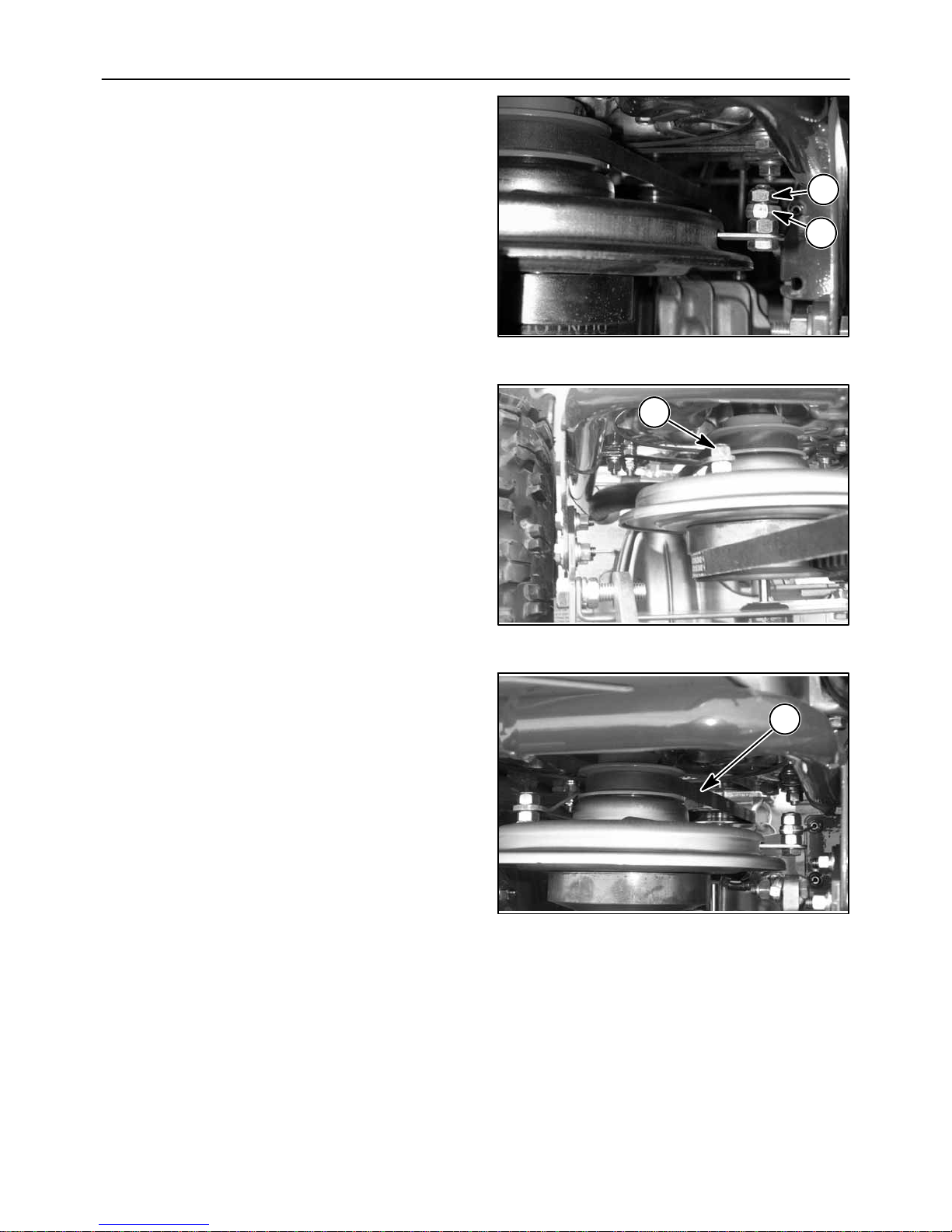
5. Loosen the two retaining bolts, A, that attach the
left axle to the frame. Also, loosen the two
retaining bolts securing the right axle to the
frame.
A
87
6. Loosen bolt, A, that attaches the transmission to
the support
.
A
A
88
A
89
53

7. Adjust dimension at A, from the frame to
centerline of the transmission shaft to 3-5/8 to
3-3/4 inches.
8. Tighten the two axle to frame attaching bolts, A,
for the left axle. Tighten the two axle to frame
bolts on the right axle.
A
90
9. Tighten attaching bolt, A.
A
A
91
A
92
54

10. Installthetransmissionshield,A,andsecurewith
bolts, B.
11. Install the spark plug wire, A, on the spark plug,
B.
B
B
A
93
B
A
12. Start the engine and check for proper operation.
Correct any issues before using the machine.
94
55

TRANSMISSION DRIVE BELT
REPLACEMENT PROCEDURE
Belt Removal
1. Remove the spark plug wire, A, from the spark
plug, B.
2. RemovetheBrushCuttermain drive belt, A, from
the engine pulley as described in the “Remove
Main Drive Belt” section.
B
A
95
3. Remove transmission shield, A, after removing
two bolts, B.
A
96
B
B
A
97
56
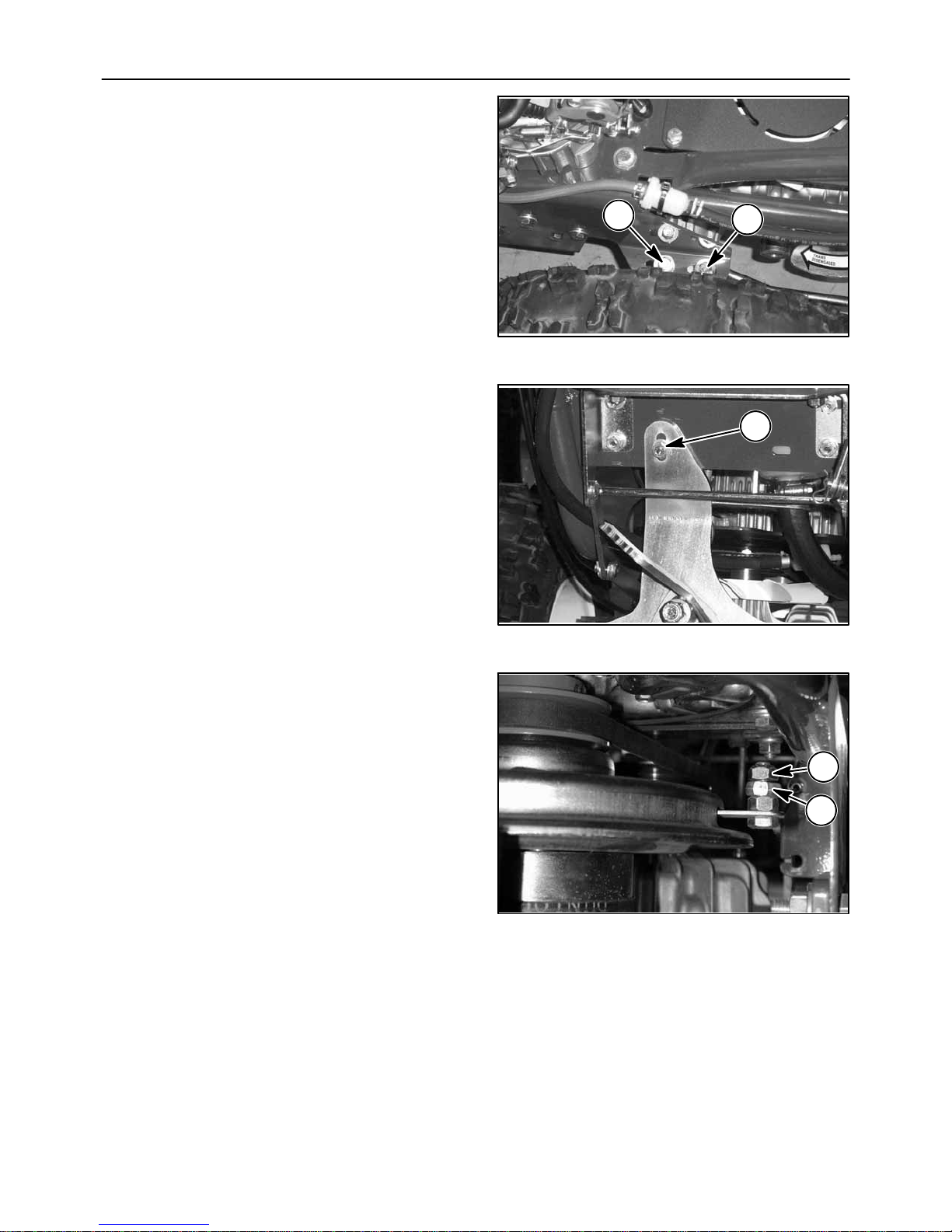
4. Loosen the two retaining bolts, A, that attach the
left axle to the frame. Also, loosen the two
retaining bolts securing the right axle to the
frame.
5. Loosen bolt, A, that attaches the transmission to
the rear frame support
.
A
A
98
A
99
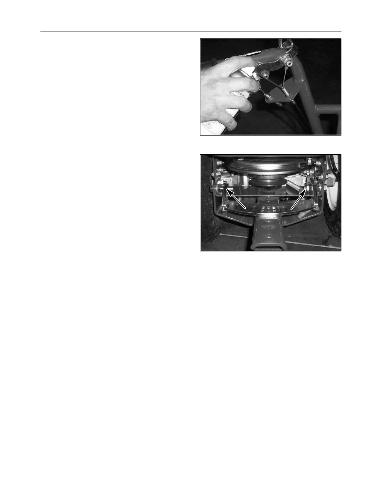
6. Remove the clutch brake cable jam nut, A, then
remove the cable yoke, B, from the stud.
A
B
100
57

7. Remove nut, A, that hold the clutch brake torque
strap then remove the strap from the stud and
swing the strap toward the frame.
8. Remove the transmission belt, A, from the
engine and transmission pulleys and from the
tractor as shown.
A
101
A
9. Adjust dimension at A, from the frame to
centerline of the transmission shaft to 3-5/8 to
3-3/4 inches.
102
A
103
58

10. Tighten the two axle to frame attaching bolts, A,
for the left axle. Tighten the two axle to frame
bolts on the right axle.
11. Tighten attaching bolt, A.
A
A
104
A
105
Belt Installation
12. Installthenew transmission belt, A, and place on
the engine sheave.
A
106
59
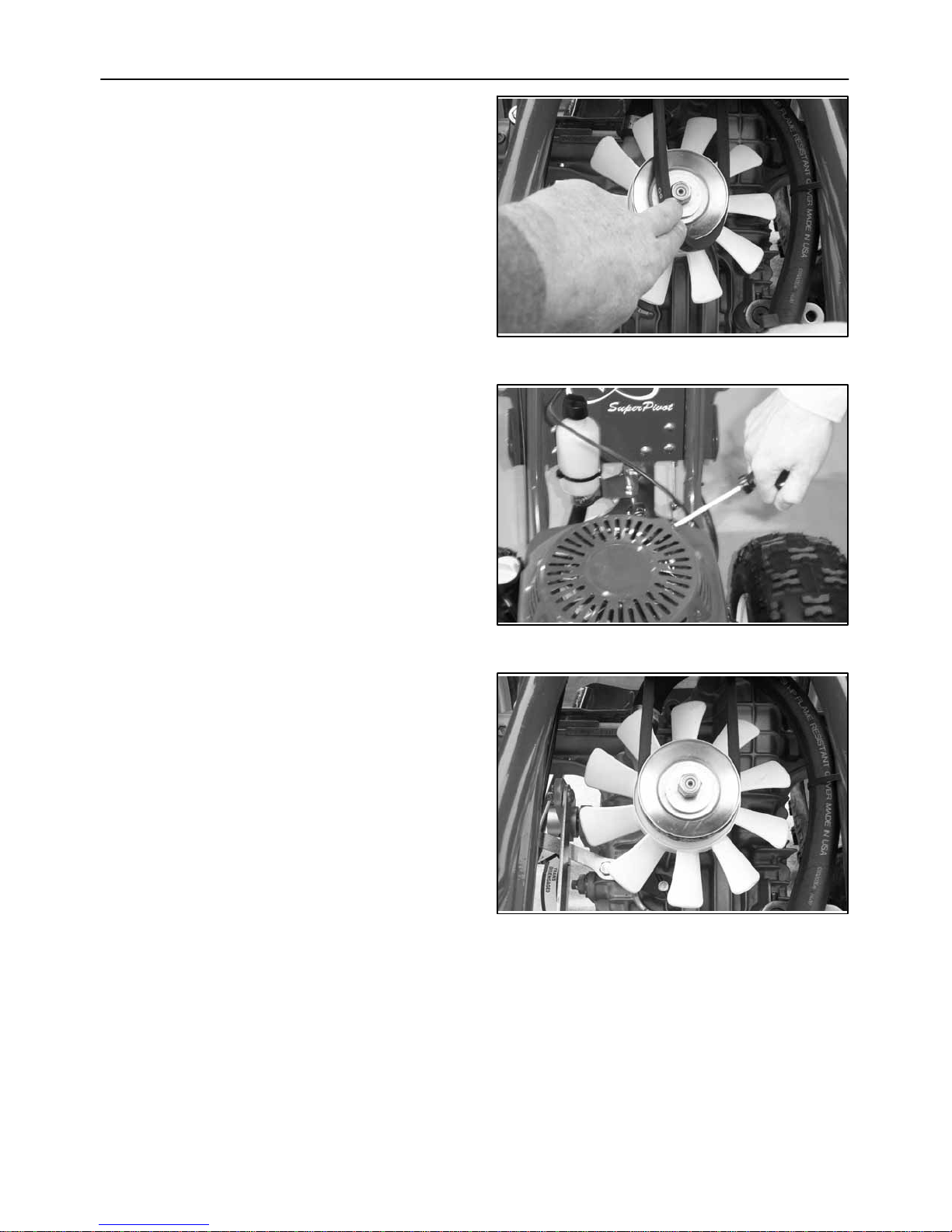
13. Place the belt on the transmission pulley as
shown.
14. Slowly pull on the engine starter rope to place the
belt on the pulley.
NOTE: Spark plug wire must be removed from the
spark plug.
107
15. After the belt has seated on the pulley, pull the
starterrope4timesandcheckthatthebelt is fully
seated on the pulleys, running straight, not
contacting any objects and is not damaged.
Correct as required.
108
109
60
16. Install cable yoke, B, on the stud. Put two drops
ofredLocktite#271onthe threads of thejamnut,
A, then tighten on the stud until there is 1/64 inch
clearance between the jam nut and the yoke.
17. Reinstall the clutch brake torque strap. Put two
drops of red Locktite #271 on the threads of the
jam nut, A, then tighten securely.
A
B
110
A
18. Check that the transmission drive belt, A, is
trackingcorrectly andnotcontactinganyobjects.
111
A
112
61

19. Installthetransmissionshield,A,andsecurewith
bolts, B.
20. InstalltheBrushCutterdrivebelt,A,asdescribed
in the “Replace Main Drive Belt” section.
B
B
A
113
21. Install the spark plug wire, A, on the spark plug,
B.
22. Start the engine and check for proper operation.
Correct any issues before using the machine.
A
114
B
A
115
62

REPLACING THE BLADE
1. Remove the spark plug wire from the spark plug.
2. Support the deck on two jack stands as shown.
116
3. Remove the belt shield and hold the top pulley
with a suitable wrench.
CAUTION: Wear thick gloves when working
around the blade. The blade is sharp and can cut
you.
117
118
63

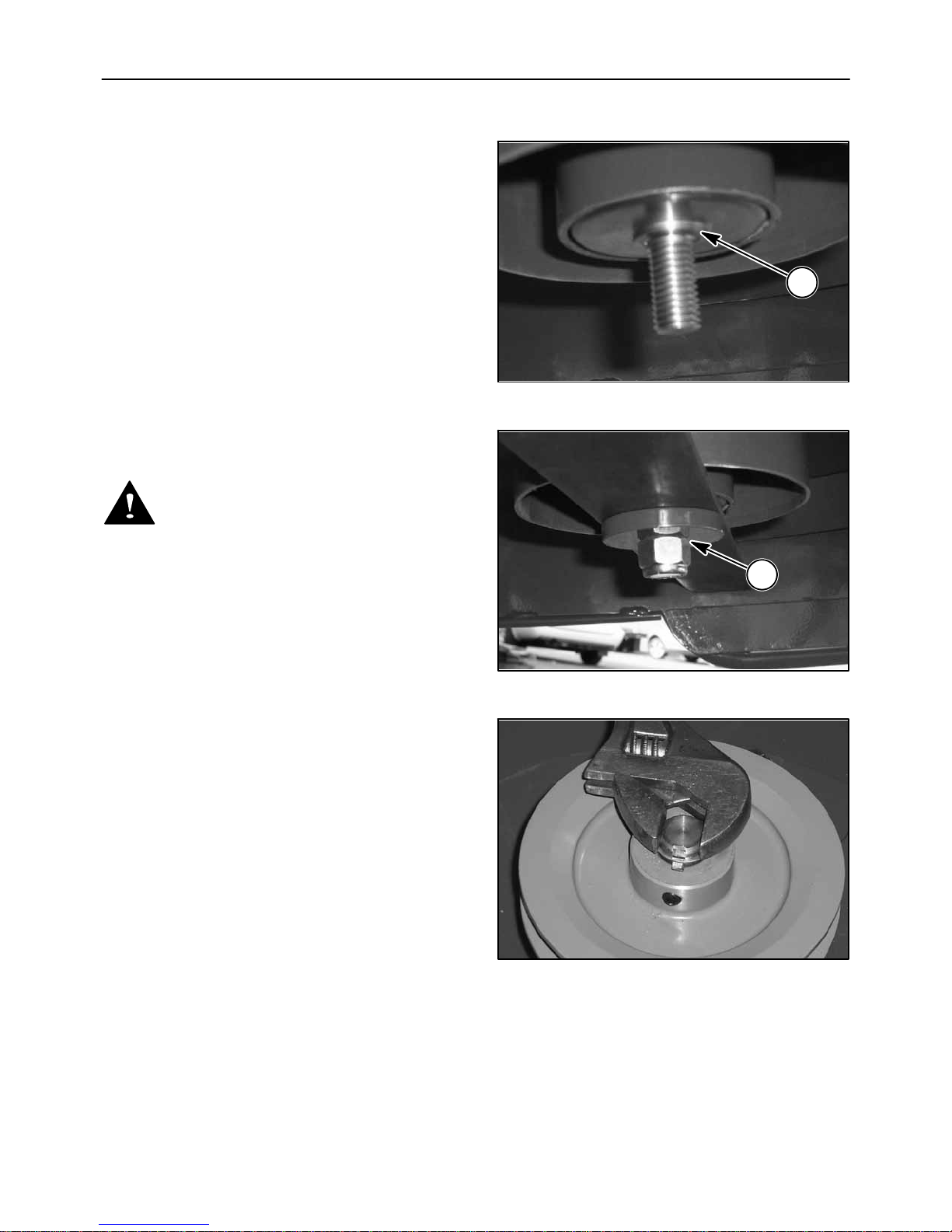
4. Remove the nut and spacer, A, using a 15/16
wrench.
NOTE: The nut is a right hand thread nut.
5. Check the condition of the threads on the shaft
and nut. Replace if there is thread damage or if
the nut is a lose fit on the shaft.
6. Check the pilot lip, A, for damage. Replace shaft
if the lip is damaged.
A
119
A
120
64
BLADE INSTALLATION
1. Install the blade over the pilot lip, A.
2. Install the spacer and nut, A.
3. Torque nut to 90 lbs/ft.
DANGER:Blademustfitoverthepilotlipandnut
must be torqued to 90 lbs/ft. or the blade may
come loose.
A
121
A
4. Hold the flat sides of the shaft with a suitable
wrench as shown while you torque the blade nut
to 90 lbs/ft.
NOTE: Failure to hold the shaft will result in the nut
not being torqued properly.
5. Install spark plug wire and main belt shield.
6. Run the mower.
122
123
65

NOTE: If the mower vibrates or you hear unusual
noisestop themachine immediately.Findthenrepair
the cause of the problem before operating the
mower.
ATTACHING THE BRUSH CUTTER TO THE TRACTOR
SAFETY NOTES
WARNING: Read the entire operator’s manual
before starting any work.
124
Read these instructions thoroughly before
starting any work.
Place the machine on a flat, level and hard
surface.
Wearappropriate protectiveclothing,glovesand
eye protection.
CAUTION: Do not work on the machine when the
muffler is hot.
125
126
66

1. Allow the engine and muffler, A, to cool before
workingaroundtheengineortoremovethemain
belt shield, B.
2. Remove the spark plug wire, A, from the spark
plug, B.
A
B
127
A
3. Remove any attachment from the tractor.
4. Place blocking under the tractor as shown.
B
128
129
67
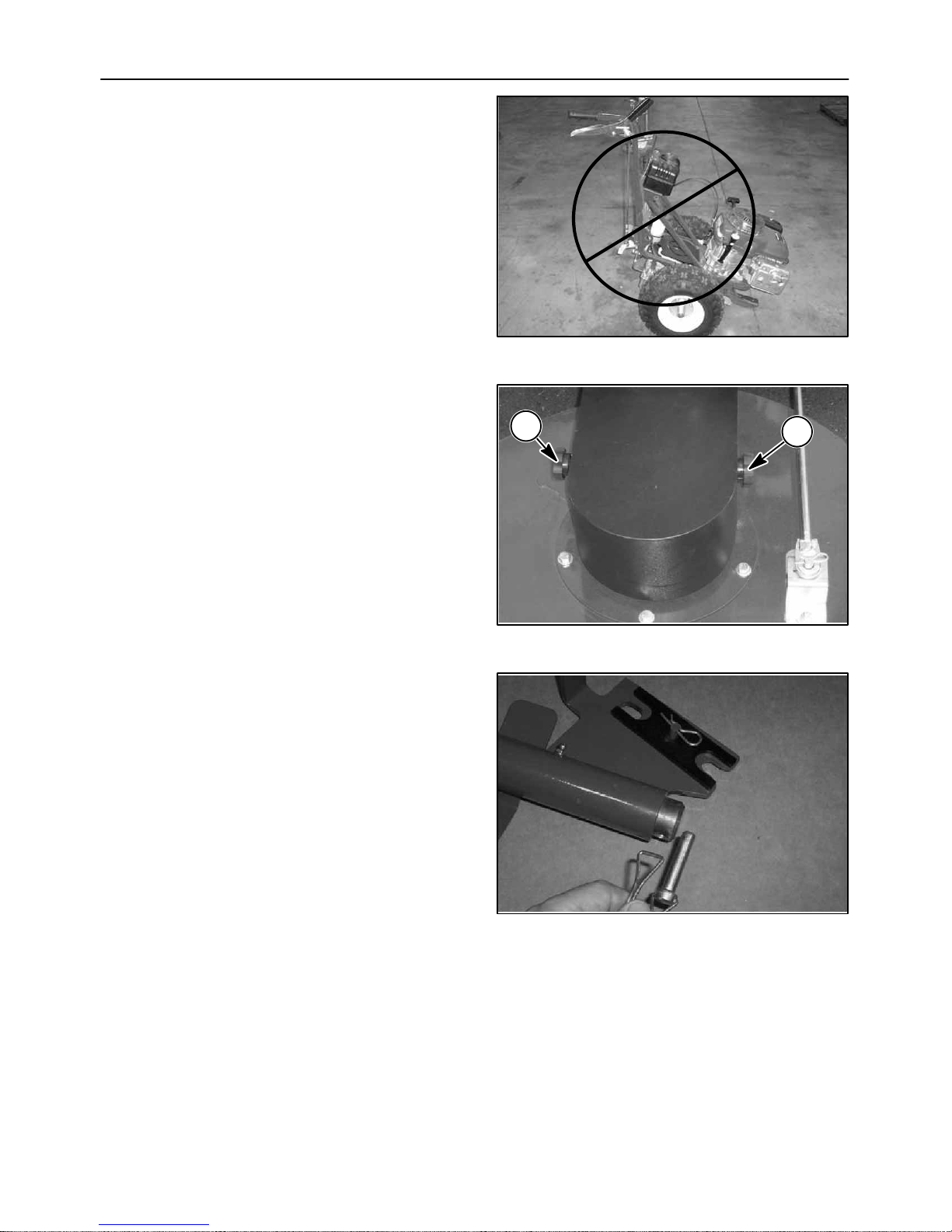
NOTE: Do not park the tractor resting on the tongue.
Oil will fill the cylinder causing the engine to smoke.
5. Remove the two shield attaching knobs, A.
130
6. Remove the pin.
A
A
131
132
68

7. Slide the tube off the rod.
8. Remove pin.
133
9. Slide the mount bracket from the tube.
134
135
69

10. Install the receiver, A, on the tongue.
11. Torque the rear bolt and the front nut to 65 lbs/ft.
A
136
12. Install the lock plate, A, as shown over the bolts.
Note:Ifthelockplatedoesnotfit over the bolt heads,
tighten the hardware until the lock plate fit the
hardware.
137
A
138
70

13. Install the hair pin as shown.
14.Placea2x4under the deck as shown.
139
15. Disconnect the transmission by placing the lever
fully forward as shown.
140
141
71

16. Push the tractor forward and inset the deck pin
fully in the receiver.
17. Insert the pin to lock the deck to the receiver.
142
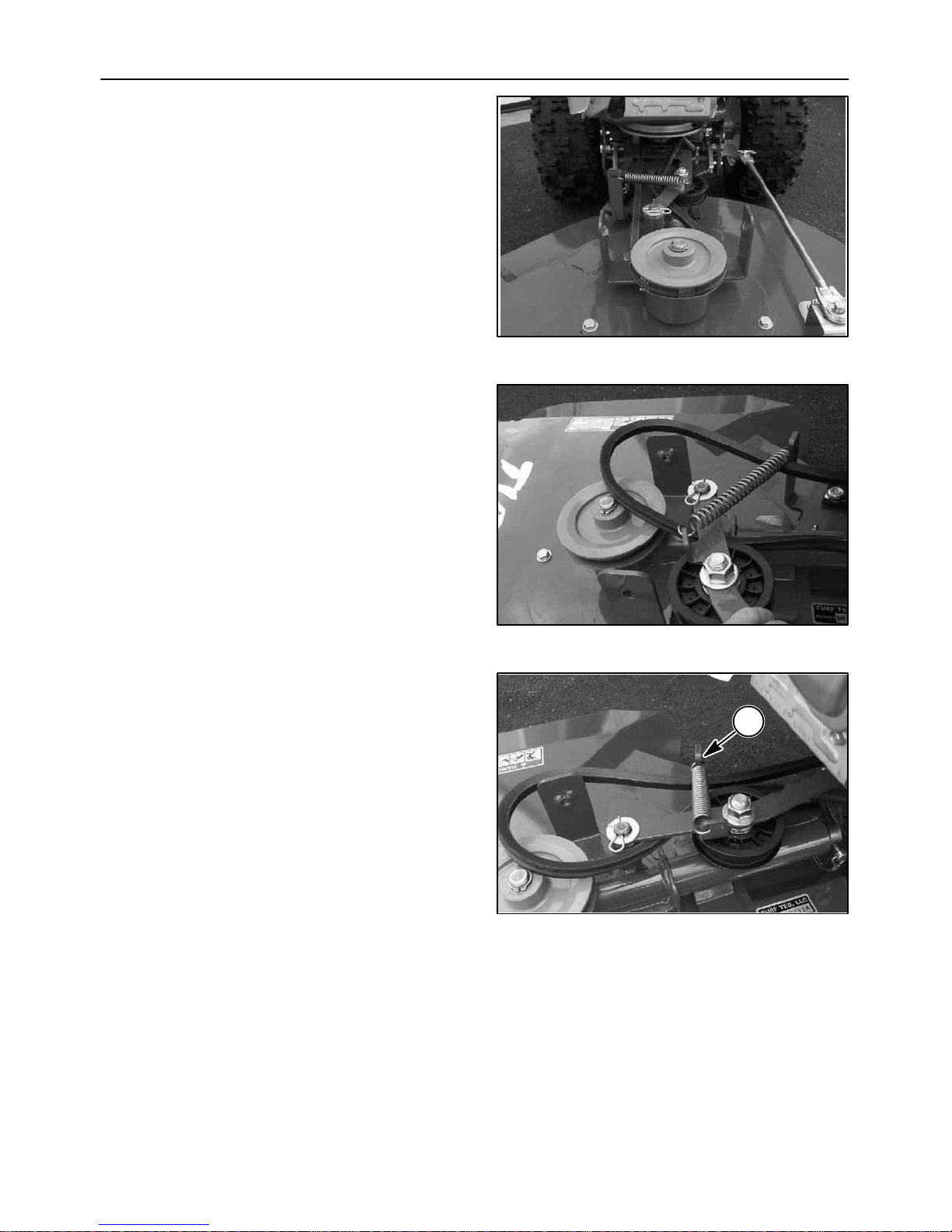
18. Slide belt under the idler.
143
144
72
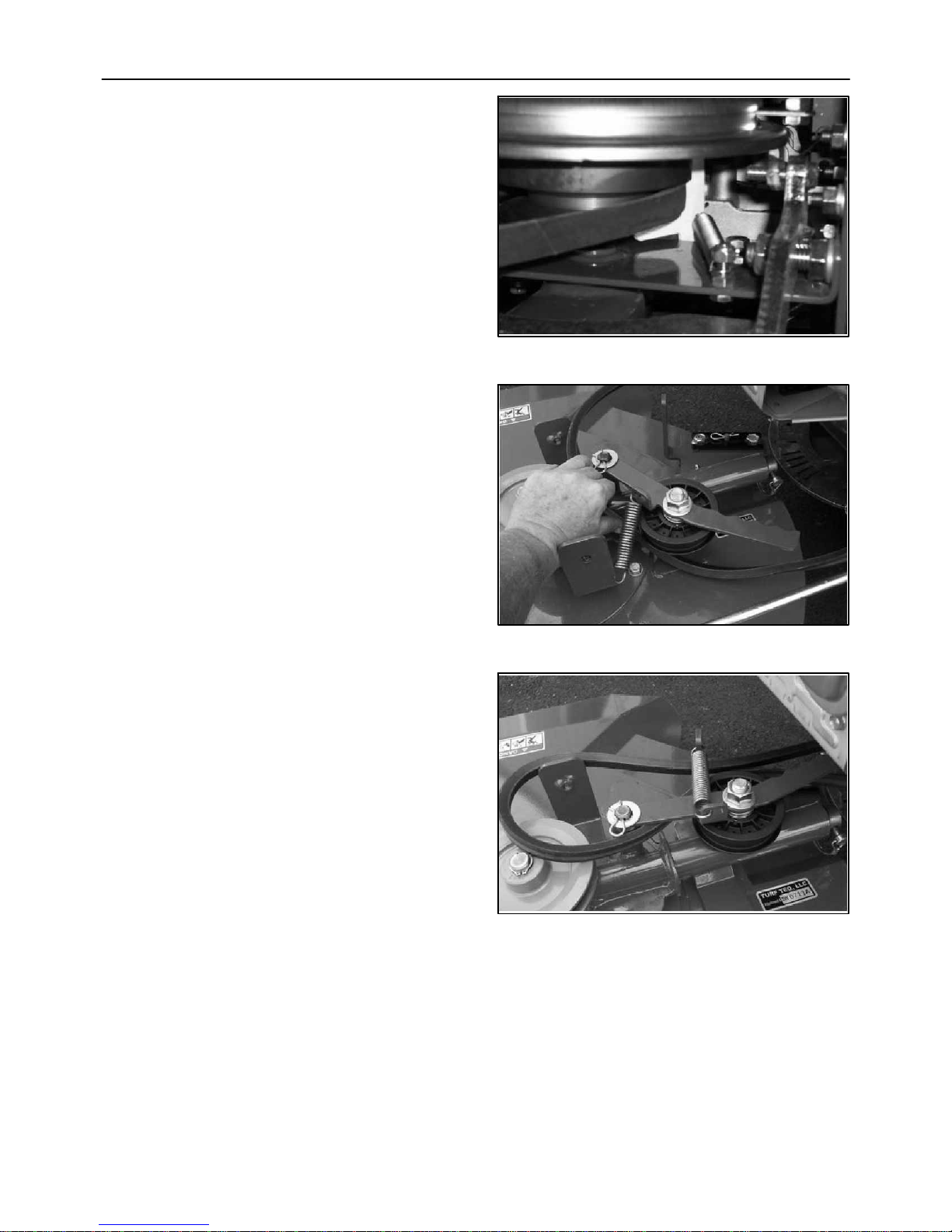
19. Position the white belt idler toward the belt until
the spring pulls it overcenter.
20. Installthebeltbyslidingitbetween the pulley and
the frame.
145
21. Attach the spring to the anchor arm as shown.
146
147
73

22. Pull on idler arm to remove belt tension.
23. Install the belt on the pulley.
24. Releasetheidlerarmand check the belt ifseated
in the pulley.
148
25. Check that your frame has the two holes, A, as
shownforthebrackettoattach.
Note: Iftheholesare notpresent proceed to the next
step.
Note: If the holes are present proceed to step 33.
149
A
150
74
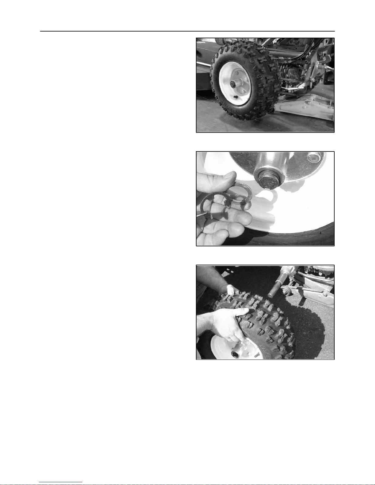
26. Jack up the left side of the tractor.
Note: Useajack stand or blocking under the left axle
housing to support the tractor.
27. Remove the C clip that holds theleftwheelonthe
axle.
151
28. Remove the left wheel and tire.
152
153
75

29. Mark the hole locations as shown.
30. Drill two 11/32 inch holes where the lines
intersect.
31. Reinstall the left wheel, and secure with the C
clip.
2--3/8”
2--3/8”
154
32. Remove the jack and blocking.
155
156
76
33. Installthebracket and tighten the hardware to 25
lbs/ft.
34. Install a flat washer as shown.
35. Install the link arm over the pin.
157
36. Install a flat washer.
37. Inserttheslippin asshowntosecurethelinkarm.
158
159
77

38. Grease the deck pivot point at the zerk shown.
Apply grease until grease pushes out between
the joint.
39. Grease the idler pivot point until grease pushes
out between the joint.
160
40. Grease the deck pivot zerk until grease pushed
out of the joint.
161
162
78

41. Installthebeltshieldandtightenthe two securing
knobs, A.
42. Attach the spark plug wire to the spark plug.
A
A
163
43. Position the transmission level full rearward in
the engaged position detent.
164
165
79

WARNING: Read the entire operator’s manual
before operating the Brush Cutter.
Operate the Brush Cutter and make sure
everything is operating properly.
Correct any problem before using the Brush
Cutter.
166
80

REMOVING THE BRUSH CUTTER FROM THE TRACTOR
WARNING: Read the entire operator’s manual
before starting any work.
Removing the Brush Cutter is the reverse of
installation.
167
1. Allow the engine and muffler, A, to cool before
workingaroundtheengineortoremovethemain
belt shield, B.
2. Remove the spark plug wire, A, from the spark
plug, B.
A
B
168
A
B
169
81

3. Remove the main drive belt as described in the
“Replace Main Drive Belt” section.
4. Support the rear of the deck with blocking.
170
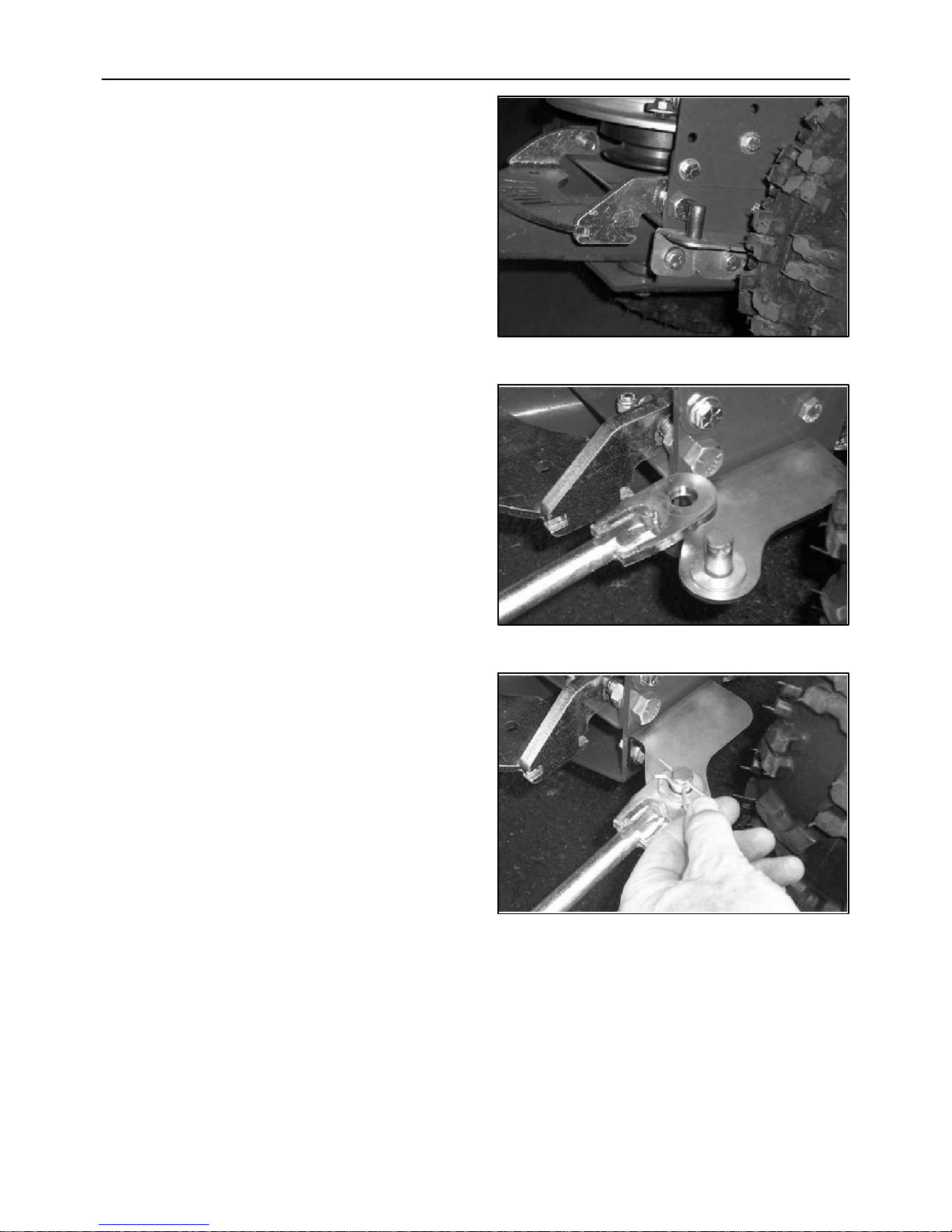
5. Remove the pin from the link arm.
171
172
82

6. Disconnect the link arm from the pin.
7. Remove the pin form the rear of the deck
attaching rod.
173
8. Pullthetractor away from the deck until deck pin,
A, is out of the receiver, B.
174
B
A
175
83

END OF SEASON STORAGE SERVICE
CLEAN THE ENTIRE MACHINE AND
ENGINE
Thoroughly clean the machine and engine then blow
dry with 50 PSI compressed air.
ENGINE SERVICE
1. Refer to the engine manufactures manuals for
specific recommendations and procedures.
2. Drain the fuel tank.
3. Run the engine until the carburator runs out of
fuel and the engine stops running.
MACHINE SERVICE
1. Lubricate all grease point as shown in the
Lubrication Section.
2. Lubricate all linkage pivot points.
3. Spray exposed cables with a fluid lubricant to
prevent binding and rust.
4. Examine belt for damage and replace as
required.
5. Check the condition of all shields and replace as
required.
6. Check safety decals and replace as required.
7. Check all bearing for bearing condition. Replace
any loose bearings.
8. Check condition of the blade and replace as
required.
9. Clean the bottom of the deck to prevent the deck
from rusting.
84

SPECIFICATIONS
ENGINE Honda – GXV390K1 13.0 HP
FUEL TANK 1.0 US Gallon
OPERATING SLOPE Maximum operating slope 20 degrees
TRANSMISSION Hydrostatic infinite variable control
GROUND SPEED 0–4.2mph
WEIGHT 380 Lbs.
DIMENSIONS 42” W x 45” H x 76” L
BLADE WIDTH 26”
DECK WIDTH 28”
CUTTING HEIGHT 2-3/4” or 3-3/4”
DECK OSCILLATING 12 degrees right and left
SKIDS AND PUSH BAR Adjustable for cut height
Replaceable
DRIVES Engine mounted clutch/brake
TIRES Rear = 18 x 6.5 heavy 4-Ply lugged
ATTACHMENT ARM Variable angle 0 to 18 degrees to the left
Deck can be positioned up to 12 inches outside the left handle bar
CONTROLS Variable speed control lever
Implement positioning lever
Differential lock
Park Brake – optional
FRAME Heavy formed tube mainframe
85

BEFORE EACH USE
AFTER EACH USE
1. Check brush cutter daily for loose, bent, broken,
or missing parts.
2. Observe brush cutter’s general condition, noting
points that may need attention.
3. Check blade to be sure no foreign objects such
as wire or weeds are wrapped around it.
4. Make certain drive line shields are in place and
in good condition.
5. During operation, listen for abnormal sounds
which might indicate loose parts, damaged
bearings or other damage. Correct any problem
immediately.
1. Clean all debris from brush cutter especially on
the blade and deck.
2. To prevent rusting, touch up any spots where
paint may have worn off.
3. Store in a clean, dry place.
TROUBLESHOOTING
SYMPTOM POTENTIAL CAUSE REMEDY
Blade does not turn. Tractor attachment clutch is not engaged. Engage tractor Attachment
Drive.
Control and Brake Lever
Obstruction jammed between the rotor and
frame.
Blade stalls too easily. Cutting height too deep. Increase cutting height.
Ground speed too fast. Reduce ground speed.
Clear obstruction from the blade
as detailed in the manual.
Main Drive Belt is slipping. Replace Main Drive Belt.
Blade not sharp. Sharpen blade.
Blade installed backward so blunt end of blade
enters crop first.
Blade not tight on shaft. Tighten nut to 90 LBS/FT.
Main drive clutch is slipping. Adjust main drive clutch cable
Install blade so cutting portion of
the blade enters crop first.
tension.
86


BC02--1009
Printed in U.S.A.
 Loading...