

TurfEx TS-65, TS-65SS Owner's/operator's Manual

This Manual Must be Read Before Operating The Equipment
Owner/Operator’s Manual
FOR MODEL
TS-65/TS-65SS
Madison Heights, Michigan 48071
800-725-8377
www.turfexproducts.com
CUSTOMER COPY

Table of Contents
General Information ..................................................................................................................................................................................... 3
Introduction ................................................................................................................................................................................................. 4
Safety .......................................................................................................................................................................................................... 5
Spreader Assembly Instructions ................................................................................................................................................................ 6-7
Operating Instructions .................................................................................................................................................................................. 8
Spreader Maintainence ................................................................................................................................................................................ 9
Calibration ............................................................................................................................................................................................ 10-11
Warranty .................................................................................................................................................................................................... 12
Assembly Views ......................................................................................................................................................................................... 13
Hopper Assembly Parts Breakdown
Model# TS-65/TS-65SS .................................................................................................................................................................. 14-15
Handle Assembly Parts Breakdown
Model# TS-65 ................................................................................................................................................................................. 16-17
Axle Assembly Parts Breakdown
Model# TS-65 ................................................................................................................................................................................. 18-19
Handle Assembly Parts Breakdown
Model# TS-65SS ............................................................................................................................................................................. 20-21
Axle Assembly Parts Breakdown
Model# TS-65SS ............................................................................................................................................................................. 22-23
Notes .................................................................................................................................................................................................... 24-25
Have a question or need assistance?
Monday through Friday 8:00 AM to 4:30 PM EST
Fax: (248) 691-8378
E-Mail: customercare@trynexfactory.com
Website: www.turfexproducts.com
2
TurfEx Customer Care
(866) 5TURFEX
or (248) 586-3500
© Trynex International 2011 L1193

General Information
T A-200000
CONGRATULATIONS!
The Turfex product you have purchased is an example of turf management product at its fi nest! Your Turfex product ’s, self contained
design is a trademark of all Turfex products. Here’s why...
SIMPLICITY: Fewer moving parts manufactured of higher quality means minimal maintenance for your Turfex product.
RELIABILITY: High impact linear low density polyethelyne hopper, custom engineered powder coated or stainless steel frame.
VERSATILITY: Multi-use capabilities allows spreading of a variety of materials.
WARRANTY: Two years parts and labor from date of installation.
The benefi ts you are about to recognize are that of time, money and effort.
We welcome you to the world of Turfex Performance.
Registration
Record the following information in this manual for quick reference.
Spreader Model Number
Spreader Serial Number
Date of Purchase
Dealer Where Purchased
When ordering parts, the above information is necessary. This will help to insure
that you receive the correct parts.
At the right is a diagram of the ID tag. This tag is located on the frame (where applicable).
Please fi ll out the warranty card with all the necessary information to validate it. This will
also give us a record so that any safety or service information can be communicated to you.
TB-200000
© Trynex International 2011 L1193
3

Introduction
This manual has been designed for your help. It will assist you and instruct you on the proper set-up, installation and use of this spreader.
Refer to the table of contents for an outline of this manual.
We require that you read and understand the contents of this manual completely (especially all safety information) before attempting any
procedure contained herein. Extra copies of Owner/Operator Manuals can be purchased at your Turfex Dealer.
THIS SIGN SHOULD ALERT YOU:
The Society of Automotive Engineers has adopted this SAFETY ALERT SYMBOL to pinpoint characteristics
that, if NOT carefully followed, can create a safety hazard. When you see this symbol in this manual or on the
machine itself, BE ALERT! Your personal safety and the safety of others is involved.
Defi ned below are the SAFETY ALERT messages and how they will appear in this manual:
(RED)
Information that, if not carefully followed,
can cause death!
(ORANGE)
Information that, if not carefully followed,
can cause serious personal injury or death!
(YELLOW)
Information that, if not carefully followed,
can cause minor injury or damage to equipment
4
© Trynex International 2011 L1193

Safety
Before attempting any procedure in this book, these safety instructions must be read and understood by all workers who have any part in the
preparation or use of this equipment.
For your safety warning and information decals have been placed on this product to remind the operator of safety precautions . If anything
happens to mark or destroy the decals, please request new ones from TurfEx.
Remember, most accidents are preventable and caused by human error. Exercising of care and precautions
must be observed to prevent the possibility of injury to operator or others!
Never operate equipment when under the infl uence of alcohol, drugs, or medications that might alter your
judgment and/or reaction time.
Before working with the spreader, secure all loose fi tting clothing and unrestrained hair.
Always wear safety glasses with side shields when servicing spreader. Failure to do this could result in
serious injury to the eyes.
Never attempt to lift a unit with material in it.
Never allow children to operate or climb on equipment.
Always check areas to be spread to be sure no hazardous conditions or substances are in the area.
Always inspect unit for defects: broken, worn or bent parts, weakened areas on spreader.
Remember it is the owner’s responsibility to communicate information on safe usage and proper
maintenance of all equipment.
Always make sure personnel are clear of areas of danger when using equipment.
Never weld or grind on equipment without having a fi re extinguisher available.
Inspect the unit periodically for defects. Parts that are broken, missing or worn out must be replaced
immediately. The unit or any part of it can not be altered without prior written permission from the
manufacturer.
Never use wet materials or materials with foreign debris with any of these spreaders. These units are
designed to handle dry, clean, free fl owing material.
Never leave material in hopper for long periods of time. Be aware that all fertilizers are hygroscopic and will
attract atmospheric moisture and harden up.
© Trynex International 2011 L1193
5
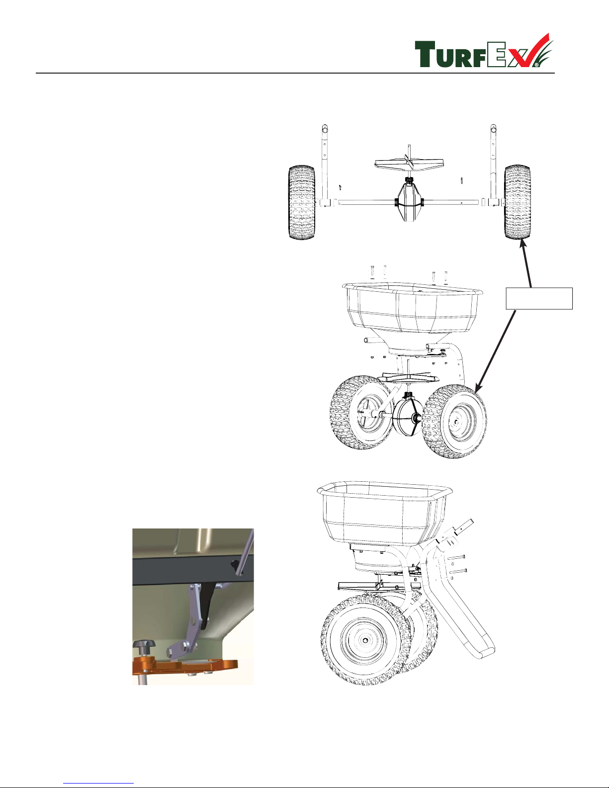
Spreader Assembly Instructions
TS-65/TS-65SS
Step 1: Assemble Axle Assembly
A) Slide shaft collars onto axle toward gear housing.
B) Slide hopper frame onto axle through bushings.
C) Assemble wheels to axle with long cotter key
through drive wheel and
the short cotter key outside free wheel through axle.
D) Snug up axle collars to frame and tighten. Make
sure axle spins freely.
Step 2: Assemble Hopper to Frame
A) Insert spinner shaft through hole in bottom of
hopper.
B) Assemble hopper to frame with (4) bolts
(NOTE: do not tighten).
IMPORTANT - MAKE SURE THAT THE DRIVE
WHEEL IS ON THE LEFT WHEN THE
SPREADER IS BEING PUSHED OTHERWISE
THE SPINNER WILL SPIN CLOCKWISE THUS
MAKING THE SPREAD PATTERN INEFFECTIVE.
Drive Wheel
Step 3: Assemble leg to hopper frame with (4)
bolts (NOTE: do not tighten). Then attach linkage
to frame stand. (see image below)
6
© Trynex International 2011 L1193
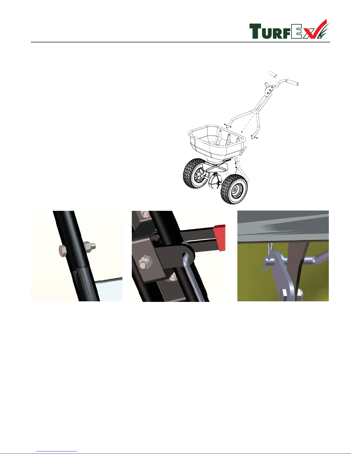
Spreader Assembly Instructions (con’t)
TS-65/TS-65SS
Step 5: Assemble handle assembly to leg
A) Slide handle onto leg and fasten with (2) bolts.
(see fi gure1)
B) Insert rod into upper control handle. (see fi gure 2)
C) Insert rod end into gate linkage and lock in place
with hair pin clip (see fi gure 3)
Figure 1
Figure 2
Step 6: Spin tires and make sure spreader is running smoothly.
Step 7: Tighten all bolts.
Figure 3
Step 8: Attach material stir wire to spinner shaft inside hopper.
Place screen inside hopper put hopper cover on.
© Trynex International 2011 L1193
7

Operating Instructions
TS-65/TS-65SS
SPREADER LOADING
Capacity: 1 1/2 Cubic Ft Hopper
WARNING – Do not overload spreader. Weights of material are an average for dry materials.
Material Weight Per Cubic Ft.
Fertilizer See product information on bag or bulk materials that you are using
• Warning – Never remove spreader from vehicle with material in it as this could cause damage to the frame assembly.
• Warning – Never leave materials in hopper for long periods of time, fertilizers are hygroscopic and will attract atmospheric
moisture and harden up.
SPREADING TIPS
• For a wider pass, increase walking pace.
• For a heavier pass, walk slower .
• Use care when operating spreader near pedestrians.
• Calculate spread pattern when near vegetation.
8
© Trynex International 2011 L1193
 Loading...