

Page 1

™
™
™
™
™
60” Inch Seeder
®
OPERATOR’S MANUAL
MAINTENANCE MANUAL
PARTS LIST
®
TURFCO
60” Inch Seeder
Product Number 85851
Starting Serial Number P00801
PATENT PENDING
Manual Number 665365 Rev B
DANGER -
THOSE WHO USE AND MAINTAIN THIS MACHINE SHOULD BE TRAINED IN ITS
PROPER USE, WARNED OF ITS DANGERS, AND SHOULD READ THE ENTIRE MANUAL
BEFORE ATTEMPTING TO SET-UP, OPERATE OR SERVICE THE MACHINE.
IF INCORRECTLY USED THIS MACHINE CAN CAUSE SEVERE INJURY.
TURFCO MFG. INC.
1655 101st. Avenue NE • Minneapolis, MN 55449-4420 USA
Phone (763) 785-1000
FAX (763) 785-0556 • www.turfco.com
•
2011 Turfco Mfg., Inc.
Page 2
™
™
TURFCO
SS85851-01REVA
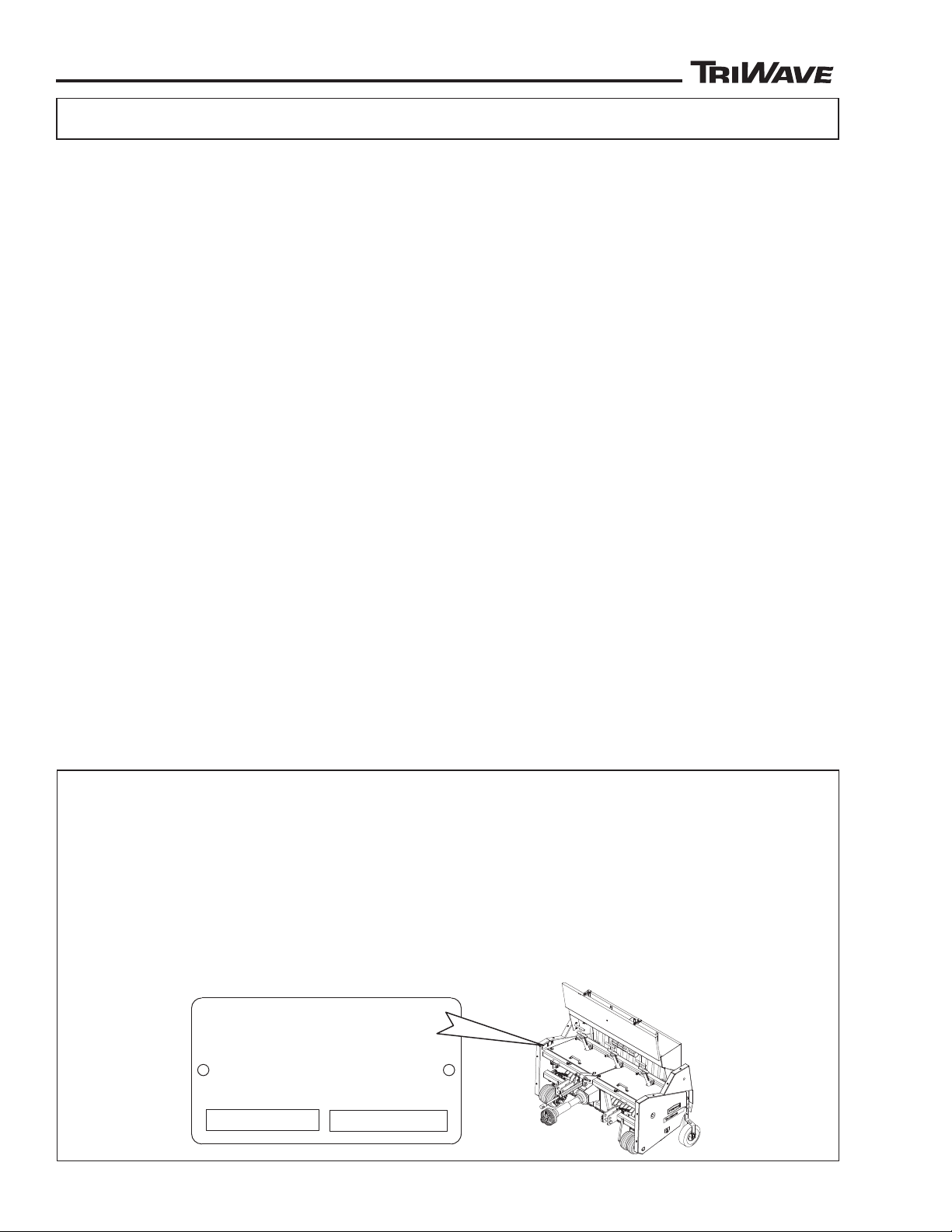
TURFCO MFG., INC
1655 101ST Avenue NE
Minneapolis, Minnesota
USA 55449-4420 www.turfco.com
(763) 785-1000 FAX (763) 785-0556
PRODUCT SERIAL
TABLE OF CONTENTS
All specifications, information, illustrations or photos in this manual are
based on the latest information at the time of printing. The right is reserved to make changes without notice.
Product Records ......................................................................................................................2
Specifications ...........................................................................................................................3
Registered Trademarks and Patents ........................................................................................3
How To Obtain Parts And Service ............................................................................................3
Recognizing Safety Warnings And General Safety Practices .................................................4
Setup And Installation ...............................................................................................................6
Description .............................................................................................................................10
Operation
Pre-Operation Check List and Work Site Preparation .......................................................13
Raising Storage Wheels ....................................................................................................13
Ground Operating Speed and Maximum Angle Of Operation ...........................................13
Loading Seed Hopper ........................................................................................................14
Setting Seed Gate Dial ......................................................................................................14
Operating Seed Gate Control Handle ................................................................................14
Setting Blade Depth Adjustment ........................................................................................15
Setting Down Pressure Adjusters ......................................................................................15
Operation ...........................................................................................................................16
In Operation Quality Checks ..............................................................................................16
Decals ....................................................................................................................................17
Operator Daily Inspection .......................................................................................................18
Storage ...................................................................................................................................18
Trouble Shooting Table ...........................................................................................................19
Service
Seed Distribution Box Height Adjustment .......................................................................... 20
Lubrication .........................................................................................................................22
Chain Adjustment ..............................................................................................................23
Cutting Head Removal And Blade Replacement ............................................................... 24
Jackshaft Bearings and Collar Adjustment ........................................................................27
Part Lists ................................................................................................................................28
Table of Contents
Product Records
IMPORTANT: Record the information from the serial number plate of your TriWave 60” Seeder. It will be
necessary to furnish your Model Designation, Product Number, and Serial Number when ordering parts.
Model Designation TriWave 60” Seeder
Product Number 85851 Serial Number ________________________
Date Purchased __________________________________________________________________
Purchased From __________________________________________________________________
2
85851 Rev B
Page 3

™
™
SPECIFICATIONS
Specifications
Intended Use: The TriWave Seeder is intended to be USED ONLY to overseed grass seed on existing
turf at sports turf fields and on golf courses. The TriWave is not intended to be a primary seeder and is
not intended to be used to seed areas without existing turf. The TriWave Seeder is intended only to be used
with grass seed. The TriWave Seeder is NOT intended to be used for any purpose other than to apply grass
seed to the turf. The TriWave Seeder is not intended to be used for the application of fertilizers or lawn foods.
The TriWave Seeder is not intended to be used as a sod cutter, aerator, rototiller, compaction roller, or any
other type of soil preparation or turf maintenance tool. Use of the TriWave Seeder is intended at a properly
prepared worksite where deficiencies have been corrected to avoid injury and/or damage to the machine. The
TriWave Seeder is not designed for or intended to accept riders.
TriWave Seeder Dimensions:
Width ...................................................................1.88 Meter (74” Inches)
Height (On Ground In Operating Position) ..........1.3 Meter (51” Inches)
Length (Without PTO Shaft) ................................1.02 Meter (40” Inches)
Seed Hopper Capacity ............................................0.135 Cubic Meter (8251 Cubic In. Or 4.77 Cubic Ft.)
Approximately 45.35 Kg. (100 Pounds) of Grass Seed
Seed Application Pattern ........................................30 Rows Spaced 38.1 mm (1-1/2” inches) apart
Seed Application Width ..........................................1.52 Meter (60” Inches)
Seed Gate .................................................................Manually Operated, Variable Opening
Ground Operating Speed .......................................Up To 8.85 km/h (5.5 MPH)
Productivity .............................................................8,094 Square Meters At 5.63 km/h
(2 Acres - 9680 Square Yards at 3.5 MPH)
Cutting Heads ..........................................................3 Heads, Independently Floating
Blade Assembly .......................................................3 Blade Sets, Total 30 Blades
Blade Assembly Operating Depth Range .............0 to 34.9 mm (0 to 1-3/8” Inch)
Tractor/Horsepower Requirements .......................26.1 Kw Minimum to 44.7 Kw Maximum
(35 HP to 60 HP)
Drive .........................................................................540 PTO (Tractor)
Hitch Type ................................................................Category 1 or Category 2 Three-Point Hitch
Weight (Hopper Empty) ..........................................521.6 Kg (1150 Pounds)
Maximum Weight With Seed Hopper Full .............Approximately 567 Kg (1250 Pounds)
Registered Trademarks and Patents
Patent Pending
TriWave™ is a Trademark of Turfco Manufacturing. TURFCO® is a registered Trademark of Turfco Mfg., Inc.
Gandy® is a registered trademark of the Gandy Company.
Seed Gate Patents are Property of the Gandy Company.
How To Obtain Parts and Service
To order parts, or to arrange repair service, contact
the nearest authorized TURFCO dealer. For a list of
a u t h o r i z e d TURFCO dealers in your area, or for
a d d i t i o n a l information regarding the TriWave
Seeder, direct inquiries to:
TURFCO Mfg. Inc.
1655 101st. Avenue North East
Minneapolis, MN. 55449-4420 USA
Telephone (763) 785-1000
FAX (763) 785-0556
E-mail - [email protected]
Internet - www.turfco.com
85851 Rev B
To ensure safety and proper operation, always purchase
genuine TURFCO replacement parts from
an authorized TURFCO dealer. Re pl a ce me n t
parts from other sources may damage the TriWave
Seeder and/or create a safety hazard. Always refer
repairs to properly trained service personnel.
DO NOT ALTER the TriWave Seeder in any manner.
Unauthorized alterations may affect its operation,
performance, and may result in injury or death to the
operator as well as other individuals in the work area.
3
Page 4
™
™
Recognizing Safety Warnings Used In Manual
LOOK FOR THE SAFETY HAZARD WARNING SYMBOL
The symbol is used to alert the operator of safety hazards.
It is used in conjunction with the words DANGER, WARNING, and CAUTION.
“DANGER” identifies immediate hazards which will result in serious injury or death.
“WARNING” identifies potential hazards which could result in serious injury or death.
“CAUTION” identifies hazardous situations which may result in minor injury and/or could result in
damage or destruction of equipment.
WARNING CAUTION
DANGER
SAFETY
General Safety Practices
Safety on the job should always be a top priority.
Training and experience are important factors in the safe
operation of equipment. Please consider the following
information and realize that safe operation is a matter
of using common sense as it relates to the machine, its
maintenance, the operator, the training, and the operating
conditions. These are general safety instructions that
apply to most turf maintenance equipment.
This list includes many, but not all, general
safety instructions as they relate to turf
equipment. Common sense must always be
used to determine the safest way to operate a
machine under specific conditions.
TRAINING:
Always read the manual before operating a machine for
the first time.
Always read the warning decals before operating a
machine for the first time.
Always check the location and use of each control before
operating a machine for the first time.
Practice operating the machine in a safe area with no
obstructions until becoming familiar with the controls.
If you have questions, ask your supervisor or call the
factory.
CLOTHING:
Cloths should be snug fit. Loose fitting clothing is
hazardous because it may get caught in the mechanism
during service or operation.
Remove jewelry before operation. Again, jewelry may
get caught in the mechanism.
Wear shoes that will protect your feet. In most cases,
sneakers do not protect and do not provide the protection
of leather shoes or boots. Steel toed safety shoes should
be considered for many situations.
Hard Hat: The use of a hard hat should be considered
4
when using equipment on a golf course. The danger of
being hit by a golf ball should be a major concern as well
as protection while operating under trees .
Eye Protection: Safety glasses and/or face shields should
be considered when operating, as well as working in
close proximity to high speed rotary equipment. Watch
for rotary mowers, edgers, brush and string trimmers.
Rotary mowers can throw debris at speed up to 200
MPH.
Hearing: If the noise level of the equipment is too loud,
consider the use of ear protection.
Do not use stereo headsets during operation. This is a
distraction that may lead to an accident. Headsets also
make it difficult to hear other people and equipment
while operating in the work area.
Respirators: When operating in dusty, windy conditions,
wear a respirator. This is also an important consideration
if operating equipment while spraying chemicals and
fertilizers.
Gloves: Use gloves when handling sharp or hazardous
objects.
THE OPERATOR:
The operator should never use a machine while under
the influence of alcohol or drugs. The operator should
be aware of the hazards of working in the sun and
should take proper precautions to avoid heat stress and
dehydration. Use sun screen products when necessary.
The operator should never attempt to ride a machine
that is not designed for that propose. Do not allow others
to ride a machine that is not designed for passengers.
Care should always be taken when mounting and
dismounting a riding machine. Prevent injuries and falls
by making sure the operator does not slip. Unless it is
an emergency, do not jump off a machine. Injury may
result when an operator’s foot slips trying to jump from
a machine.
Do not operate any equipment at unsafe speeds.
Speeds should be reduced when turning or operating
85851 Rev B
Page 5

™
™
SAFE-13
SAFETY
SAFE-14
on slopes. The operator must use common sense to
determine a safe speed based on the equipment, the
load, the slope, the surface, and other conditions that
may affect safe operation.
The operator must be aware of the conditions around
the area. Be careful to observe other people and
machines.
Beware of slippery conditions. Wet turf can be
encountered on slopes, when turning or stopping, or
at higher speeds.
Keep hands and feet away from cutting devices and
drive components. Shut off the engine and remove the
key or ignition wire when servicing cutting devices or
drive components.
If required to lift, an operator should ask for help if the
object is too heavy. The operator should lift with his or
her legs instead of the back. Care should be taken to
avoid twisting the back while lifting a heavy load.
Never allow children to operate the machine.
THE MACHINE:
Do not modify the machine in any manner. Always
check the machine to make sure it is in good working
order.
Do not place hands or feet near moving or rotating
parts. Inspect to insure that all guards are in place. Do
not operate a machine without all guards in place.
Check to assure that all controls are in good operating
condition. Make sure the brakes are operating
properly.
Do not overload machinery. The components
are designed for certain weights and capacities.
Overloading machine will cause unsafe conditions.
Shut off the engine before servicing the machine.
Check machines on a level area. Machines on a slope
may roll when the engine is off.
Refer unfamiliar repairs and adjustments to mechanics
that have been trained to do them properly.
Replace decals that have become damaged or
illegible.
EQUIPMENT WITH ENGINES:
Prevent accidental starting by removing the spark
plug wire when servicing the engine or the equipment.
Disconnect the negative wire from the battery terminal
if the engine is equipped with an electric starting
system.
Do not strike the flywheel with a hammer or any hard
object. This may cause the flywheel to shatter in
operation. Use the correct tools to service the machine.
Pull the starter cord slowly until resistance is felt. Then
pull the cord rapidly to avoid kickback and to prevent
hand or arm injury.
Do not run the engine in an enclosed area. The exhaust
gases contain carbon monoxide, an odorless and deadly
poison. Engine Exhaust Contains Chemicals Known
to the State of California to Cause Cancer, Birth
Defects or Other Reproductive Harm
Do not store, spill, or use gasoline near an open flame,
nor near an appliance like a stove, furnace, or water
heater that uses a pilot light or can create a spark.
Do not refuel indoors or in an unventilated area. Check
the fuel level. Do not over fill. Do not add fuel while the
machine is hot because spilled fuel may cause a fire.
Use fresh gasoline. Stale fuel can gum the carburetor
and can cause leakage. Check the fuel lines and fittings
frequently for cracks and leaks. Replace if necessary.
Do not remove the fuel tank cap or fill fuel tank while the
engine is hot or running. Allow the engine to cool before
refueling.
Do not operate the engine if gasoline is spilled or when the
smell of gasoline is present or other explosive conditions
exist. Move the equipment away from the spill and avoid
any ignition until the gasoline has evaporated.
Do not transport the engine with fuel in the tank.
Do not start the engine with the air cleaner and/or the air
cleaner cover removed.
Do not choke the carburetor to stop the engine.
Whenever possible, gradually reduce the engine speed
before stopping.
Do not tamper with the governor springs, links or other
parts to increase the engine speed. Run the engine at
the speed set by the equipment manufacture.
Do not check for a spark with the spark plug removed.
Use an approved tester. Do not crank the engine with
the spark plug removed. If the engine is flooded, place
the throttle in fast and crank until the engine starts.
Keep the cylinder fins and the governor parts free of dirt,
grass, and other debris which can affect engine speed.
Do not operate the machine without a muffler. Inspect
the muffler periodically and replace it if it is leaking or
worn. If necessary, replace it with correct muffler. Do
not touch a hot muffler, cylinder, or fin. It may cause
burns. Do not operate the engine with an accumulation
of grass, leaves, or other combustible material in the
muffler area.
Do not use the engine on any forest covered, brush
covered, or grass covered unimproved land unless
a spark arrester is installed in the muffler. The spark
arrester must be maintained in working order by the
operator. In the State of California, the above is required
by law (Section 4442 of the California Public Resources
Code). Other state may have similar laws. Federal laws
apply on federal lands.
85851 Rev B
5
Page 6

™
™
SETUP AND INSTALLATION
WARNING
SAFE-06
WARNING
TURFCO
AS85851-06REVA
THREE-POINT
HITCH
STORAGE WHEELS
INSPECT
INSIDE OF
SEED BOX
WARNING
Setup and Installation
TO AVOID SERIOUS INJURY,
Read and Understand the Entire
Operator Manual For the T
and the TriWave Seeder Before
Operating.
TRACTOR REQUIREMENTS
The TriWave Seeder is designed to be attached
to and powered by a tractor. The tractor must
meet the following specifications:
● Minimum 26.1 Kw (35 horsepower) to Maximum
44.7 Kw (60 horsepower) rating.
540 PTO
●
● Gearing to provide engine speed (RPM) to
produce PTO power and RPM while not
exceeding 8.85 Km/h (5.5 MPH).
Category 1 or Category 2 Three Point Hitch
●
equipped to lift and tow 567 Kg. (1,250
Pounds).
Adequate Brakes to control and stop a hitched
●
load of 567 Kg. (1,250 Pounds).
ractor
to the hitch and drive system on the TriWave
Seeder. Safe movement can only be done with
proper equipment.
tractor must have an appropriate three point
The
hitch to attach to the TriWave Seeder. The TriWave
Seeder
is equipped to accept either a Category 1
or Category 2 three point hitch. Heavy-duty hitch
components are strongly recommended for your
tractor.
The Tractor Must Be Equipped With an
Adequate Category 1 or Category 2 Three
Point Hitch, Rated for Proper Lifting and
Carrying Capacity
, and Have Adequate
Functional Brakes.
When Properly Loaded, the T
riWave Seeder
can Weigh 567 Kg (1,250 Pounds).
Attach Only To a Properly Rated Tractor. Always
use the proper size tractor to move the TriWave
Seeder
, even if moving only short distances. Using
improper hitching methods may cause damage
6
85851 Rev B
Page 7
™
™
AS85851-03REVA
FIGURE 1
CATEGORY 1
CATEGORY 2
UPPER LINK
STORAGE WHEELS (SHOWN IN LOWERED “STORAGE” POSITION)
SEED
DISTRIBUTION
BOXES
SEED
BOX
UPPER MOUNT
LOWER MOUNT
SETUP AND INSTALLATION
SAFE-14
HITCHING TO THE TRACTOR
SAFETY FIRST!!
To Avoid Serious Injury,
Wear the Appropriate Personal
Safety Gear.
Use Caution When W
orking Near Moving
Parts and Rotating Parts.
ork Safely and Follow All Safety Warnings
W
In TriWave Seeder Operators Manual and the
ractor Operators Manual.
T
Do Not Modify The T
riWave Seeder Or The
PTO Shaft To Hitch To The Tractor.
Verify that the tractor meets the requirements
to safely attach and power the TriWave Seeder.
Refer to the section “Tractor Requirements”.
STEP 1. Inspect the inside of the seed box.
Remove anything remaining from shipping,
manufacturing, or previous use.
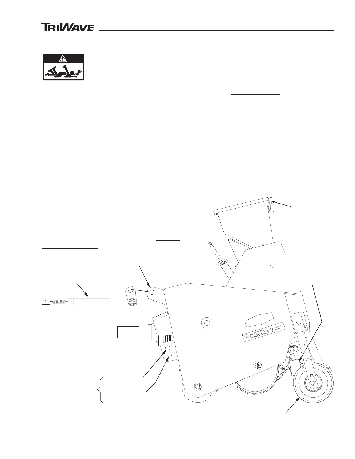
STEP 3. (See Figure 1) Align the tractor to the
TriWave Seeder’s three-point hitch mounts.
● Shut off the tractor engine and set the
brakes.
Tractors PTO must be disengaged
●
● Tractors draft control off.
● The tractors rear lower sway stabilizers should
be set to keep the seeder centered and in line
with the tractor.
STEP 4. (See Figure 1) Use hitch pins to attach
tractor’s lower arms to the TriWave’s lower
the
mounts. Refer
to Figure 1 for proper location of
Category 1 or Category 2 lower mounts.
STEP
Seeder rear storage wheels. DURING HITCHING,
the rear storage wheels should be in the lowered
“storage” position.
2. (See
Figure 1) Check the TriWave
85851 Rev B
7
Page 8
™
™
SETUP AND INSTALLATION
AS85851-02REVA
FIGURE 2
B: THREAD LINK IN OR OUT TO REACH TRACTOR
A: PUSH UPPER LINK BACK TO SEEDER
UPPER LINK
TRIWAVE TOP MOUNT
CHECK LOCKING
HARDWARE ON SEEDER END
CHECK
GUARDS
ASSEMBLE
PTO SHAFT
TRACTOR
END
SEEDER
END
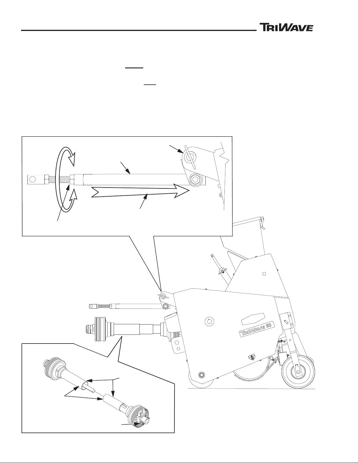
STEP 5. (See Figure 2) Install the upper link to
the TriWave.
● The link should be located below
the
TriWave top mount.
● Use a hitch pin to attach the link to the first
(outside) hole on the
TriWave’s top mount.
STEP 6. (See Figure 2) Attach upper link to
tractor.
● Push the upper link back against the
TriWave.
● Thread end out (or in) until the upper link
reaches the tractor.
● Choose a tractor hitch hole that will set the
TriWave’s upper link as level with the ground as
possible. Avoid
interference with any tractor
guards or components
● Use a hitch pin to attach to the tractor
.
8
85851 Rev B
Page 9
™
™
AS85851-04REVA
23-5/8” INCHES
(600 mm)
MAXIMUM LENGTH
FIGURE 3
16-1/2” INCHES
(419 mm)
MINIMUM LENGTH
AS85851-05REVA
FIGURE 4
STORAGE WHEELS IN
RAISED “OPERATING POSITION”
PACKER WHEELS
SETUP AND INSTALLATION
SAFE-14
DANGER
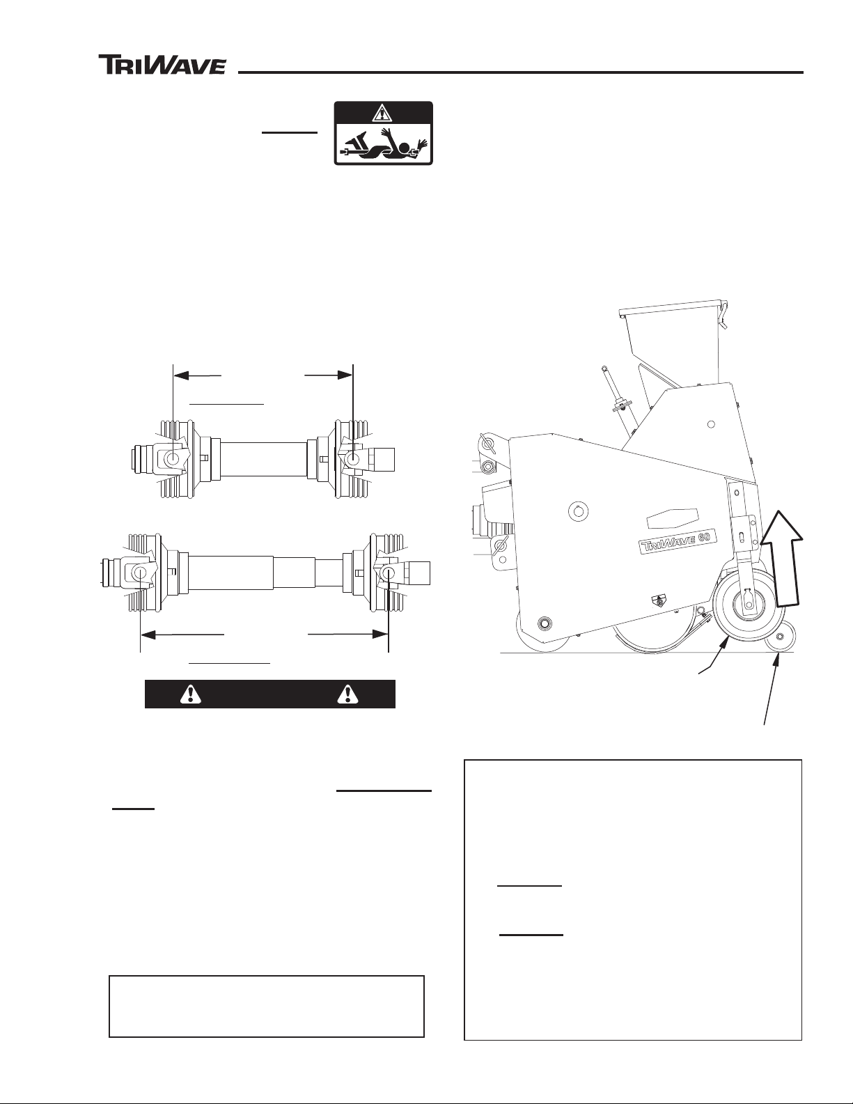
STEP 7. (See Figure 3) Attach
PTO shaft to tractor. Do Not
remove
any guards from the
PTO shaft or the TriWave to
install.
Assemble PTO shaft halves together. Check
●
PTO shaft guards for free movement.
● Install PTO shaft with TriWave lowered.
● Ensure that PTO locks to tractor. Check lock
on TriWave end.
● Check the minimum and maximum operating
dimensions for the PTO shaft.
STEP 8. (See Figure 4) Raise rear storage
wheels.
Start tractor, lift seeder and move to a turf
●
covered area.
Move the TriWave rear storage wheels into
●
the raised “operating” position.
NOTE: To protect the blades, the rear storage wheels
must be returned to the lowered “storage” position when
the seeder is unhitched or lowered over a hard surface.
STOP!!
IF THE PTO SHAFT CANNOT BE INSTALLED
WITHIN THE MINIMUM/MAXIMUM
DIMENSIONS, THE PT
USED WITH THE TRACTOR AND SEEDER.
ANOTHER PT
LENGTH AND GUARDING MUST BE USED
BEFORE OPERATING THE SEEDER.
If the PTO shaft can not be installed because it
will not fit between the TriWave and the tractor,
(space is less than 16-1/2”) extensions for the
TriWave lower mounts are available to reposition
the TriWave further away from the tractor.
CONTACT TURFCO FOR INFORMATION
ON AVAILABLE LOWER THREE POINT
85851 Rev B
O SHAFT WITH SUITABLE
MOUNT EXTENSIONS.
O SHAFT CANNOT BE
FINAL ADJUSTMENT
STEP 9. Adjust Upper Link. Move the tractor
and seeder over a turf covered area
● SLOWL
the cutting head to settle into the turf.
● SLOWL
cutting head seed distribution boxes.
If the seed distribution boxes touch and dig
●
into the turf during raising, shorten the length
of the upper link.
Y lower TriWave to the turf. Allow
Y raise TriWave while observing
9
Page 10
™
™
SEED
GATE
DIAL
SEED GATE
HANDLE
CUTTING HEAD
ASSEMBLIES
AND BLADES
STORAGE
WHEELS
SEED
TUBES
PACKER WHEELS
SEED HOPPER
FIGURE 5
DS85851-01REVA
BLADE
DEPTH
ADJUSTERS
SEED
DISRIBUTION
BOXES
UPPER
LINK
TURFCO
TURFCO
DESCRIPTION
Description
INTENDED USE AND FUNCTION
The TriWave Seeder is intended to be USED ONLY to
overseed grass seed on existing turf at sports turf fields
and on golf courses. The TriWave is not intended to
be a primary seeder and is not intended to be used to
seed areas without existing turf. The TriWave Seeder is
intended only to be used with grass seed. The TriWave
Seeder is NOT intended to be used for any purpose
other than to apply grass seed to the turf. The TriWave
Seeder is not intended to be used for the application
of fertilizers or lawn foods. The TriWave Seeder is not
intended to be used as a sod cutter, aerator, rototiller,
compaction roller, or any other type of soil preparation
or turf maintenance tool. Use of the TriWave Seeder
is intended at a properly prepared worksite where
deficiencies have been corrected to avoid injury and/
or damage to the machine. The TriWave Seeder is not
designed for or intended to accept riders.
LOCATION AND DESCRIPTION OF THE TRIWAVE
Seeder MAJOR COMPONENTS
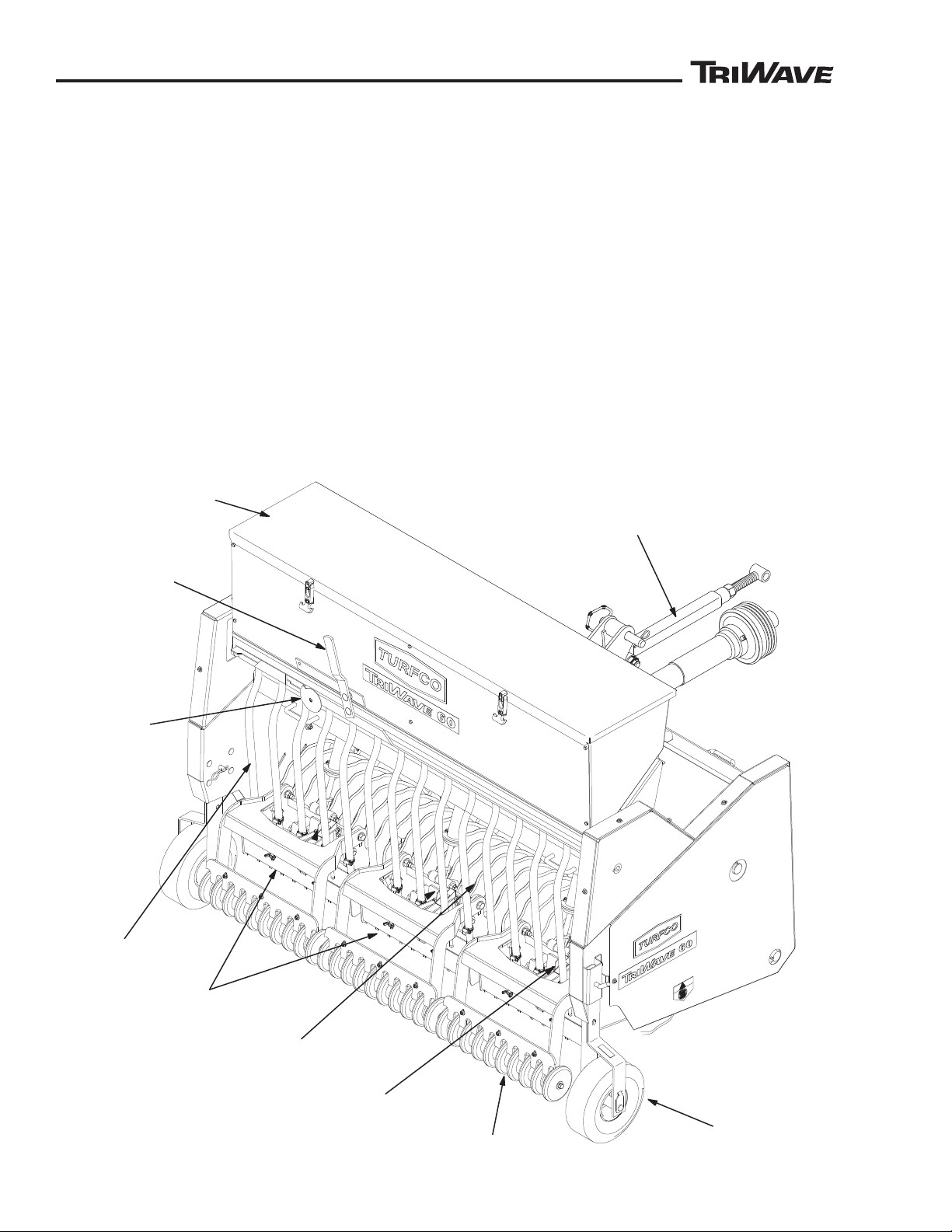
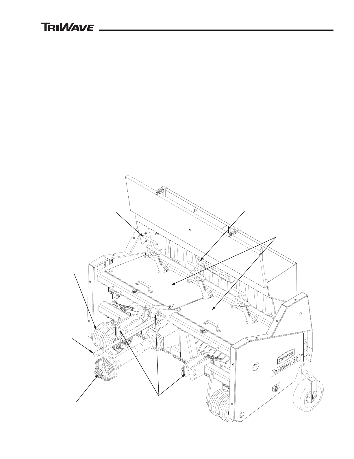
(See Figure 5 and Figure 6)
See
Figure 5 and 6 for the location of the major
components of the seeder. Do not modify the seeder in
any manner. Do not operate the seeder with damaged
or inoperable components.
Manual Tube: The manual tube is located on the front
panel of the seed box. The tube is used to store the
operators manual.
Storage Wheels: The storage wheels are designed to
protect the blades when the unit is lowered over a hard
surface or disconnected from the tractor for storage.
The storage wheels can be set in two positions, raised
and lowered. The positions are secured by pull pins.
10
85851 Rev B
Page 11
™
™
CUTTING HEAD
GUARDS
SEED BOX
DRIVE
FRONT
ROLLER
UPPER AND LOWER
THREE-POINT
HITCH POINTS
DOWN
PRESSURE
ADJUSTERS
PTO SHAFT
DS85851-02REVA
FIGURE 6
MANUAL TUBE
UPPER
LINK
TURFCO
DESCRIPTION
The wheels are not designed for transport, DO NOT
tow the seeder on the storage wheels. Tires are
equipped with a sealant. Wear eye protection when
checking tires. Check only when the valve stem is at
the top of the wheel. Inflate the tires to the pressure as
shown on the tire sidewall.
Upper and Lower Three Point Hitch Mounts: The
lower hitch mounts are equipped to accept either
a Category 1 or Category 2. The lower hole is for
Category 1, the upper hole is for Category 2.
The upper hitch point is equipped with a upper link to
attach to the tractor. The upper link can be adjusted in
length to fit different tractors. The link can be adjusted
to provide level raising and lowering of the seeder and
to allow freedom of movement for operation on uneven
ground.
PTO Shaft: The shaft connects to the tractor 540 PTO
to provide power for the seeder cutting blades. The
shaft has an operating length range of 419 mm to 600
mm (16-1/2” to 23-5/8” inches).
Cutting Head Assemblies and Blades: The seeder
is equipped with three cutting heads designed to
operate individually. The seeder has 30 round blades,
ten on each cutting head assembly. Each blade cuts
a slit in the soil for the seed. Each cutting head floats
independently from the other heads to allow it to follow
the contours of the turf. The floating helps maintain
even seed depth and ground contact.
Blade Depth Adjusters: The adjusters set the blade
depth of cut. The range is 0” inches to 1-3/8” (0 to 34.9
mm) deep. Each cutting head has its own blade depth
adjuster. The numbers on the decal are for reference
only, they do not represent any actual measured
depth.
85851 Rev B
11
Page 12

™
™
WARNING
DESCRIPTION
SAFE-14
Down Pressure Adjusters: The down pressure
adjusters provide downward force on the cutting
heads to keep the blades in the soil. The adjuster can
be adjusted to provide a light down pressure when
working in soft soil, or adjusted to provide a heavy force
to help the blades cut into hard soils. The alphabetical
letters on the decal are for reference only, they do not
represent any measured amounts of down pressure
force.
Packer Wheels: The packer wheels improve seed
contact with the soil and compress the silt cut by the
blades. There is one packer wheel for every blade.
The packer wheels are in line with the blades (slit) and
float with the cutting heads.
Seed Hopper: The hopper holds 0.135 Cubic Meter
(8251 Cubic In. Or 4.77 Cubic Ft.) or Approximately
45.35 Kg. (100 Pounds) of Grass Seed. At the bottom
of the box are rotors that evenly distribute the seed to
the seed gate.
Seed Box Front Drive Roller: The right front drive
roller provides power to the chain that drives the seed
box rotors. Power to the chain is only present when the
seeder is moving and the roller is turning. When the
seeder is raised, the front roller can be manually turned
by hand to observe (calibrate/measure) the amount
of seed being dispensed. Both the right and left front
roller are equipped with scrapers to control the buildup
of dirt and debris on the rollers. The scrapers can be
adjusted to correct for contact or wear.
Seed Gate Dial: The dial adjusts the amount of seed
flow by limiting the opening size of the seed gate. The
dial is numbered 0 thru 80, with 0 being the smallest
opening. The numbers are for reference only, they do
not indicate any seed volume or weight.
The height of the boxes is adjustable to accommodate
turf and soil conditions. If existing turf has a long length,
the boxes can be raise to avoid contact with the grass.
The grass will disrupt the even distribution of the seed
and any moisture present in the grass will transfer to
the openings in the boxes. On sites with short turf, a
lower seed box height will aid in the seed not being
blown out away from the slit by the wind before it
contacts the soil.
LOCATION AND DESCRIPTION OF THE TRIWAVE
SEEDER OPERATOR POSITION
Operator Position: The proper location for the
operator of the TriWave Seeder is seated in the tractor
seat. Always disengage the PTO drive, stop the
tractor engine and lock the brakes before leaving the
operator’s seat. Do not stand behind or allow anyone
to stand behind the seeder when it is operating. The
TriWave Blades Can Throw Objects.
TO AVOID SERIOUS INJURY,
Move To the Operator’s Position On The Tractor
Before Engaging the PTO Drive.
Always be at the operator’s position before engaging
the Tractor PTO drive.
Avoid Any Contact With the PTO Shaft. PTO Shaft
Guards Must Be Install and Operational.
Seed Gate Handle: The seed gate handle opens the
seed gate allowing flow of seed to the seed tubes
and the seed distribution boxes. When not in use, the
handle must be in the closed position to avoid seed
from emptying out of the seed hopper.
Seed Tubes: The seed tubes carry the seed from the
seed box to the seed distribution boxes. The tubes are
clear plastic to allow monitoring of the seed flow and to
monitor any buildup of moisture or debris which could
disrupt the seed flow.
Seed Distribution Boxes: The seed distribution
boxes divide the seed flow to place equal amounts
of seed in each slit. There are three boxes, one for
each cutting head. The boxes are covered with a clear
plastic window to allow monitoring of any buildup of
dirt, grass, or moisture that will slow, disrupt, or stop
the flow of seed.
12
DESCRIPTION OF THE TRACTOR OPERATOR
CONTROLS
Refer to the tractors operator manual for proper
identification and operation of the tractor controls. The
following controls are used to operate the TriWave
seeder -
Engine RPM and Gear Range Selector: Used to
control ground speed and PTO speed output.
Three Point Hitch Control: Used for raising and
lowering the TriWave seeder.
PTO Drive: Used to power the TriWave seeder.
85851 Rev B
Page 13
™
™
Operation
WARNING
WARNING
STORAGE ONLY
DO NOT USE
FOR TOWING
SAFE-08
SAFE-06
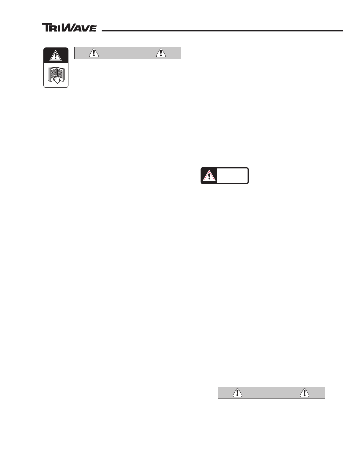
TO AVOID SERIOUS INJURY,
Read and Understand the Entire Manual
For the Seeder. Be Trained and Familiar
With the Operators Controls For the
Tractor.
Keep Hands and Feet Away From the Blades.
Move To the Operator’s Position At The Tractor
Before Engaging The PTO Drive.
Always Slowly Lower the Seeder.
Follow All Safety Precautions And Wear The
Appropriate Safety Gear.
Be Aware Of Others In The Worksite. Keep
Observers Away From The TriWave During
Operation. The TriWave Blades Can Throw
Objects.
PRE-OPERATION CHECK LIST
● Read and understand the entire manual for the
TriWave seeder and the tractor.
● Follow all safety instructions, warnings, and decals.
● Safety First – Wear the appropriate safety gear. Safety
glasses, gloves and safety shoes are recommended
when operating the TriWave Seeder.
● Check – The seed hopper. The hopper should be
clean and dry. Check the operation of the seed gate.
The gate should operate smoothly without use of
excessive force on the control handle.
● Grease – The fittings in the PTO shaft (total 2) and
drive shafts bearings (total 4).
● Inspect – The blade assemblies for damage, dirt
buildup or foreign objects.
● Check – All guards are in place, especially the PTO
shaft guards.
● Check – Retighten any loose nuts and screws to
ensure safe operation.
● Inspect and prepare the work site.
● Check – The work site for above and below ground
obstructions and/or dangerous areas.
OPERATION
Locate and mark any shallow buried natural gas,
propane gas, or other gas or fuel line that may be
damaged by the seeding process.
Locate and mark all sprinkler and irrigation heads,
above and below ground irrigation control boxes,
water shutoffs, control valves, and any shallow
buried irrigation lines that may be damaged by the
seeding process.
Locate and mark any shallow buried roof drain pipes,
drain tiling, drain catch basins, or any other buried
drainage items that may be damaged in the seeding
process.
RAISING STORAGE WHEELS
The storage wheels are designed for storage only. The
wheels keep the blades elevated during storage to
avoid damage from contact with
a hard surface. The wheels are
not meant to be used for towing
of the seeder. After the seeder has been hitched and
lifted by the tractor, the wheels must be raised onto
the “Operating” position. Pull the pin and lift into the
next higher hole. The wheels do not touch the ground
during operation. After operation, the wheels should
be returned to the lowered “Storage” position before
the seeder is lowered over a hard surface.
GROUND OPERATING SPEED
Seed application rates are based on a operating speed
of 4.8 Km/h (3 mph). Maximum operating ground speed
is 8.8 Km/h (5.5 MPH). Do not exceed the maximum
speed as poor seeding quality and excessive stress on
the machine will occur.
Choose a gear in the tractor that will provide adequate
engine speed (RPM) and proper 540 PTO speed
while staying under the 5.5 MPH maximum. During
operation, always move at the same speed to ensure
even distribution of the seed. Operating at a constant
even speed will obtain the best results.
MAXIMUM ANGLE OF OPERATION
WORK SITE PREPARATION
Inspect the work site obstructions. Plan your path
and know the location of any above ground or below
ground objects.
Under certain conditions, the TriWave Seeder blades
can reach a depth of 50 mm (1-1/2” inches). Damage
will occur to any buried object that the blades may
come in contact with.
Locate and mark all shallow buried electrical cables,
including electric service, cable TV, telephone,
outdoor lighting, any other type of buried cable that
may be damaged by the seeding process.
85851 Rev B
Do not operate the TriWave Seeder on steep slopes.
Maximum angle of operation is 15° degrees. Serious
injury can occur if operated on steep slopes or when
operated in an unsafe manner. The tractor and TriWave
seeder can tip or roll over on to the operator.
TO AVOID SERIOUS INJURY, Do Not Operate
Seeder On Slopes Over 15° Degrees. Tractor
and TriWave Seeder Can Tip or Roll Over Onto
Operator If Operated On Steep Slopes.
13
Page 14
™
™
OPERATION
0
1
2
3
4
5
6
7
8
9
10
11
12
13
14
15
16
17
0
5
10
15
20
25
30
35
40
45
50
55
60
65
70
75
80
Bentgrass
Kentucky
Bluegrass
Fescue
Ryegrass
Mixtures
5 10 15 20 25 30 35 40 45 50 55 60 65 70 75 80
Approximate Pounds of Seed Per 1000 Square Feet at 3 MPH (Kilograms of Seed Per 92.9 Square Meters at 4.8 Km/h)
Cam Gauge Dial Setting
Penncross
0.40 0.55 1.0 1.4 2.1 2.8 3.7 4.7 5.9 7.5 8.8 9.8 11.2 11.3
0.15 0.25 0.35 0.45 0.65 0.85 1.2 1.7 2.2 2.6 3.2 3.8
Type
Of Seed
Variety
50% Bluegrass
50% Fescue
50% Bluegrass
50% Rye
Tall
Perennial
Hard
Creeping
Red
0.15 0.20 0.32 0.48 0.55 0.88 1.1 1.4 1.9 2.4 3.1 3.9 4.9 5.5 5.7
0.35 0.55 1.0 1.5 2.2 2.9 3.9 4.9 6.4 7.6 8.6 9.7 9.9
0.3 0.5 0.7 1.0 1.4 1.8 2.4 3.1 3.9 4.8 5.9 6.9 7.6 7.6
0.15 0.25 0.55 0.95 1.4 2.2 3.0 4.0 5.2 6.6 8.2 9.3 10.8 12.4 12.7
Annual
0.35 0.5 0.75 1.1 1.7 2.2 3.0 3.8 4.5 5.5 6.4 7.0 6.7
Bluegrass
Rough
0.45 0.9 1.5 2.3 3.4 4.5 6.1 7.3 8.8 10.9 13.0 15.0
0.15 0.35 0.55 1.1 1.7 2.4 3.1 3.8 5.2 6.2 7.4 8.4 9.7
Bermuda
0.15 0.45 1.1 1.8 3.2 4.2 5.9 7.9 9.7 12.1 14.7 18.4
Coated
Hulled
0.25 0.65 1.4 2.2 3.2 4.1 5.4 7.1 8.3 10.9 11.8 13.7
0.5 1.3 2.2 3.4 5.0 6.7 8.9 12.5 14.9 17.5 20.9
Pounds
(Kilograms)
(0.11) (0.3) (0.64) (1.0) (1.45) (1.85) (2.45) (3.22) (3.75) (5.9) (5.35) (4.4)
(0.23) (0.59) (1.0) (1.54) (2.26) (3.04) (4.04) (5.67) (6.75) (7.94) (9.48)
Pounds
(Kilograms)
Pounds
(Kilograms)
Pounds
(Kilograms)
(0.07) (0.21) (0.5) (0.82) (1.45) (1.91) (2.68) (3.58) (4.4) (5.49) (6.67) (8.35)
(0.07) (0.16) (0.25) (0.5) (0.77) (1.09) (1.41) (1.72) (2.36) (2.81) (3.35) (3.81) (4.40)
Pounds
(Kilograms)
Pounds
(Kilograms)
Pounds
(Kilograms)
Pounds
(Kilograms)
Pounds
(Kilograms)
Pounds
(Kilograms)
Pounds
(Kilograms)
Pounds
(Kilograms)
(0.21) (0.41) (0.68) (1.05) (1.54) (2.04) (2.77) (3.31) (3.99) (4.95) (5.89) (6.80)
(0.14) (0.22) (0.31) (0.45) (0.64) (0.82) (1.09) (1.41) (1.77) (2.18) (2.67) (3.12) (3.45) (3.45)
(0.07) (0.11) (0.16) (0.21) (0.3) (0.38) (0.54) (0.77) (0.99) (1.18) (1.45) (1.72)
(0.16) (0.25) (0.45) (0.68) (1.0) (1.31) (1.77) (2.22) (2.90) (3.45) (3.90) (4.4) (4.49)
(0.18) (0.25) (0.45) (0.64) (0.95) (1.27) (1.67) (2.13) (2.67) (3.4) (4.0) (4.5) (5.08) (5.12)
(0.07) (0.11) (0.25) (0.43) (0.64) (1.0) (1.36) (1.81) (2.36) (2.99) (3.72) (4.21) (4.9) (5.62) (5.76)
(0.07) (0.09) (0.15) (0.22) (0.25) (0.40) (0.5) (0.63) (0.87) (1.09) (1.41) (1.77) (2.22) (2.5) (2.58)
(0.16) (0.22) (0.34) (0.5) (0.77) (1.0) (1.36) (1.72) (2.04) (2.50) (2.90) (3.17) (3.04)
OP85851-09REVA
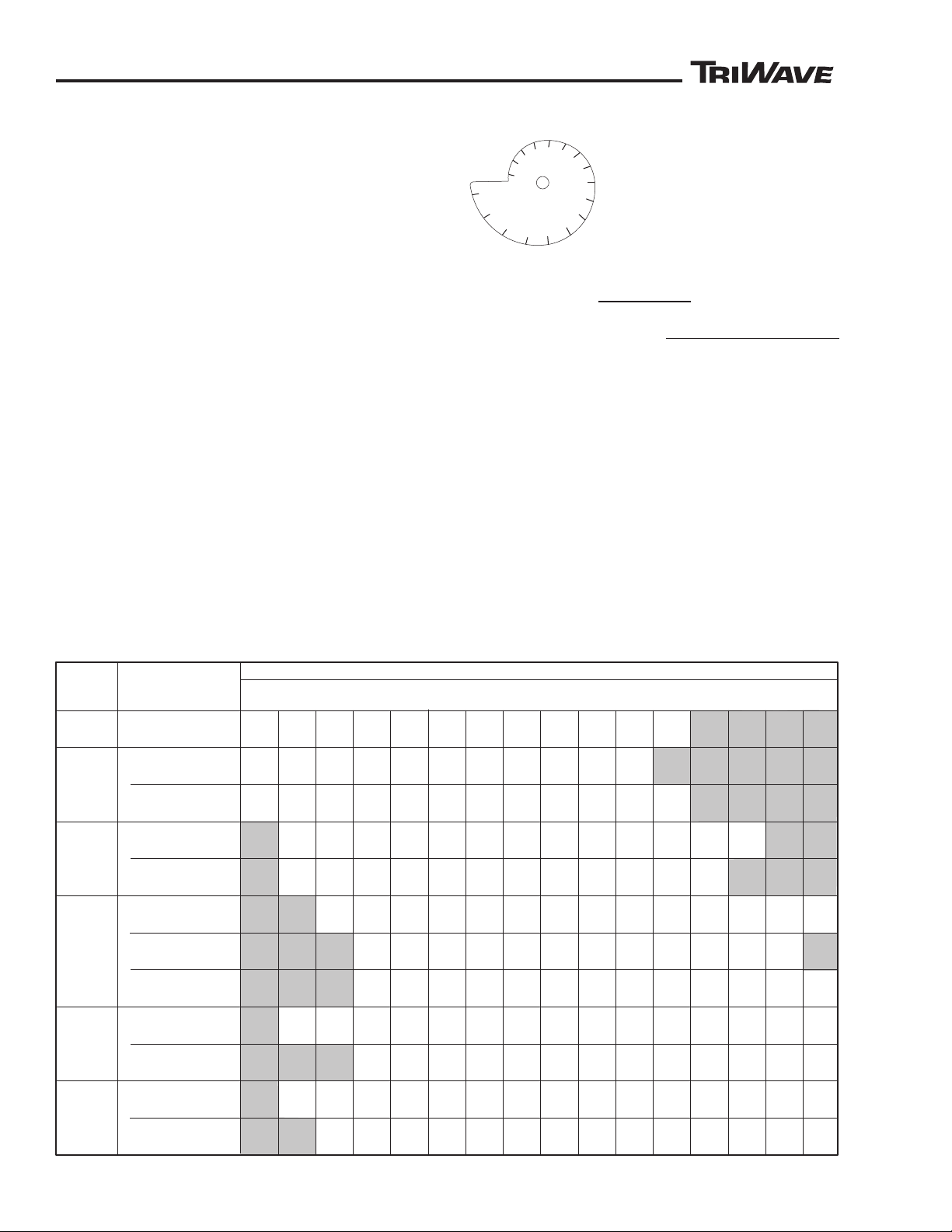
SEED APPLICATION RATE CHART
LOADING SEED HOPPER
The seed hopper has a capacity of 45.35 Kg. (100
Pounds) of grass seed. The capacity is an approximate
measure due to the differences in seed size and shape.
The hopper is divided into four connecting cambers.
Fill each chamber with equal amounts of seed. Seed
from each chamber will mix to keep seed level equal
across the chambers.
Before filling the seed hopper:
► Inspect the operation of the seed gate. With the
seed dial set at “80”, the gate should operate smoothly.
The gate should move completely from open to close
without binding.
► Check for any foreign objects inside the hopper.
► Check for any buildup of seed chaff, dust and dirt.
► Check for any moisture in the seed hopper and the
seed tubes. Clean as needed. Moisture can cause the
seed to “clump” together and cause seed flow problems.
Remove any moisture before filling the hopper.
Close the seed gate and completely fill the hopper.
Seed must be clean and dry for proper flow thru the
seed gate. Hopper is meant to be used with seed only,
do not put any fertilizers or chemicals into the hopper.
Always keep the lid closed during operation to avoid
contamination of the seed.
SETTING SEED GATE DIAL
The seed gate dial is marked
“0” thru “80”. At “0” the gate is
fully closed. The gate opening
will continue getting larger as
the setting gets closer to “80”. At
“80” the gate is fully open. Refer
to the seed application rate chart
(located on the inside of the hopper cover) for a seed
dial settings of an approximate setting to control the
rate of seed application. Because of the differences in
seed size and shape, seed application rate can vary
from the chart. Turn the dial and lock into position at
the desired setting.
For a more accurate calibration of the seed dial setting,
the front roller can be turned by hand to observe
(calibrate/measure) the amount of seed actually being
dispensed. Raise the seeder to allow the front roller
to be turned by hand. Place a plastic sheet under the
seed distribution boxes to catch the seed and turn the
roller clockwise. 92 full revolutions of the front roller
equals 1000 square feet of coverage. Weight the
amount of seed dispensed and adjust the seed dial as
needed. Also compare the amounts of seed dispensed
from each seed distribution box, all three should be
equal.
14
85851 Rev B
Page 15

™
™
OPERATING SEED GATE HANDLE
1
2
3
4
5
WARNING
25 x 25
25 x 50
50 x 50
50 x 75
75 x 75
75 x 100
100 x 100
100 x 150
150 x 150
Size of Area
To Be Seeded
In Feet
Total Area
in
Square Feet
625
1,250
2,500
3,750
5,625
7,500
10,000
15,000
22,500
8 x 8
8 x 15
15 x 15
15 x 23
23 x 23
23 x 30
30 x 30
30 x 45
45 x 45
64
120
225
345
529
690
900
1,350
2,025
Size of Area
To Be Seeded
In Meters
Total Area
in
Square Meters
Total Area
in
Square Yards
69
139
278
417
625
833
1,111
1,667
2,500
Area Conversion Chart
In Square Feet and Square Yards
Area Conversion Chart
In Square Meters
OP85851-04REVA
OPERATION
The seed gate handle, located on the rear of the
hopper, opens and closes the seed gate (located
on the bottom of the seed hopper). The handle has
only two positions, “Open” and “Close”. The range of
movement of the handle is limited by the adjustment
of the seed gate control dial. Because seed will begin
to flow as soon as the seed gate is opened, always
be prepared to move to the operators position on the
tractor and begin seeding as soon as possible. Always
close the seed gate after stopping.
The seed gate handle should move easily from open
to close, if excessive force is required to open or close
the gate, check for an obstruction in the seed gate
openings, or excess debris built up around the gate
opening and linkage.
SETTING BLADE DEPTH ADJUSTMENT
The blade depth adjustment controls the depth
of blade cut into the turf. Blade depth needs
to be adjustable to allow for the variations in
the thickness of existing turf, thatch buildup
and soil conditions. Always Stop the PTO
Drive Before Adjusting the Blade Depth
Adjustment.
TO AVOID SERIOUS INJURY,
Always Stop PTO Drive and Blades Before
Adjusting Blade Depth.
During operation, the cutting head assemblies ride
atop the existing turf on a depth plate. Only the part
of blade extending below the plate cuts the turf. The
depth of cut is controlled by how much of the blade
extends below the depth plate.
The blades must cut into the soil. The blade must cut
through any thatch to reach the soil.
Set the blade depth to cut into the soil at a planting
depth that is recommended for the seed variety being
planted. Cutting too deep can damage the existing
grass. Excessive blade depth will bury the seed
too deep. Seed buried too deep will not germinate.
Excessive blade depth will also cause undesired debris
in the slit cut by the blades.
Set the depth by loosening the adjuster locks and
moving the depth plate pointer along the scale. The
numbers on the scales are for reference only, they
do not represent any actual measured depth. A visual
measurement can be taken by measuring the distance
from the bottom edge of the blade to the bottom edge
of the depth plate finger (located between the blades)
Set all three cutting heads the same. Tighten the
locking handles firmly.
NOTE: As the blades wear the overall diameter of the
blade will become smaller. The blade depth setting will
have to be increased to compensate for blade wear
and to maintain the same depth of cut. If cutting heads
have a mix of new and used blades, the setting for
each head will vary to make up for the differences in
blade size.
85851 Rev B
15
Page 16
™
™
OPERATION
+
Kg (lbs)
A
B
C
D
E
F
G
WARNING
CAUTION
SETTING DOWN PRESSURE ADJUSTERS
The cutting heads are free floating and follow
the contour of the ground. While the weight
of the cutting heads keeps the blades in the
turf, some extra down pressure is needed to
maintain a even and constant blade depth cut.
The down pressure is adjusted by turning
the handles clockwise to increase pressure,
counterclockwise to decrease pressure.
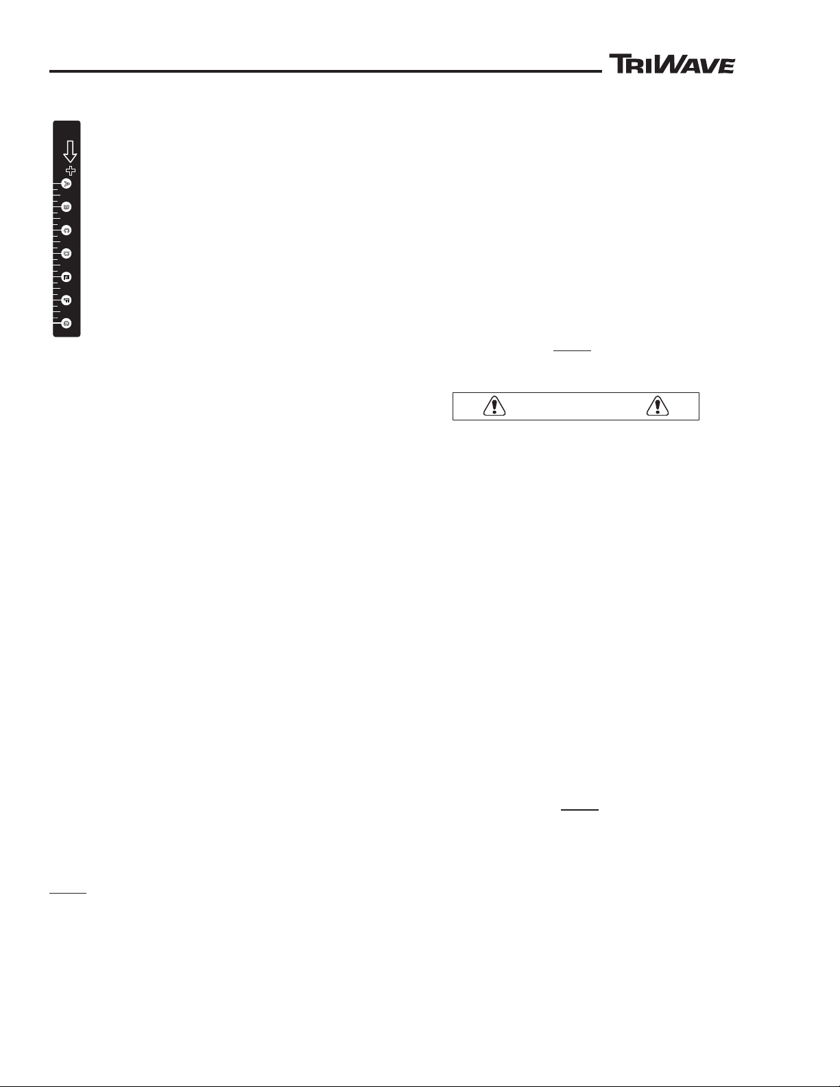
The alphabetical letters on the decal are for
reference only, they do not represent any
measured amounts of down pressure force.
Gauge the setting by using the bottom edge of
the plunger that is visible in the slot. Adjust all
three equally.
In very soft soil conditions, little or no down pressure
is needed. Added down pressure in very soft soil may
cause the cutting heads to cut too deep as a result of
being “pressed” down into the turf past the blade depth
adjustment setting.
In very hard soil, extra pressure will be needed to
maintain the depth of cut by helping to force the blade
down during the cut. In very hard soil, slowing the
ground operating speed will allow extra time for the
blade to cut and aid in the blades ability to maintaining
its depth of cut.
The following are conditions that cause the need for
down pressure adjustment changes:
● Hardness or softness of the soil
● Depth of cut
● Length of existing turf and depth of existing thatch
● Sharpness and condition of blades
● Operating ground speed
OPERATION
Plan your path. Plan to operate in straight lines. Inspect
the site, check for objects that can damage the blades
or can be damaged by the blades. Mark their location.
Check the moisture level of soil and the existing turf.
Excess moisture can cause the blades to pickup too
much soil and thatch. Excess moisture in the grass can
collect in the seed boxes and stop the flow of seed.
Step 1. Move the tractor and seeder over the turf and
slowly lower the seeder to the turf. Stop tractor engine
and set brakes.
Step 2. Review the “Setup and Installation” section
in this manual to ensure that the seeder is properly
hitched to the tractor and setup. Observe if the seed
distribution boxes contact the turf when raising and
lowering, if so adjust the upper link to correct.
16
Also check seed distribution boxes mounting height,
boxes should not touch the existing turf.
Step 3. Set the seed dial (with seed gate closed).
Step 4. Set the Blade Depth Adjusters.
Step 5. Set the Down Pressure Adjusters.
Step 6. Start tractor and lift the seeder with the tractors
three point hitch control.
Step 7. Check the PTO shaft angle - STOP, Do Not
Operate the seeder if the PTO shaft is at an angle
over 30 degrees or has overextended in length.
Step 8. Place storage wheels into the raised “Operating”
position.
Step 9. Start PTO and slowly lower seeder to turf.
TO AVOID DAMAGE TO DRIVE TRAIN
COMPONENTS,
Engage PTO Before Blades Contact The Turf.
Do Not Start Forward Movement of the Tractor
Unless the Blades are Rotating and in Contact
With the Turf.
Stop Forward Movement Before Lowering Seeder,
Do Not Raise or Lower the Seeder While In
Motion.
Step 10. Start forward movement and make short cut.
Stop forward movement, raise seeder and stop PTO.
Stop tractor engine and set brakes.
Step 11. Check the blade depth and condition of the
slit. Adjust blade depth setting and down pressure as
needed.
Step 12. Open seed box gate. NOTE: A small amount
of seed will initially flow through the seed tubes when
the gate is first opened. A steady flow of seed will only
occur when the seed gate is open and the front roller
is turning.
Step 13. Set tractors engine speed and select proper
gear range. DO NOT EXCEED 5.5 MPH.
Step 14. Start PTO and slowly lower seeder to turf.
Step 15. Start forward movement. Operate in a straight
line only. Avoid turns with blades in ground. Make vary
gentle curves only. Turns made with the blades in the
ground will cause the seed distribution boxes and
packer wheels to be out-of-line with the slit and cause
undue stress to the cutting heads and drives.
Observe if upper link is becoming tight and lifting
the seeder blades out of ground when operating on
uneven ground.
85851 Rev B
Page 17
™
™
OPERATION
TriWave™ 60” Seeder
Product Number 85851
Patent Pending
521.6 Kg (1150 lbs)
8.8 Km\h
MAX
(5.5 mph)
STORAGE ONLY
DO NOT USE
FOR TOWING
FIGURE 7
OP85851-07REVA
A
B
C
D
E
F
G
H
I
+
Kg (lbs)
A
B
C
D
E
F
G
1
2
3
4
5
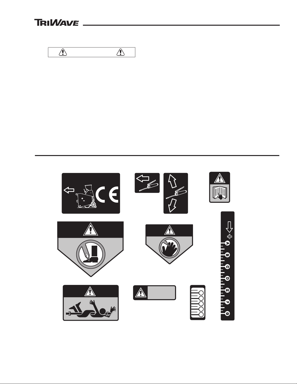
A. Product Identification Decal
B. Grease Fitting Location Decal (Qty 6)
C. Read Manual Warning Decal
D. Foot Hazard Warning Decal
E. Hand Hazard Warning Decal
F. Pto Shaft Hazard Warning Decal
G. Storage Wheel Warning Decal
H. Depth Of Cut Adjustment Decal
I. Down Pressure Adjuster Decal
WARNING
CAUTION
Step 16. At end of the row, stop forward movement, lift
the seeder and stop the PTO.
TO AVOID DAMAGE TO DRIVE TRAIN
COMPONENTS,
Do Not Drive Forward With Blades In the Ground
and PTO Off.
Step 17. Make your turn for the next pass. Ensure
that the seeder is lifted high enough for the blades
and packer wheels to clear the turf. Avoid dragging the
packer wheels and blades on the turf during turns.
Step 19. For even slit spacing between passes, use an
outside edge of the front roller to gauge the next slit, it
is approximately in line with the outside blade.
Step 20. Restart the PTO, lower to the turf and begin
forward movement.
Step 21. Cross cut if desired.
Decals
IN OPERATION QUALITY CHECKS
During operation, stop and check the quality of your
seeding. Stop the PTO drive, close the seed gate, and
check the following:
● Check the depth of cut and the condition of the slit
● Check seed flow and seed dial setting.
● Check seed levels in hoppers. Note an uneven level
between chambers (This is an indication that one
side is dispensing more seed than the other).
● Check that seed is dropping in the slit.
● Check that the packer wheels are in line with the slit
and pressing the seed down for soil contact.
● Check for thatch or debris build up around the blades
and seeder frame components.
● Check for build up of thatch, dirt or debris plugging
seed flow in seed distribution boxes.
Correct any problems to ensure safe operation and
even seed distribution.
85851 Rev B
17
Page 18

™
™
OPERATION
WARNING
Operator Daily Inspection
TO AVOID SERIOUS INJURY,
Do Not Attempt To Perform Any
Inspection, Adjustment, or Service
Procedure With Any Part of the
TriWave Seeder Operating.
STOP ALL POWER TO THE PTO SHAFT.
Work Safely and Wear the Appropriate Safety
Gear When Inspecting, Servicing or Making
Adjustments.
Follow All Safety Hazard Warnings and Decals.
Before each use, check the following items. Refer any
repairs to service personnel.
● Inspect for damaged, inoperable, or missing
components or missing guards. Do not operate
any machine with missing, inoperable, damaged
components or guards.
● The seeder operates with vibration. Before and
after each use, check and retighten any loose nuts
and bolts.
Storage
TO STORE THE TRIWAVE SEEDER OVER A
EXTENDED PERIOD, perform a complete inspection.
Refer any needed service or repair to service level
personnel. Clean and dry the hopper, seed tubes and
seed distribution boxes. Remove any remaining seed
and any moisture. Use low pressure wash on the seeder,
DO NOT use high pressure wash, high pressure wash
can force water onto the bearings and chains. Perform
a complete lubrication procedure. Apply a film of light
machine oil to the blades and chains to control rust.
Store the seeder out of direct sunlight.
TO RETURN TO SERVICE AFTER EXTENDED
STORAGE, inspect the entire machine for any damage
that may have occurred during storage. Locate and
inspect all hitch pins, covers, guards, and the PTO
shaft. Inspect the inside of the seed hopper. Remove
any foreign objects and clean as needed. Refer any
needed service or repair to service level personnel.
● Inspect all controls for proper operation. Do not
operate any machine with missing, inoperative or
damaged controls.
● Check condition of the blades.
● Check for a buildup of dirt or debris on the machine.
Clean the machine after each use. Do not highpressure wash.
● Check the inside of the seed hopper. Hopper
should be clean and dry. Look for debris caught in
seed gate holes. Seed gate should operate without
excessive force needed to move handle.
● Check the storage wheels for proper tires for
inflation. If needed, inflate to the pressure shown
on the tire. Tires are equipped with a sealant.
Wear eye protection when checking tires. Check
only when the valve stem is at the top of the wheel.
Inflate the tires to the pressure as shown on the
tire sidewall.
● Check for proper lubrication of the entire machine.
Maintain proper lubrication intervals.
● Visually check for oil leaks on the right angle
gear box. If leaks are detected, check the gear oil
level in the box (with box setting level). Refill as
needed.
18
85851 Rev B
Page 19
™
™
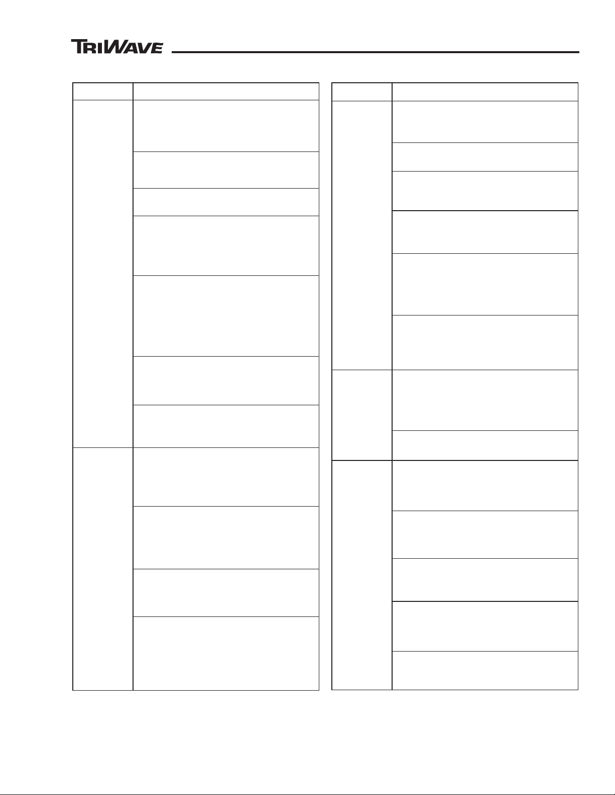
Troubleshooting Table
OPERATION
PROBLEM POSSIBLE CAUSE
Seed Not
Dispensing
Or Flowing
Unevenly
Check Operating Ground Speed Maximum Ground Speed Is 5.5 MPH
(8.8 km/h). Check Engine Speed/PT
Speed and Gear Selection.
Check for Moisture In the Seed Hopper,
Seed Tubes, and Seed Distribution
Boxes.
Check for Grass, Dirt or Debris in the
Seed Distribution Boxes.
Check Height of Seed Distribution
Boxes. Boxes Set
Too Low Will Collect
Moisture or Dirt and Restrict Seed Flow.
Boxes Set Too High Will Allow Seed To
Miss Dropping In Slit.
Ensure That Right Front Roller Is
Turning During Operation. Roller Must
Contact the Ground and Turn During
Operating. Front Roller Drives the Seed
Hopper
. Check Tractor Draft Control
Not Allowing Seeder To Ride Along Turf.
Set Draft Control To Off.
Ensure The Seed Gate Is Opening.
Seeds Dropping Thru Seed Tubes
Should Be Visible When the Seed Gate
Is Opened.
Check Seed Gate Dial Setting.
of a Setting May Restrict Larger Sized
Seed.
Seed Not
Dropping In
Slit
Check Height and Level of Seed
Distribution Boxes. Boxes Set
Will Allow Seed To Miss Dropping In
Slit. Boxes Set Unlevel Will Cause Seed
To Collect To One Side.
Check Three-Point Hitch. Seeder Must
Pull Straight During Operation, Uneven
Hitch Will Cause Seed Distribution
Boxes
To Miss the Slit When Dropping
Seed.
Tractor Sway Bar Linkage Not Installed
or Adjusted Properly. Seeder Swinging
Side to Side During Operation. Set
Sway Bars.
Storage Wheels In Lowered “Storage”
Position Causing Rear of Seeder
Sit Too High During Operation. Wheels
Should Not Touch the Ground During
Operation. Raise Wheels and Lock Into
“Operating” Position.
O
To Low
Too High
To
PROBLEM POSSIBLE CAUSE
Blades Not
Cutting Into
Soil
Down Pressure
Soil Condition. Increase Pressure In
Harder Soil.
Adjusters Not Set For
All Blade Depth Adjusters Not Set Equal
or Not Set To Proper Depth.
Operating Ground Speed Too Fast.
Blade Not Allowed Enough Time To Cut
Soil. Adjust Speed.
Excessive Blade Wear. Diameter Of
Blades Worn Smaller Than Adjustment
Range of Depth Setting Adjusters.
Storage Wheels In the Lowered
“Storage” Position. Wheels Should Not
T
ouch the Ground During Operation.
Raise Wheels and Lock Into “Operating”
Position.
No Slack In Upper Link of Three Point
Hitch. Tractor Picking Up the Seeder
(Blades Lifting Out of the Turf) On
Uneven Ground. Adjust Upper Link.
Blades
Cutting
Deep
Down Pressure Adjusters Not Set
Too
For Soil Condition. Too Much Down
Pressure Will Force Blades Deeper
Than Desired. Decrease Pressure In
Softer Soil.
Blade Depth Adjusters Not Set Equal or
Not Set To Proper Depth.
Excessive
Noise or
ibration
V
Check All Bearings of Proper
Lubrication. Refer To Lubrication
Section In This Manual. Check for
Excessive Wear.
Check Lubrication Level In Right Angle
Gear Box. Refer To Lubrication Section
In This Manual. Check for Excessive
Wear.
Check All Chains For Proper Tension or
Excessive Wear. Check Idler Sprockets
For Proper Lubrication.
Check all Chain Sprockets For
Alignment. Check For Chains Rubbing
or Contacting Frame Sides, Hardware,
or Guards.
Check For Debris, Foreign Objects or
Grass Buildup On Blades or Caught On
Rotating Shafts
85851 Rev B
19
Page 20
™
™
SERVICE
RAISE
PACKER
WHEELS
REMOVE
CLEAR
PLASTIC
PANEL
ADJUST CLEARANCE WITH GRASS
ADJUSTING
SLOTS
SV85851-03REVA
FIGURE 8
SEED DISTRIBUTION BOX
MOUNTING
SCREWS
MOUNTING
SCREWS
TURFCO
TURFCO
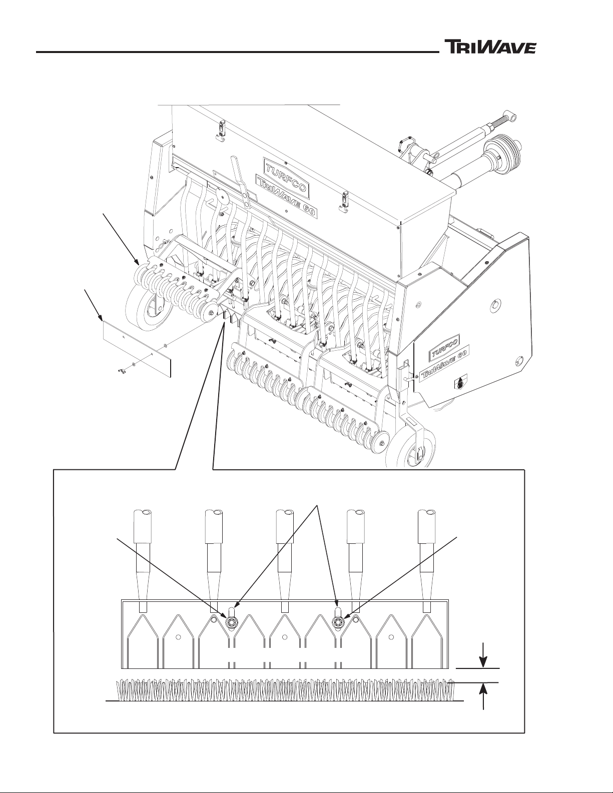
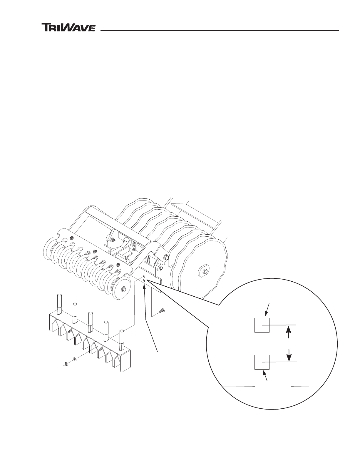
Seed Distribution Box Height Adjustment
(See Figure 8 and Figure 9)
20
85851 Rev B
Page 21
™
™
SERVICE
UPPER AND LOWER
SEED
DISTRIBUTION BOX
MOUNTING HOLES
SV85851-04REVA
FIGURE 9
UPPER
MOUNTING HOLE
LOWER
MOUNTING
HOLE
22.2 mm (7/8”)
NOTE:
AFTER ADJUSTING SEED BOX
HEIGHTS, OBSERVE IF THE
BOXES CONTACT THE GROUND
WHEN RAISING OR LOWERING
THE SEEDER. IF CONTACT IS
NOTED, READJUSTMENT THE
THREE POINT HITCH TOP LINK
WILL BE REQUIRED (ADJUST
SHORTER).
The seed distribution boxes should not touch the turf. If
the boxes contact the turf during operation, dirt, debris,
thatch and moisture can buildup in the openings of the
boxes and restrict or plug the flow of seed.
The height of the boxes can be adjusted. Ideal spacing
between the boxes and the turf is approximately 12
mm (1/2”). The variations on operating settings that
will require resetting the box height are -
● Depth of cut setting
● Down pressure adjusters
● Softness of the turf
● Length of existing grass (turf)
● Wetness of grass or soil
● Seed not falling in slit cut by blade
● Setting of upper link on the three point hitch.
● Boxes touching the turf when raising or lowering
the seeder.
To adjust the height -
Step 1. Removing the clear plastic covers.
Step 2. Loosening the mounting screws.
Step 3. Raise or lower the boxes. The box has a up
and down range of 24 mm (1” inch). An additional
22.2 mm (7/8”) of height adjustment can be gained
by removing the boxes and remounting the screws
in the upper mounting hole (See Figure 9).
Step 4. Check that the box is level and tighten mounting
screws.
Step 5. Replace the plastic covers.
After adjustment, check the boxes to ensure that they
are all set at the same height and are level and straight.
Clean the boxes as needed.
85851 Rev B
21
Page 22
™
™
WARNING
SERVICE
GREASE
PTO SHAFT (2 PLACES)
GREASE
RIGHT AND LEFT
HAND
DRIVE SHAFT
BEARINGS
(4 PLACES)
RIGHT ANGLE
GEAR BOX
(GL90 GEAR LUBE)
SV85851-01REVA
FIGURE 10
FILLER PLUG
AND VENT
DRAIN
PLUG
OIL LEVEL
PLUG
OIL FILL
LEVEL
EUROPEAN LUBRICANTS, FUEL,
AND PARTS DISPOSAL NUMBERS
Gear Oil ............ 54112
Grease.............. 54202
Plastic Parts ..... 57127
Tires.................. 57502
TO AVOID SERIOUS INJURY,
Do Not Lubricate the Seeder When It Is
Operating. All of the Following Lubrication
Fittings Involve or Are Near Rotating Parts
and Moving Parts.
Always Follow All Safety Precautions and
Wear the Appropriate Safety Gear.
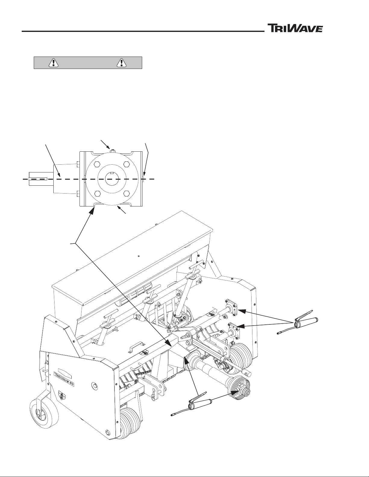
Lubrication
(See Figure 10)
GREASE FITTINGS: After Every 4 Hours of Operation –
● PTO Shaft (2 places)
● Drive Shaft Bearings (4 Places)
RIGHT ANGLE GEAR BOX: Maintain oil level with 90 weight
gear lube (GL90). Fill to level shown on Figure 10 (even with
the oil level plug on the side of the gear box). Change oil
after 500 hours of operation. Keep vent on filler plug clean.
CHAINS: The chains are sealed and require no further
lubrication. However, protect the drive chains from rust and
moisture with a very light coating of oil. The chain sprockets
should be cleaned of any dirt build-up to ensure proper chain
contact. Do not over oil, excess oil will attract and collect
dust and dirt.
DO NOT HIGH PRESSURE WASH. High pressure washing
can force water into the sealed bearings washing away the
lubrication. Periodically clean the entire machine of dirt,
grease and grass build-up and lubricate all pivot points with
light oil.
22
85851 Rev B
Page 23
™
™
STORAGE WHEEL TIRE AIR PRESSURE: Check
SV85851-02REVA
RIGHT SIDE CHAINS
LEFT SIDE CHAIN
LEFT SIDE DRIVE
CHAIN IDLER
SPROCKET
RIGHT SIDE DRIVE
CHAIN IDLER
SPROCKET
FIGURE 11
12.5 mm
(1/2”)
MAX.
12.5 mm
(1/2”) MAX.
CHAIN MUST NOT
CONTACT FRAME
OUTSIDE
SEED BOX
DRIVE CHAIN
IDLER
SPROCKET
12.5 mm
(1/2”)
MAX.
INSIDE
SEED BOX
DRIVE CHAIN
IDLER
SPROCKET
air pressure in the storage wheels (tires) before and
after each use. The tires are equipped with a sealant.
To avoid leakage of sealant, check pressure or correct
pressure only when the valve stem is at the top of the
wheel. WEAR EYE PROTECTION.
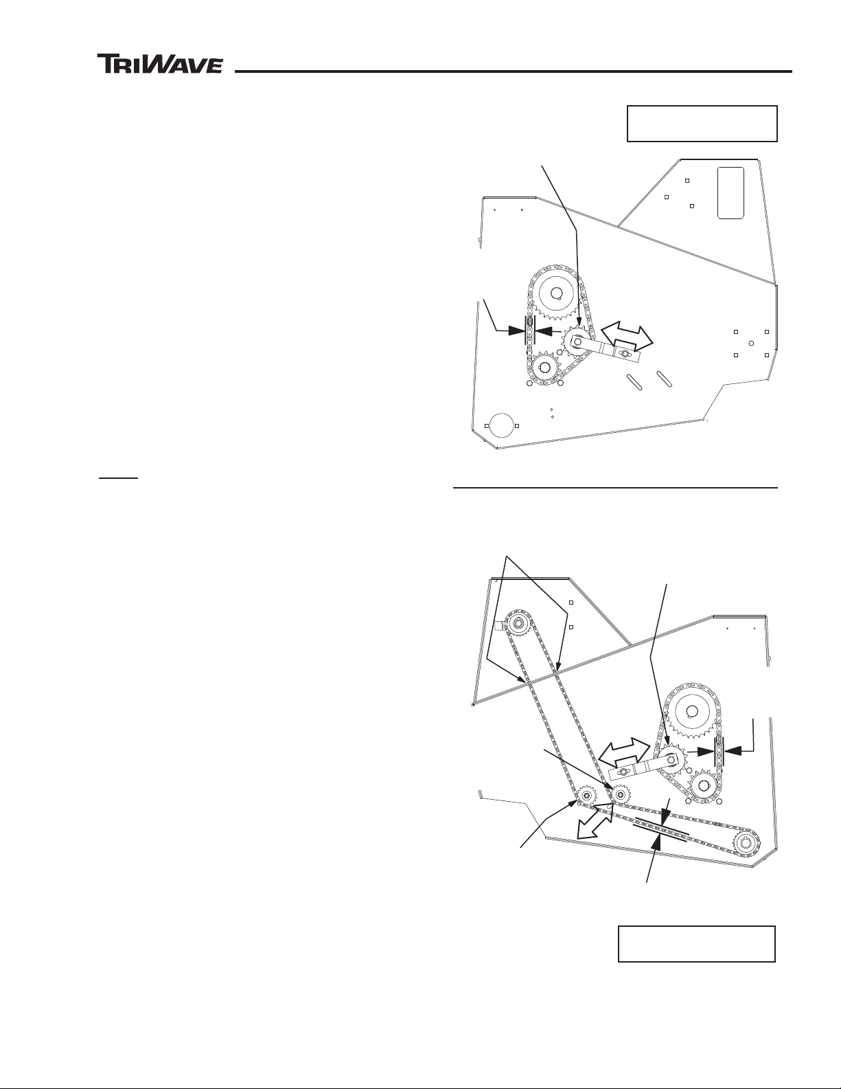
RIGHT AND LEFT DRIVE CHAIN TENSION
ADJUSTMENT (See Figure 11)
The drive chains transfer power from the upper drive
shafts to the lower cutter head drive jackshafts. The
tension on both chains must be adjusted equal.
Unequal tension will cause stress to the chains and
drive components. Excess slack in the chain should
be removed to avoid skipping of the chain over the
sprockets and uneven power distribution.
If the jackshafts or jackshaft sprockets (lower shafts)
have been removed for repair or if the position of the
bearings that hold the jackshafts to the frame have
been disturbed, the jackshaft will require realignment
before the drive chain tension adjustment can be set.
See “Jackshaft Alignment Procedures” on page 26 of
this manual for instructions.
Chain Adjustment
SERVICE
● Before adjusting, clean the chain and sprockets to
ensure proper chain and sprocket contact.
● Loosen both the right and left side drive chain idler
sprockets and move them along the slot in the frame
to reach the chain tension (movement) side to side
a maximum of 12.5 mm (1/2” inch). Take the tension
measurement on the chain half way between upper
and lower drive shaft sprockets.
SEEDER BOX DRIVE CHAIN ADJUSTMENT (See
Figure 11)
The seeder box is chain driven by the right side front
roller. Excess slack in the chain should be removed to
avoid skipping of the chain over the sprockets. Skipping
will cause wear and uneven seed distribution.
● Before adjusting, clean the chain and sprockets to
ensure proper chain and sprocket contact.
● Loosen the inside idler and move along the slot in
the frame to reach chain tension (movement) up
and down a maximum of 12.5 mm (1/2” inch). Take
the tension measurement on the chain half way
between the front roller sprocket and the inside idler
sprocket.
● If needed, additional chain tension adjustment can
be made by moving the outside idler sprocket.
● Check the chain where it passes thru the hole to the
upper part of the frame, the chain must not touch
the frame.
85851 Rev B
23
Page 24
™
™
SERVICE
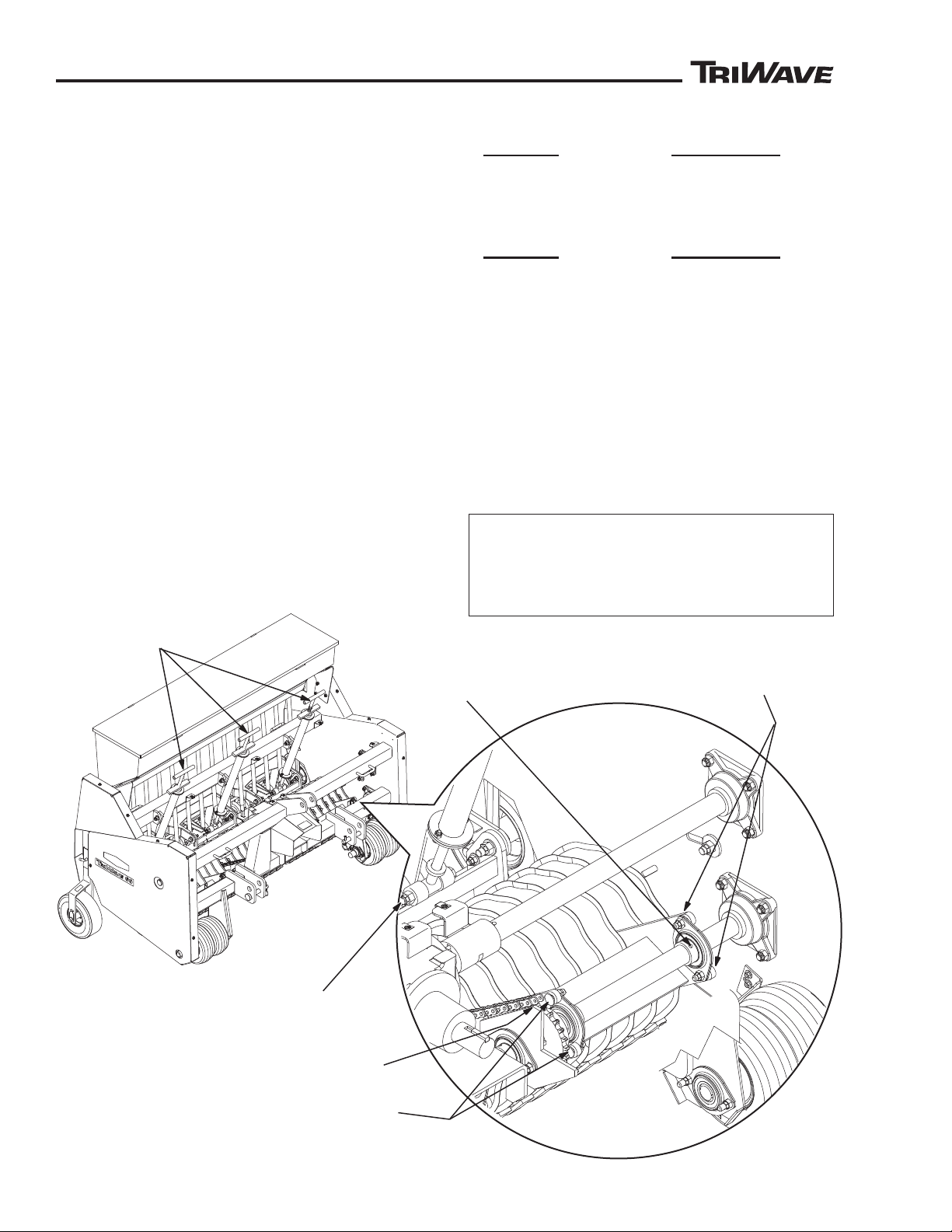
DOWN
PRESSURE
ADJUSTERS
DO NOT
LOOSEN
SET SCREWS
REMOVE HARDWARE HOLDING
CUTTER FRAME TO BEARING
REMOVE MASTER LINK FROM CHAIN
REMOVE HARDWARE HOLDING
DOWN PRESSURE ADJUSTER
TO CUTTING HEAD
REMOVE HARDWARE HOLDING
CUTTER FRAME TO BEARING
FIGURE 12
SV85851-06REVA
Cutting Head Removal and Blade Replacement
Use The Following Steps To Remove The Cutting
Heads For Installation Of Individual Blades or Entire
Blade Assemblies.
REMOVING CUTTING HEAD (See Figure 12)
Step 1. Place plywood on floor under the cutting head
to protect the blades. Place storage wheels in down
position and set seeder down.
Step 2. Remove both top covers.
Step 3. Remove the lower ends of the seed tubes
from the seed distribution box on cutting head being
removed.
Step 4. Remove the master link from the chain that drives
the cutting head being removed. Remove chain.
Step 5. Remove the down pressure on cutting head
being removed. Turn adjuster out until all pressure is
removed.
Step 6. Disconnect the cutting head frame from the
bearings by removing the hardware (4 places). DO
NOT change or move the location of the bearings. Do
not loosen the bearing set screws.
WARNING - Cutting head will drop down when
hardware is removed.
Step 7. Remove the hardware holding lower end of
the down pressure adjuster to the cutting head being
removed.
WARNING - Cutting head will drop down when
hardware is removed.
Step 8. Roll the cutting head assembly out of the back
of the seeder.
REMOVING AND REPLACING BLADE ASSEMBLY
AND/OR REPLACING INDIVIDUAL BLADES
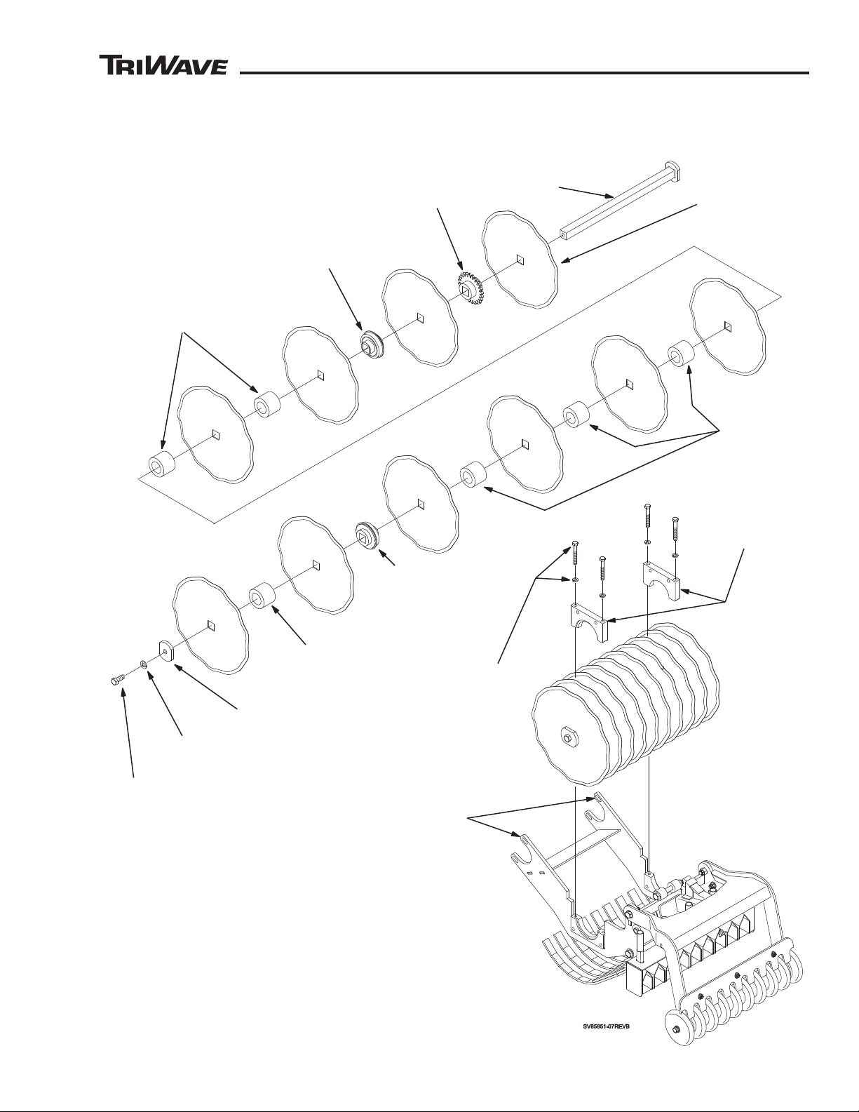
(See Figure 13 and Figure 14)
Step 9. Remove the four screws holding top caps to
cutting head frame. Remove top caps - note position
of caps, do not mix sides or positions.
Step 10. Lift blade assembly from cutting head frame
CONTINUE TO STEP 11 IF REPLACING
INDIVIDUAL BLADES.
SKIP TO STEP 14 IF INSTALLING A COMPLETE
BLADE SHAFT ASSEMBLY .
24
85851 Rev B
Page 25
™
™
Step 11. Disassemble shaft by removing hex head
BLADE
AXLE
BLADES
(NUMBERED 1
THRU 10)
SPROCKET
BEARING
(SNAP RING FACING
TOWARDS BLADE #2)
PLASTIC
SPACERS
PLASTIC
SPACERS
PLASTIC
SPACER
END CAP
PLATE
LOCK
WASHER
HEX HEAD
SCREW
(SEE NOTE C)
HEX HEAD
SCREW
AND LOCK
WASHER
(SEE NOTE B)
NOTE A: Do Not Mix Or Exchange Caps From One Side
To Other Side Or To Other Cutting Head Assemblies.
Caps are matched with Bottoms.
NOTE B: Torque Screws To 180 To 200 Inch Pounds
(15 to 16.7 ft/lbs - 20.3 to 22.6 newton meters)
#1
#2
#3
#4
#5
#6
#7
#8
#9
#10
BEARING
TOP CAP
(SEE NOTE A)
BEARING
(SNAP RING
FACING
TOWARDS
BLADE #9)
FIGURE 13
NOTE C: Use LOCTITE® On Screw Threads
Torque Screws To 50 - 60 Foot Pound (67.8 - 81.3 Nm)
USE SLOTS TO
ADJUST CHAIN TENSION
WHEN REINSTALLING
screw on end, Remove blades, spacers, bearings
and sprockets.
SERVICE
85851 Rev B
25
Page 26
™
™
SERVICE
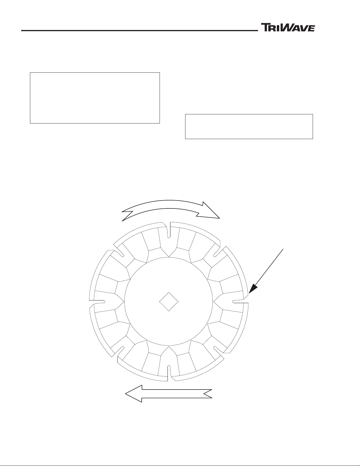
BLADE ROTATION
DIRECTION OF TRAVEL
FRONT OF MACHINE
DIRECTION
OF TRAVEL
FRONT OF MACHINE
ROTATION
45° CUT IN NOTCH
SV85851-15REVB
FIGURE 14
Step 12. Reassemble parts in order shown in Figure 13.
Note: Bearings must face as shown in Figure 13 with
snap rings facing blade #2 and blade #9.
Notched Blades are Directional and must be
installed in the proper rotational direction .
See Figure 14
Notches do not need to be indexed or
staggered from blade to blade.
Step 13. Secure assembly with hex head screw, lock
washer and end cap. Use loctite on screw. See Note C
for torque setting.
Step 14. Place blade shaft assembly back into cutter
head frame. Snap rings on bearings must fit into
grooves on cutting head.
Step 15. Replace top caps. Top caps must be
replaced in their original location with snap ring
groove positioned to match the cutting head.
Step 16. Replace hardware in top caps and torque to
180 to 200 inch pounds.
Step 17. Reinstall cutting head unit to seeder.
Make sure chain is in line with sprocket. Reinstall
pin for down pressure spring.
Adjust cutting head chain tension by moving
cutting head in slots where the bearing attach
(See Figure 13).
Step 18. Replace both top covers.
26
85851 Rev B
Page 27
™
™
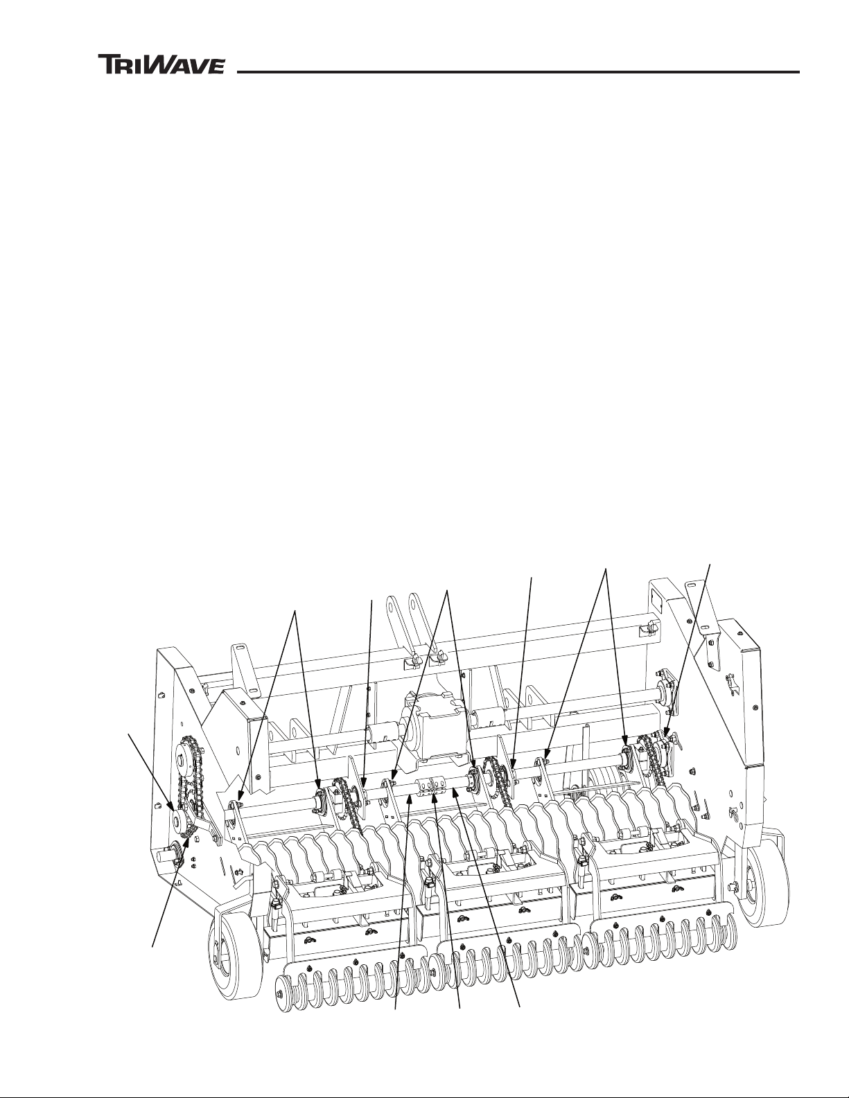
SV85851-08REVA
[F]
[D]
[F]
[E]
Both Sides
[A]
[G]
Both Sides
FIGURE 15
[C]
[C]
[C]
[A]
[B]
Both
Sides
Cutter Head Jackshaft Alignment
SERVICE
JACKSHAFT ALIGNMENT PROCEDURES
(See Figure 15)
If the jackshafts [A] or the outer jackshaft sprockets [B]
have been removed for service, or if the location of any
of the bearings [E] [F] (total 4) holding the jackshafts
to the frame have been disturbed, the jackshafts will
need to be realigned. Use the following steps to realign
the shafts -
Step 1. Remove the down pressure on all three cutting
heads. Turn down pressure adjusters out until all
pressure is removed. Cutting heads assemblies
should not apply any pressure to the jackshafts.
Step 2. Loosen (but do not remove) all of the screws
that hold the cutting head bearings [C] to the shaft.
DO NOT LOOSEN SET SCREWS. Slide cutting
head forward to remove any tension on the cutting
head chains. Chains should not apply any pressure
to the jackshafts.
Step 3. Loosen all the jackshaft collar set screws [D].
Step 4. Loosen (but do not remove) the screws holding
the two outside jackshaft bearings [E] and the two
inside jackshaft bearings [F] to the frame. DO NOT
LOOSEN SET SCREWS
Step 5. Retighten the set screws in the jackshaft collar
[D].
6. Retighten the screws holding the two outside
Step
bearings [E] to the frame.
Step 7. Retighten the screws holding the two inside
bearings [F] to the frame.
Step 8. Loosen the set screws in the jackshaft collar
[D].
Step 9. Set the two outside drive chains [G] according
to the instructions in the chain adjustment section of
this manual.
Step 10. Retighten the set screws in the jackshaft
collar [D].
Step 11. Readjust the chain tension on the cutting
head chains and retighten the hardware for the
cutting head bearings [C] (correct chain tension for
the cutting head chains is 1/4” movement up and
down).
85851 Rev B
27
Page 28
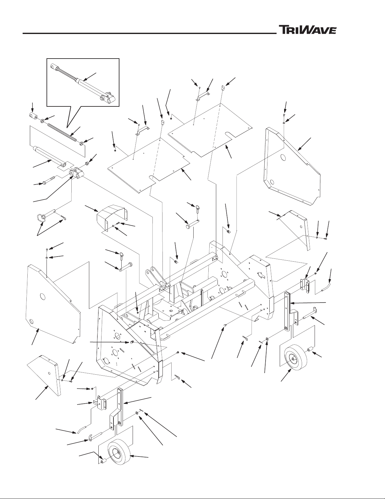
PARTS LISTS
™
™
1
1
2
7
3
4
3
2
4
5
6
5
6
7
8
8
9
9
10
1
1
11
13
12
15
14
15
14
15
14
15
16
17
18
20
19
20
21
21
22
22
23
24
23
24
31
29
30
28
27
33
35
34
35
34
32
PL85851-08REVA
36
15
14
24
14
31
26
25
37
Guards, Shields and Storage Wheels
28
85851 Rev B
Page 29

PARTS LISTS
™
™
Guards, Shields and Storage Wheels
Item Part Description Qty.
No. No.
1 664402 Wheel Caster .......................................................................................... 2
2 661300 Wheel and Tire Assembly ........................................................................ 2
3 664401 Spacer ..................................................................................................... 2
4 664406 Axle, Caster Wheel ................................................................................. 2
5 660836 Washer, Flat, 49/64” ID x 1-5/16” OD x 3/32” Thick ................................ 2
6 460052 Pin, Cotter, 3/16” x 1” .............................................................................. 2
7 664409 Gauge, Wheel .........................................................................................2
8 664419 Pin, Wheel Retainer ................................................................................2
9 660076 Pin, Hair, .148 Wire x 2-3/4” Long ........................................................... 2
10 657766 Bolt, Carriage, 3/8”-16 x 3/4” ................................................................... 8
11 444810 Nut, Hex, 3/8”-16 Nylock ......................................................................... 8
12 664543 Cover, Upper Side Panel, Right Hand ..................................................... 1
13 664548 Cover, Upper Side Panel, Left Hand ....................................................... 1
14 453023 Washer, Flat, 9/32” ID x 5/8” OD x 1/16” Thick ..................................... 24
15 400108 Screw, Hex Head, 1/4”-20 x 3/4” ........................................................... 24
16 664418 Cover, Side, Left Hand ............................................................................ 1
17 664415 Cover, Side, Right Hand .......................................................................... 1
18 664549 Panel, Front Cover, Right Hand .............................................................. 1
19 664551 Panel, Front Cover, Left Hand ................................................................. 1
20 662620 Nut, 1/4”-20 U-Type ................................................................................. 8
21 663971 Screw, T-Handle Knob, 1/4”-20 ...............................................................8
22 664550 Handle, Cover .........................................................................................2
23 658224 Bolt, Carriage, 1/4”-20 x 1/2” ................................................................... 4
24 444830 Nut, Hex, 1/4”-20 Nylock ......................................................................... 8
25 665217 Upper Link Assembly, Includes Items 26 Thru 32 ................................... 1
26 665210 Pivot, Upper Link ..................................................................................... 1
27 665215 Tube, Upper Link .....................................................................................1
28 665224 Screw, Hex Head, 3/4”-10 x 5” ................................................................ 1
29 664299 Nut, Hex, 3/4”-10 Nylock ......................................................................... 1
30 665214 Rod, Upper Link ......................................................................................1
31 665296 Nut, Hex, 7/8”-14 ..................................................................................... 1
32 665294 Rod End, Round ......................................................................................1
33 661727 Pin, Hitch, Includes Hair Pin Cotter ......................................................... 1
34 664618 Pin, Lower Link Arm ................................................................................ 2
35 658297 Pin, Lynch ............................................................................................... 2
36 664835 Guard, PTO Shaft ................................................................................... 1
37 499410 Nut, Clip, 1/4”-20 ................................................................................... 20
85851 Rev B
29
Page 30
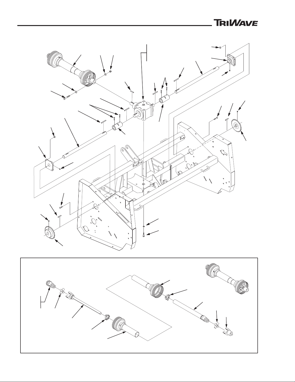
PARTS LISTS
™
™
7
1
28
29
2
2
3
3
4
4
5
5
6
6
7
8
8
9
9
10
10
1
1
11
12
12
13
14
15
TRACTOR
END
PTO SHAFT SERVICE PARTS
5
5
PL85851-02REVA
6
24
27
26
19
22
27
23
25
22
SEEDER
END
20
21
18
17
17
16
PTO, Gearbox and Drive Shafts
30
85851 Rev B
Page 31
PARTS LISTS
™
™
PTO, Gearbox and Drive Shafts
Item Part Description Qty.
No. No.
1 664413 Gearbox, Right Angle .............................................................................. 1
2 664397 Coupling, Includes Screws ...................................................................... 2
3 ------ Screw, Socket Head, 1/4”-28 x 5/8” ........................................................8
4 664389 Shaft, Drive ............................................................................................. 2
5 499166 Key, Square, 5/16” x 1-3/4” ..................................................................... 4
6 657852 Key, Square, 5/16” x 1-1/4” ..................................................................... 3
7 664398 Bearing .................................................................................................... 2
8 415561 Screw, Set, 5/16”-24 x 5/16” .................................................................... 4
9 400374 Screw, Hex Head, 7/16”-20 x 1-1/2” ........................................................8
10 444832 Nut, Hex, 7/16”-20 Nylock ....................................................................... 8
11 664394 Sprocket, 60B25 ...................................................................................... 2
12 415553 Screw, Set, 5/16”-18 x 5/16” .................................................................... 4
13 400404 Screw, Hex Head, 1/2”-13 x 1” ................................................................ 4
14
446154 Washer, Lock, 1/2” .................................................................................. 4
15 665197 PTO Drive Shaft, 35R Universal Joint Telescoping ................................. 1
16 400454 Screw, Hex Head, 1/2”-20 x 3-1/2” ..........................................................1
17 452010 Washer, Flat, 1/2” ID x 1-1/4” OD x 5/64” Thick ...................................... 2
18 444816 Nut, Hex, 1/2”-20 Nylock ......................................................................... 1
Service Parts
For 665197
PTO Shaft,
Item 15
Service Parts
For 664413
Gearbox,
Item 1
19 665206 Yoke (Seeder End) ..................................................................................1
20 665204 Yoke Assembly, Safety Slide Lock (Tractor End) .................................... 1
21 665205 Repair Kit, Safety Slide Lock (Tractor End) ............................................ 1
22 665198 Bearing Kit, Includes Cross ..................................................................... 2
23 665199 Yoke and Shaft ........................................................................................1
24 665203 Yoke and Tube ........................................................................................1
25 665201 Guard, Outer ...........................................................................................1
26 665202 Guard, Inner ............................................................................................ 1
27 665200 Guard (Spring-Lok) Repair Kit (Tractor or Seeder End) ..........................2
28 665895 Bearing Kit, Seeder (For Right Angle Gearbox) ...................................... 1
29 665879 Seal Kit, Seeder (For Right Angle Gearbox) ........................................... 1
85851 Rev B
31
Page 32
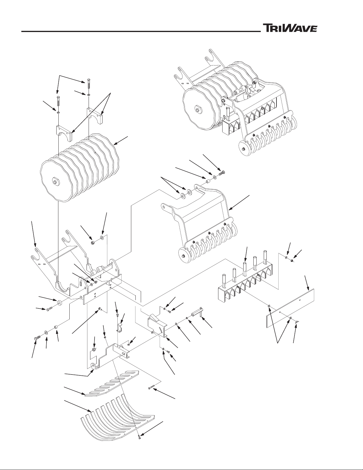
PARTS LISTS
™
™
4
1
(SEE NOTE A)
3
2
(SEE NOTE B)
3
BLADE
REEL
ASSEMBL
Y
PACKER
WHEEL
ASSEMBLY
5
6
7
8
9
10
1
1
14
21
12
13
26
10
22
22
25
23
15
16
17
18
19
20
18
27
28
29
30
20
32
31
18
PL85851-01REVB
23
23
24
16
22
Cutting Head Assembly
32
85851 Rev B
Page 33

PARTS LISTS
™
™
Cutting Head Assembly
Item Part Description Qty.
No. No.
1 664553 Frame, Blade Support, Includes Bearing Top Caps (See Note A) .......... 1
2 664588 Screw, Hex Head, 3/8”-16 x 3-1/2” (See Note B) ...................................4
3 446142 Washer, Lock, 3/8” .................................................................................. 4
4 660836 Washer, Flat, 49/64” ID x 1-5/16” OD x 3/32” Thick ................................ 4
5 664364 Box, Seed Distribution .............................................................................1
6 658240 Bolt, Carriage, 5/16”-18 x 3/4” ................................................................. 2
7 453009 Washer, Flat, 5/16” SAE .......................................................................... 2
8 444808 Nut, Hex, 5/16”-18 Nylock ....................................................................... 2
9 664370 Cover, Plexiglas ......................................................................................1
10 453023 Washer, Flat, 9/32” ID x 5/8” OD x 1/16” Thick ....................................... 5
11 658238 Wing Nut, 5/16”-18 .................................................................................. 2
12 664626 Plate, Finger Support ..............................................................................1
13 664625 Plate, Depth ............................................................................................ 1
14 664573 Pivot, Depth Adjuster ............................................................................... 1
15 400112 Screw, Hex Head, 1/4”-20 x 1” ................................................................ 3
16 444830 Nut, Hex, 1/4”-20 Nylock ......................................................................... 5
17 400442 Screw, Hex Head, 1/2”-20 x 1-1/2” ..........................................................2
18 660832 Washer, Flat, 1/2” SAE ............................................................................ 6
19 664587 Tube, Spacer ...........................................................................................2
20 444816 Nut, Hex, 1/2”-20 Nylock ......................................................................... 4
21 664582 Clamp, Handle ........................................................................................ 1
22 446128 Washer, Lock, 1/4” .................................................................................. 5
23 400106 Screw, Hex Head, 1/4”-2- x 5/8” ..............................................................6
24 664838 Indicator, Depth Gauge ........................................................................... 1
25 400118 Screw, Hex Head, 1/4”-20 x 1-3/4” ..........................................................1
26 664619 Nut, Depth Adjustment Lock .................................................................... 1
27 400266 Screw, Hex Head, 3/8”-16 x 1-1/2” ..........................................................2
28 664363 Spacer ..................................................................................................... 2
29 660820 Washer, Flat, 3/8” SAE ............................................................................ 2
30 444810 Nut, Hex, 3/8”-16 Nylock ......................................................................... 2
31 400446 Screw, Hex Head, 1/2”-20 x 2” ................................................................ 2
32 664586 Tube, Spacer ...........................................................................................2
85851 Rev B
NOTE A: Bearing Top Caps Included With Blade Support Frame. Do Not Mix Or
Exchange Caps From One Side To Other Side Or To Another Cutting Head
Assembly. Caps are matched with Bottoms.
NOTE B: Torque Screws To 180 To 200 Inch Pounds
(15 to 16.7 ft/lbs - 20.3 to 22.6 Nm)
33
Page 34
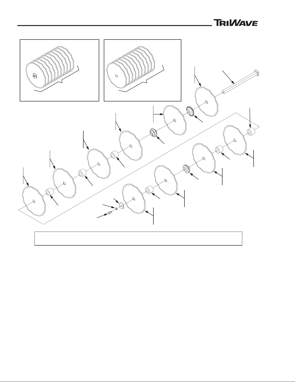
PARTS LISTS
™
™
10
7
8
9
1
1
13
13
14
15
16 (SEE NOTE A)
PL85851-05REVB
12
NOTE A: USE LOCTITE
®
ON SCREW THREADS
TORQUE TO 50 - 60 FT/LBS
(67.8 - 81.3 Nm)
1 - STANDARD
2 - GREENS
3 - NOTCHED
COMPLETE BLADE ASSEMBLY
4 - STANDARD
5 - GREENS
6 - NOTCHED
SET OF 10 BLADES
13
13
13
12
13
7
8
9
7
8
9
7
8
9
7
8
9
7
8
9
7
8
9
7
8
9
7
8
9
7
8
9
Blade Assembly
Item Part Description Qty.
No. No.
1 87504 Blade Assembly, Standard, Includes Standard Blades, Bearings,
Spacers, Sprocket, Axle and Hardware ............................................... 1
2 87505 Blade Assembly, Greens, Includes Greens Blades, Bearings,
Spacers, Sprocket, Axle and Hardware ............................................... 1
3 87508 Blade Assembly, Notched 8 Pt, Includes Notched Blades, Bearings,
Spacers, Sprocket, Axle and Hardware ............................................... 1
4 87500 Blade Set, Standard, 12-1/2” Circular (Set of 10) ................................... 1
5 87502 Blade Set, Greens, 12-1/2” Circular (Set of 10) ...................................... 1
6 87506 Blade Set, Notched, 12-1/2” Circular (Set of 10) .................................... 1
7 87501 Blade, Standard, 12-1/2” Circular (1 Each) ............................................. 1
8 87503 Blade, Greens, 12-1/2” Circular (1 Each) ............................................... 1
9 87507 Blade, Notched, 8 Pt, 12-1/2” Circular (1 Each) ..................................... 1
10 664329 Axle .........................................................................................................1
11 664332 Sprocket, Drive ........................................................................................1
12 664362 Bearing Assembly, Includes Bearing and Bushing .................................. 2
13 664359 Spacer, Plastic ........................................................................................6
14 665180 Plate, End Cap ........................................................................................ 1
15 446154 Washer, Lock, 1/2” .................................................................................. 1
16 400406 Screw, Hex Head, 1/2”-13 x 1-1/4” (See Note A) ...................................1
34
85851 Rev B
Page 35
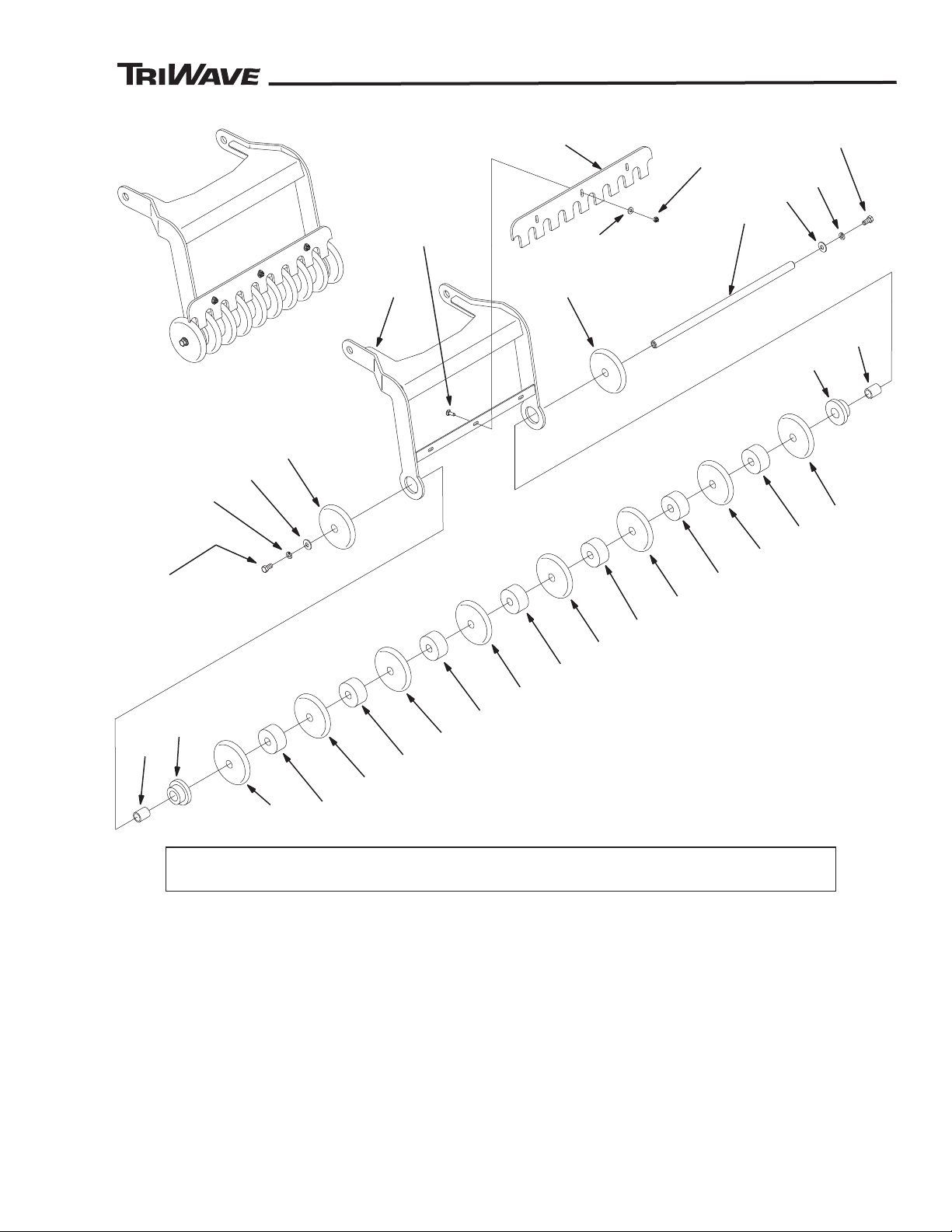
™
™
Packer Wheel Assembly
1
2
3 - SEE NOTE A
4
5
3
(SEE NOTE A)
4
5
6
6
7
8
7
8
6 9
6
9
6
9
6
9
6
9
6
9
6
9
6
10
1
1
12
13
PL85851-09REVA
NOTE A: USE LOCTITE® ON SCREW THREADS
TORQUE TO 20 - 25 FT/LBS (27.1 - 33.9 Nm)
PARTS LISTS
85851 Rev B
Item Part Description Qty.
No. No.
1 664669 Frame, Packer Wheel Arm ...................................................................... 1
2 664665 Rod, Packer Wheel Axle .........................................................................1
3 400262 Screw, Hex Head, 3/8”-16 x 1” (See Note A) .......................................... 2
4 446142 Washer, Lock, 3/8” .................................................................................. 2
5 452008 Washer, Flat, 7/16” ID x 1” OD x 5/64” Thick ..........................................2
6 664663 Disc, Packer Wheel ............................................................................... 10
7 664668 Spacer, .................................................................................................... 2
8 664664 Spacer, End, Packer Wheel .................................................................... 2
9 664667 Spacer, Center, Packer Wheel ................................................................ 7
10 664672 Scraper ....................................................................................................1
11 661467 Bolt, Carriage, 1/4”-20 x 3/4” ................................................................... 3
12 453023 Washer, Flat, 9/32” ID x 5/8” OD x 1/16” Thick ....................................... 3
13 444830 Nut, Hex, 1/4”-20 Nylock ......................................................................... 3
35
Page 36
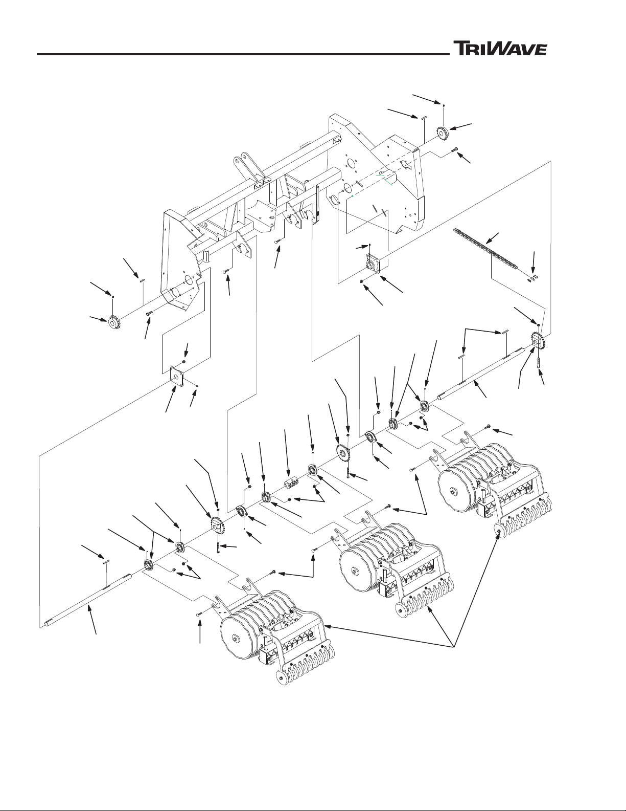
PARTS LISTS
™
™
1
2
4
CUTTING
HEAD
ASSEMBLIES
4
5
5
6
6
7
7
8
8
9
9
15
15
10
1
1
12
12
12
14
13
13
13
11
17 (SEE NOTE A)
12
12
10
11
3
13
13
14
11
10
11
18
16
14
10
11
11
10
11
19
20
PL85851-10REVA
10
12
16
3
16
17 (SEE NOTE A)
17 (SEE NOTE A)
NOTE A - TORQUE TO 375 IN/LBS (31.25 FT/LBS - 42.4 Nm)
Cutter Head Drive Shafts
36
85851 Rev B
Page 37

PARTS LISTS
™
™
Cutter Head Drive Shafts
Item Part Description Qty.
No. No.
1 664387 Shaft, Jack, Cutter Head Drive, Left Hand .............................................. 1
2 664388 Shaft, Jack, Cutter Head Drive, Right Hand ............................................ 1
3 664399 Bearing, 4 Bolt .........................................................................................2
4 415561 Screw, Set, 5/16”-24 x 5/16” .................................................................... 4
5 400374 Screw, Hex Head, 7/16”-20 x 1-1/2” ........................................................8
6 444832 Nut, Hex, 7/16”-20 Nylock ....................................................................... 8
7 499154 Key, Square, 1/4” x 1-1/2” ....................................................................... 2
8 664395 Sprocket, 60B15 ......................................................................................2
9 415553 Screw, Set, 5/16”-18 x 5/16” .................................................................. 10
10 658541 Bearing, Flange, Includes Set Screws and Flangettes ........................... 8
11 499051 Screw, Set, 1/4”-28 x 1/4” ...................................................................... 16
12 664220 Bolt, Carriage, 3/8”-16 x 1-1/4” Short Neck ........................................... 16
13 444810 Nut, Hex, 3/8”-16 Nylock (See Note A) .................................................16
14 665359 Clamp Collar (Sprocket) RC-50, 24 Tooth ............................................... 3
15 665363 Key, Square, 1/4” x 2” .............................................................................3
16 400202 Screw, Hex Head, 5/16”-18 x 3” .............................................................. 3
17 444808 Nut, Hex, 5/16”-18 Nylock (See Note A) .................................................3
18 665361 Coupling, Split, Includes Socket Head Screws .......................................1
19 664545 Chain, RC-50 x 62 Pitch, Includes Master Link .......................................3
20 665420 Link, Master, RC-50, O-Ring Sealed .......................................................3
NOTE A: Torque Screws To 375 Inch Pounds
(31.25 ft/lbs - 42.4 Nm)
85851 Rev B
37
Page 38
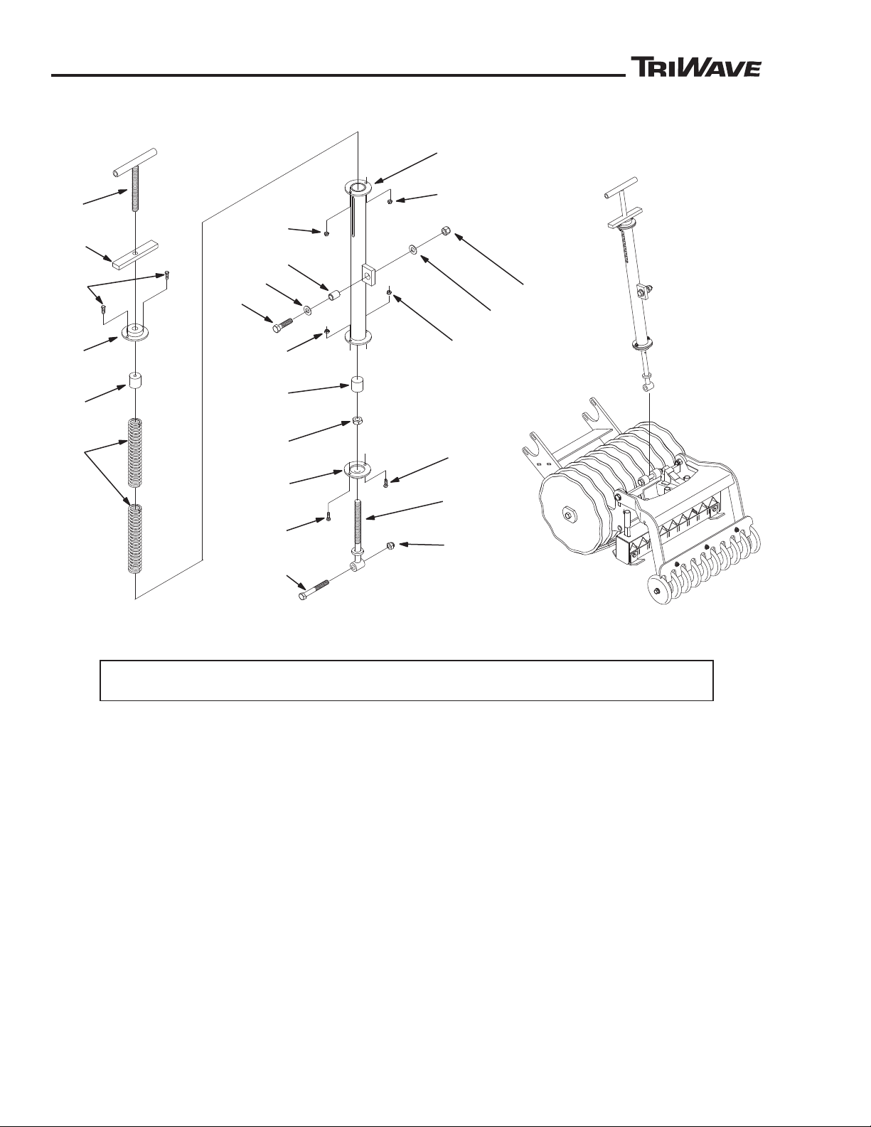
PARTS LISTS
™
™
1
2
3
4
5
6
7
8
8
8
8
9
10
1
1
12
3
3
13
14
15
14
17
16
17
PL85851-03
Down Pressure Assembly
Item Part Description Qty.
No. No.
1 664347 T-Handle .................................................................................................. 1
2 664357 Bar, Hold Down Jam Nut .........................................................................1
3 400108 Screw, Hex Head, 1/4”-20 x 3/4” ............................................................. 4
4 664343 End Cap, Threaded ................................................................................. 1
5 664350 Spacer, Upper Spring Gauge .................................................................. 1
6 664358 Spring, Compression ...............................................................................2
7 664339 Tube, Hold Down .................................................................................... 1
8 444830 Nut, Hex, 1/4”-20 Nylock ......................................................................... 4
9 664351 Spacer, Lower Spring Stop .....................................................................1
10 443826 Nut, Hex, 5/8”-11 Jam ............................................................................. 1
11 664345 End Cap .................................................................................................. 1
12 664352 Connecting Rod ...................................................................................... 1
13 664356 Bushing ...................................................................................................1
14 660832 Washer, Flat, 1/2” SAE ............................................................................ 2
15 400446 Screw, Hex Head, 1/2”-20 x 2” ................................................................ 1
16 400456 Screw, Hex Head, 1/2”-20 x 4” ................................................................ 1
17 444816 Nut, Hex, 1/2”-20 12 Nylock .................................................................... 2
38
85851 Rev B
Page 39
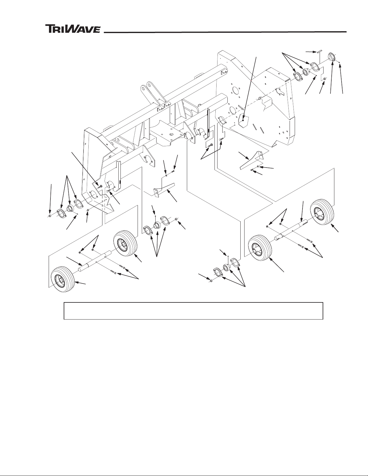
™
™
Front Rollers and Roller Scrapers
1
1
5
6
6
5
7
5
1
8
9
1
1
10
8
7
5
6
6
8
15
13
12
7
16
PL85851-07
15
14
3
3
4
2
4
2
1
1
8
16
14
PARTS LISTS
Item Part Description Qty.
No. No.
1 664828 Tire and Hub Assembly ........................................................................... 4
2 665301 Shaft, Roller ............................................................................................ 2
3 400196 Screw, Hex Head, 5/16”-18 x 2 ............................................................... 4
4 444808 Nut, Hex, 5/16”-18 Nylock ....................................................................... 4
5 658541 Bearing, Flange ....................................................................................... 4
6 499051 Screw, Set, 1/4”-28 x 1/4” ........................................................................ 8
7 664220 Bolt, Carriage, 3/8”-16 x 1-1/4” Short Neck ............................................. 8
8 444810 Nut, Hex, 3/8”-16 Nylock ......................................................................... 8
9 499154 Key, Square, 1/4” x 1-1/2” Long .............................................................. 1
10 665295 Sprocket, 35B26 ......................................................................................1
11 415553 Screw, Set, 5/16”-18 x 5/16” .................................................................... 2
12 665302 Bracket, Scrapper, Right Hand ................................................................ 1
13 665303 Bracket, Scrapper, Left Hand .................................................................. 1
85851 Rev B
14 400108 Screw, Hex Head, 1/4”-20 x 3/4” ............................................................. 4
15 453023 Washer, Flat, 9/32” ID x 5/8” OD x 1/16” Thick ....................................... 4
16 444830 Nut, Hex, 1/4”-20 Nylock ......................................................................... 4
39
Page 40
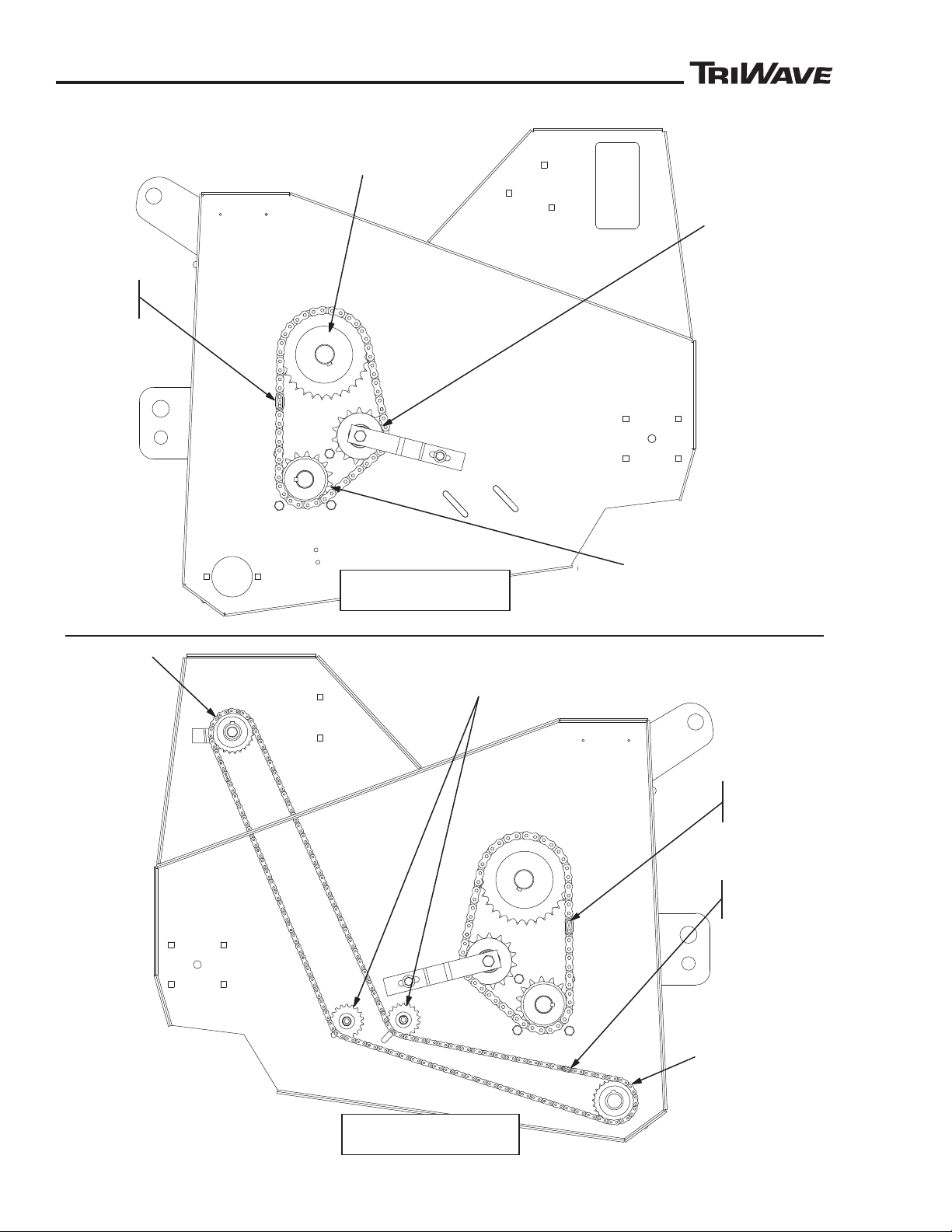
PARTS LISTS
™
™
1
2
SEEDER
BOX
SPROCKET
SEEDER DRIVE CHAIN
IDLER SPROCKETS
FRONT ROLLER
SEEDER DRIVE
SPROCKET
3
4
CUTTER HEAD
DRIVE
SPROCKET
PTO DRIVE SHAFT SPROCKET
CUTTER DRIVE
IDLER
SPROCKET
PL85851-11REVA
1
2
LEFT SIDE CHAINS
RIGHT SIDE CHAINS
Chains and Chain Idlers
40
85851 Rev B
Page 41
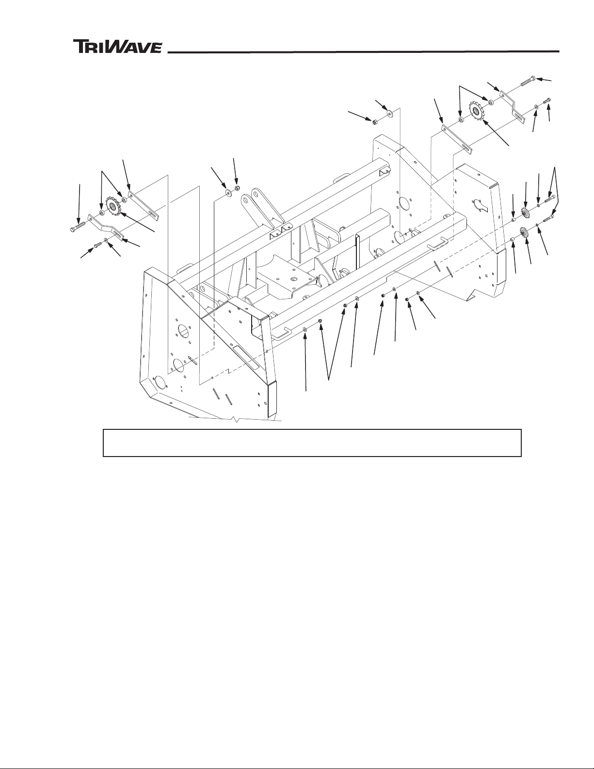
™
™
Chains and Chain Idlers
11
10
10
11
6
8
6
9
7
15
16
17
18
19
14
19
14
16
17
18
PL85851-12
5
7
13
12
9
13
8
5
12
13
13
14
PARTS LISTS
Item Part Description Qty.
No. No.
1 664544 Chain, RC-60 x 46 Pitch, Includes Master Link ....................................... 2
2 660437 Link, Master, RC-60 ................................................................................2
3 664546 Chain, RC-35 x 244 Pitch, Includes Master Link ..................................... 1
4 661664 Link, Master, RC-35 ................................................................................1
5 665306 Sprocket, 60I15H1/2 ............................................................................... 2
6 665360 Spacer, Idler Sprocket .............................................................................4
7 665298 Bracket, Tensioner ..................................................................................2
8 665299 Plate, Tensioner ......................................................................................2
9 400452 Screw, Hex Head, 1/2”-20 x 3” ................................................................ 2
10 499002 Washer, Flat, 1/2” ID x 1-1/2” OD x 5/32” Thick ...................................... 2
11 444816 Nut, Hex, 1/2”-20 Nylock ......................................................................... 2
12 400266 Screw, Hex Head, 3/8”-16 x 1-1/2” ..........................................................2
13 452006 Washer, Flat, 3/8” ID x 7/8” OD x .078 Thick ........................................... 4
14 444810 Nut, Hex, 3/8”-16 Nylock ......................................................................... 4
85851 Rev B
15 665292 Screw, Hex Head, 3/8”-16 x 2-1/2” ..........................................................2
16 499021 Washer, Flat, 25/64” ID x 5/8” OD x 1/16” Thick ..................................... 2
17 661649 Sprocket, Idler, 18 Tooth, RC-35 ............................................................. 2
18 664661 Spacer ..................................................................................................... 2
19 499167 Washer, Flat, 25/64” ID x 3/4” OD x 9/64” Thick ..................................... 2
41
Page 42
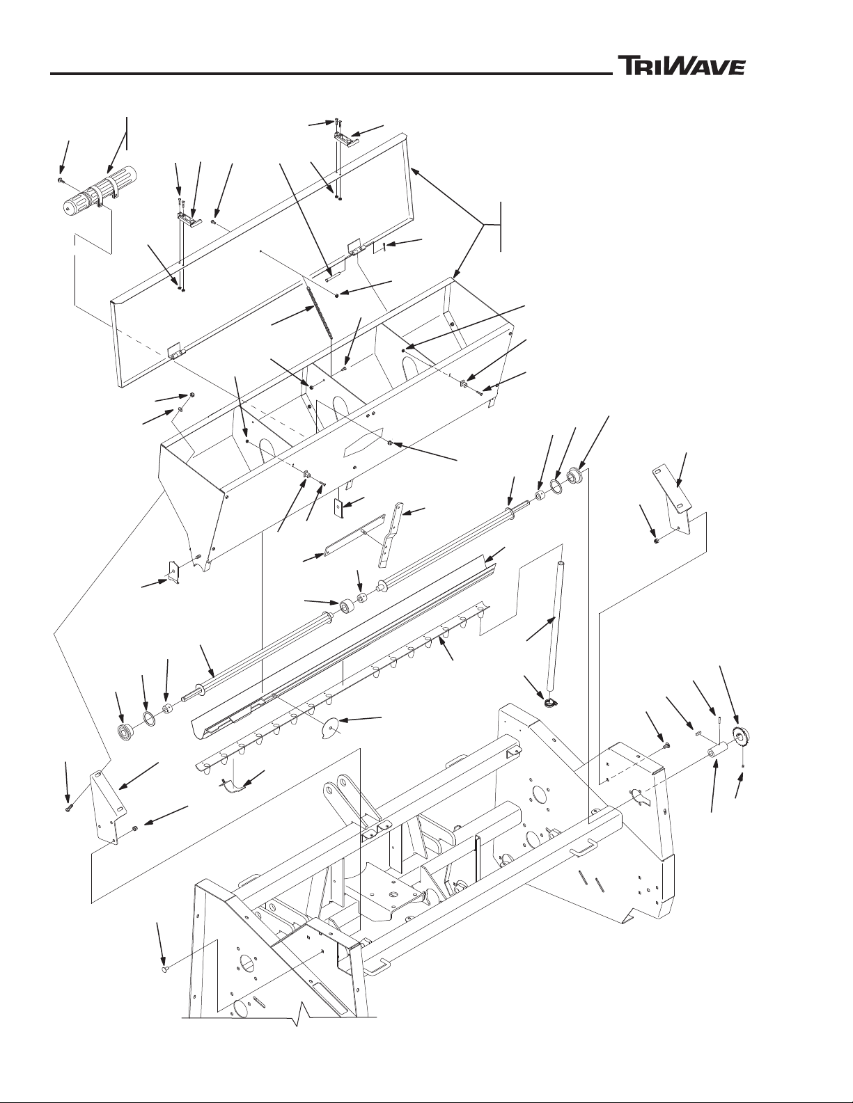
PARTS LISTS
™
™
1
2
3
4
5
9
7
8
6
8
9
10
11
12
13
14
15
31
32
32
34
35
33
35
37
28
PL85851-13REVA
24
25
26
29
19
20
20
30
34
33
18
36
33
22
21
17
23
16
1922 21
23
23
22
39
21
22
21
23
40
42
27
41
38
Seed Box
42
85851 Rev B
Page 43

PARTS LISTS
™
™
Seed Box
Item Part Description Qty.
No. No.
1 665295 Sprocket, 35B26 ......................................................................................1
2 415553 Screw, Set, 5/16”-18 x 5/16” .................................................................... 2
3 664627 Sleeve .....................................................................................................1
4 461385 Pin, Spring, 3/16” x 1-1/4” .......................................................................1
5 499423 Key, Square, 1/4” x 7/8” ..........................................................................1
6 664615 Angle Support, Seed Box, Right Hand .................................................... 1
7 664616 Angle Support, Seed Box, Left Hand ......................................................1
8 444810 Nut, Hex, 3/8”-16 Nylock ......................................................................... 5
9 657766 Bolt, Carriage, 3/8”-16 x 3/4” ................................................................... 5
10 400260 Screw, Hex Head, 3/8”-16 x 7/8” ............................................................. 4
11 446142 Washer, Lock, 3/8” ..................................................................................4
12 443110 Nut, Hex, 3/8”-16 ..................................................................................... 4
13 664600 Seed Box, Includes Box and Cover, Without Seed Gate ........................ 1
14 664601 Seed Box, Without Cover and Seed Gate ...............................................1
15 664610 Cover, Seed Box ..................................................................................... 1
16 664922 Pin, Clevis ...............................................................................................2
17 460028 Pin, Cotter, 1/8” x 1” ................................................................................ 2
18 665181 Chain, Double Loop, 10” Long ................................................................1
19 400104 Screw, Hex Head, 1/4”-20 x 1/2” ............................................................. 2
20 444830 Nut, Hex, 1/4”-20 Nylock ......................................................................... 5
21 662134 Latch, Draw (Latch and Keeper) .............................................................2
22 662135 Screw, Slotted Round, #10-24 x 1” .........................................................6
23 499244 Nut, Hex, #10-24 KEPS .......................................................................... 6
24 662885 Tube, Manual (Tube and Cap) ................................................................ 1
25 662901 Clamp, Loop ............................................................................................ 2
26 661619 Screw, Hex Head, 1/4”-20 X 5/8” Whizlock ............................................. 2
27 661620 Nut, Hex, 1/4”-20 Whizlock ..................................................................... 2
28 664624 Tube, Clear Vinyl, 5/8” ID x 24” Long .................................................... 15
29 665182 Clamp, Hose, 1” ....................................................................................15
85851 Rev B
SEED BOX AND SEED GATE SERVICE PARTS
30 665373 Bottom and Slide Assembly, 5 Foot - 15 Opening (14583-27) ................1
31 665374 Spout Plate, 5 Foot - 15 Opening (14583-30) ......................................... 1
32 665375 Rotor Bar, Rubber (14569-4) ................................................................... 2
33 665376 Journal, Rotor Bar (14071) ......................................................................3
34 660944 Gasket, End Bearing (M05-0773-000) ....................................................2
35 660943 Bearing, End (140692) ............................................................................ 2
36 665377 Bearing, Center (140694) ........................................................................1
37 661661 Gauge, Seed Dial Cam (0906375-C1) .................................................... 1
38 665502 Mount, Shutoff Lever (14853-12B) .......................................................... 1
39 665503 Lever, Shutoff (1408030-5B) ................................................................... 1
40 665504 Retainer, End Bearing (09063146) .......................................................... 2
41 665505 Retainer Center Bearing (140677) .......................................................... 1
42 665506 Retaining Clip, Spout Mounting Plate (14583-14) ................................... 3
43
Page 44
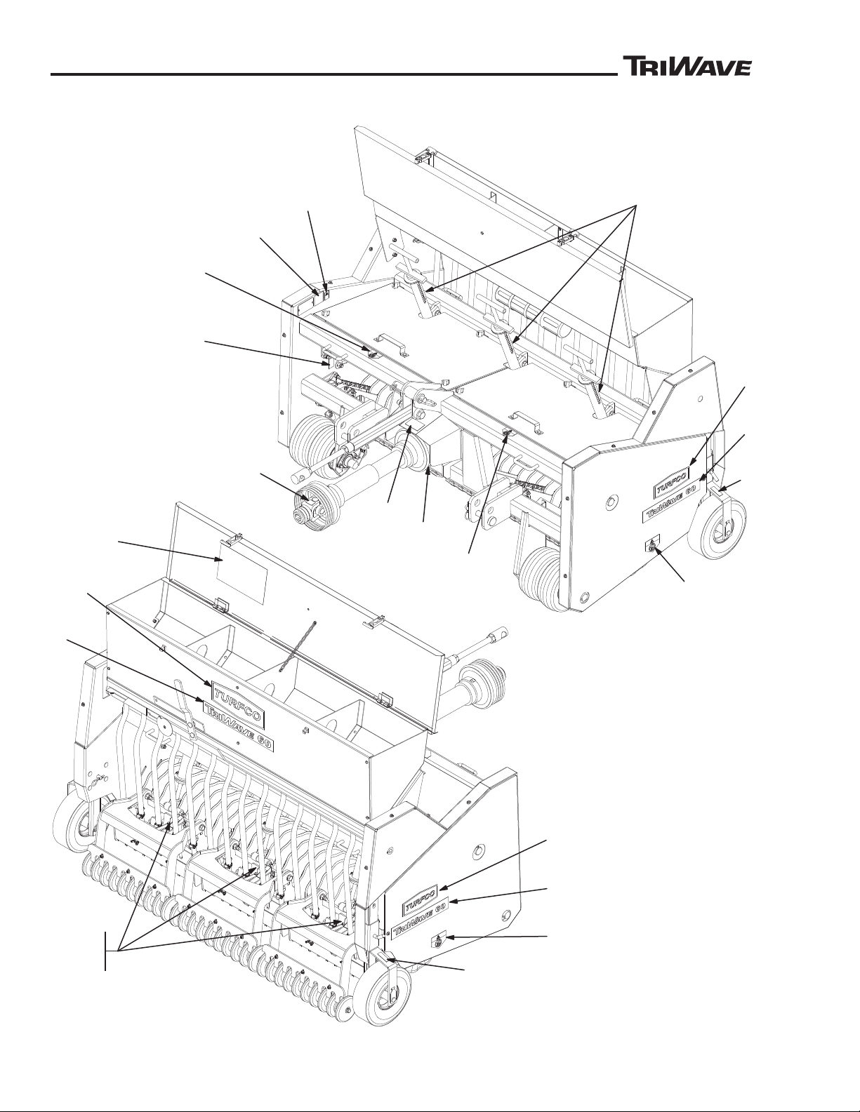
PARTS LISTS
™
™
11
PL85851-14REVA
10
8
4
9
7
3
10
4
20 - OPERATOR AND
PARTS MANUAL
5
15
8
13
7
12
17
18
14
12
3
19
1
TURFCO
TURFCO
TURFCO
Decals
44
85851 Rev B
Page 45

PARTS LISTS
™
™
Decals
Item Part Description Qty.
No. No.
1 660972 Decal, Turfco Logo, 12”, Green and Almond ........................................... 1
2 664682 Decal Sheet, Product Identification, TriWave Seeder,
Includes Items 3 Thru 5 ......................................................................... 1
3 Decal, Turfco Logo, 7”, Green and Almond .......................................... 2
4 Decal, TriWave Logo, 12” ..................................................................... 2
5 Decal, TriWave Logo, 15” ..................................................................... 1
6 664836 Decal Sheet, Warnings and Controls, PTO Seeder,
Includes Items 7 Thru 15 ....................................................................... 1
7 Decal, Hand Hazard Warning ..............................................................2
8 Decal, Foot Hazard Warning ................................................................2
9 Decal, PTO Hazard Warning ................................................................ 1
10 Decal, Storage Only Warning ............................................................... 2
11 Decal, Down Pressure Scale ...............................................................3
12 Decal, Grease Fitting, PTO Shaft ......................................................... 2
13 Decal, Grease Fitting, Drive Shaft Bearings ........................................2
14 Decal, Read Manual Warning .............................................................. 1
15 Decal, Product Identification ................................................................1
16 665426 Decal Sheet, Depth Adjusters, Includes Items 17 and 18 ....................... 1
17 Decal, Depth Setting Scale .................................................................. 3
18 Decal, Pointer, Depth Setting Scale ..................................................... 3
19 665288 Decal Sheet, Seed Application Chart ...................................................... 1
20 665365 Manual, Operator and Parts Lists, Revision B, TriWave Seeder 85851 .1
85851 Rev B
45
Page 46
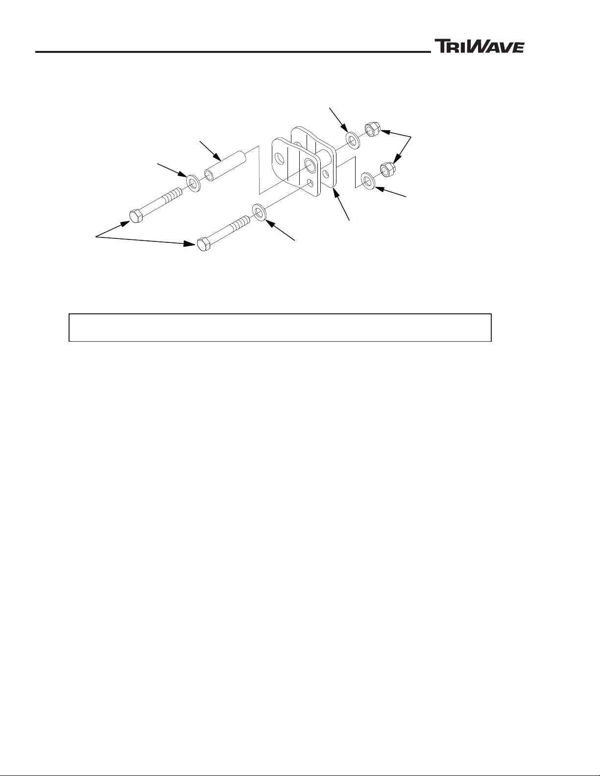
PARTS LISTS
™
™
1
2
3
4
5
5
5
5
PL85851-16
6 - INSTALLATION
INSTRUCTION SHEET
Item Part Description Qty.
No. No.
Optional TriWave Hitch Extension Kit - Product Number 86173
1 665233 Extension, TriWave ................................................................................. 2
2 665236 Sleeve, TriWave Extension ..................................................................... 2
3 665224 Screw, Hex Head, 3/4”-10 x 5” ................................................................ 4
4 664299 Nut, Hex, 3/4”-10 Nylock ......................................................................... 4
5 499227 Washer, Flat, 13/16” ID x 1-1/2” OD x 1/8” Thick .................................... 8
6 665232 Instruction Sheet, TriWave 60 Extension Kit 86173 ................................ 1
46
85851 Rev B
Page 47
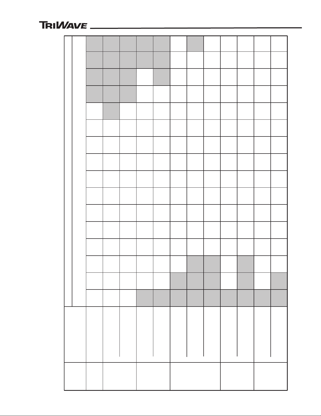
™
™
Bentgrass
Kentucky
Bluegrass
Fescue
Ryegrass
Mixtures
5 10 15 20 25 30 35 40 45 50 55 60 65 70 75 80
Approximate Pounds of Seed Per 1000 Square Feet at 3 MPH (Kilograms of Seed Per 92.9 Square Meters at 4.8 Km/h)
Cam Gauge Dial Setting
Penncross
0.40 0.55 1.0 1.4 2.1 2.8 3.7 4.7 5.9 7.5 8.8 9.8 11.2 11.3
0.15 0.25 0.35 0.45 0.65 0.85 1.2 1.7 2.2 2.6 3.2 3.8
Type
Of Seed
Variety
50% Bluegrass
50% Fescue
50% Bluegrass
50% Rye
Tall
Perennial
Hard
Creeping
Red
0.15 0.20 0.32 0.48 0.55 0.88 1.1 1.4 1.9 2.4 3.1 3.9 4.9 5.5 5.7
0.35 0.55 1.0 1.5 2.2 2.9 3.9 4.9 6.4 7.6 8.6 9.7 9.9
0.3 0.5 0.7 1.0 1.4 1.8 2.4 3.1 3.9 4.8 5.9 6.9 7.6 7.6
0.15 0.25 0.55 0.95 1.4 2.2 3.0 4.0 5.2 6.6 8.2 9.3 10.8 12.4 12.7
Annual
0.35 0.5 0.75 1.1 1.7 2.2 3.0 3.8 4.5 5.5 6.4 7.0 6.7
Bluegrass
Rough
0.45 0.9 1.5 2.3 3.4 4.5 6.1 7.3 8.8 10.9 13.0 15.0
0.15 0.35 0.55 1.1 1.7 2.4 3.1 3.8 5.2 6.2 7.4 8.4 9.7
Bermuda
0.15 0.45 1.1 1.8 3.2 4.2 5.9 7.9 9.7 12.1 14.7 18.4
Coated
Hulled
0.25 0.65 1.4 2.2 3.2 4.1 5.4 7.1 8.3 10.9 11.8 13.7
0.5 1.3 2.2 3.4 5.0 6.7 8.9 12.5 14.9 17.5 20.9
Pounds
(Kilograms)
(0.11) (0.3) (0.64) (1.0) (1.45) (1.85) (2.45) (3.22) (3.75) (5.9) (5.35) (4.4)
(0.23) (0.59) (1.0) (1.54) (2.26) (3.04) (4.04) (5.67) (6.75) (7.94) (9.48)
Pounds
(Kilograms)
Pounds
(Kilograms)
Pounds
(Kilograms)
(0.07) (0.21) (0.5) (0.82) (1.45) (1.91) (2.68) (3.58) (4.4) (5.49) (6.67) (8.35)
(0.07) (0.16) (0.25) (0.5) (0.77) (1.09) (1.41) (1.72) (2.36) (2.81) (3.35) (3.81) (4.40)
Pounds
(Kilograms)
Pounds
(Kilograms)
Pounds
(Kilograms)
Pounds
(Kilograms)
Pounds
(Kilograms)
Pounds
(Kilograms)
Pounds
(Kilograms)
Pounds
(Kilograms)
(0.21) (0.41) (0.68) (1.05) (1.54) (2.04) (2.77) (3.31) (3.99) (4.95) (5.89) (6.80)
(0.14) (0.22) (0.31) (0.45) (0.64 ) (0.82) (1.09) (1.41) (1.77) (2.18) (2.67) (3.12) (3.45) (3.45)
(0.07) (0.11) (0.16) (0.21) (0.3) (0.38) (0.54) (0.77) (0.99) (1.18) (1.45) (1.72)
(0.16) (0.25) (0.45) (0.68) (1.0) (1.31) (1.77) (2.22) (2.90) (3.45) (3.90) (4.4) (4.49)
(0.18) (0.25) (0.45) (0.64) (0.95) (1.27) (1.67) (2.13) (2.67) (3.4) (4.0) (4.5) (5.08) (5.12)
(0.07) (0.11) (0.25) (0.43) (0.64) (1.0) (1.36) (1.81) (2.36) (2.99) (3.72) (4.21) (4.9) (5.62) (5.76)
(0.07) (0.09) (0.15) (0.22) (0.25) (0.40) (0.5) (0.63) (0.87) (1.09) (1.41) (1.77) (2.22) (2.5) (2.58)
(0.16) (0.22) (0.34) (0.5) (0.77) (1.0) (1.36) (1.72) (2.04) (2.50) (2.90) (3.17) (3.04)
665288
PL85851-17
SEED APPLICATION CHART
SEED CHART
85851 Rev B
47
Page 48

®
™
TURFCO MFG. INC.
1655 101st Avenue NE
Minneapolis, Minnesota USA
55449-4420
Phone 763-785-1000 ● FAX 763-785-0556
Internet - www.turfco.com ● E-mail - [email protected]
Manual Number. 665365 Rev B 60” Seeder Printed in USA
Product Number 85851 091
1
 Loading...