

Page 1
Valve Plug Connectivity
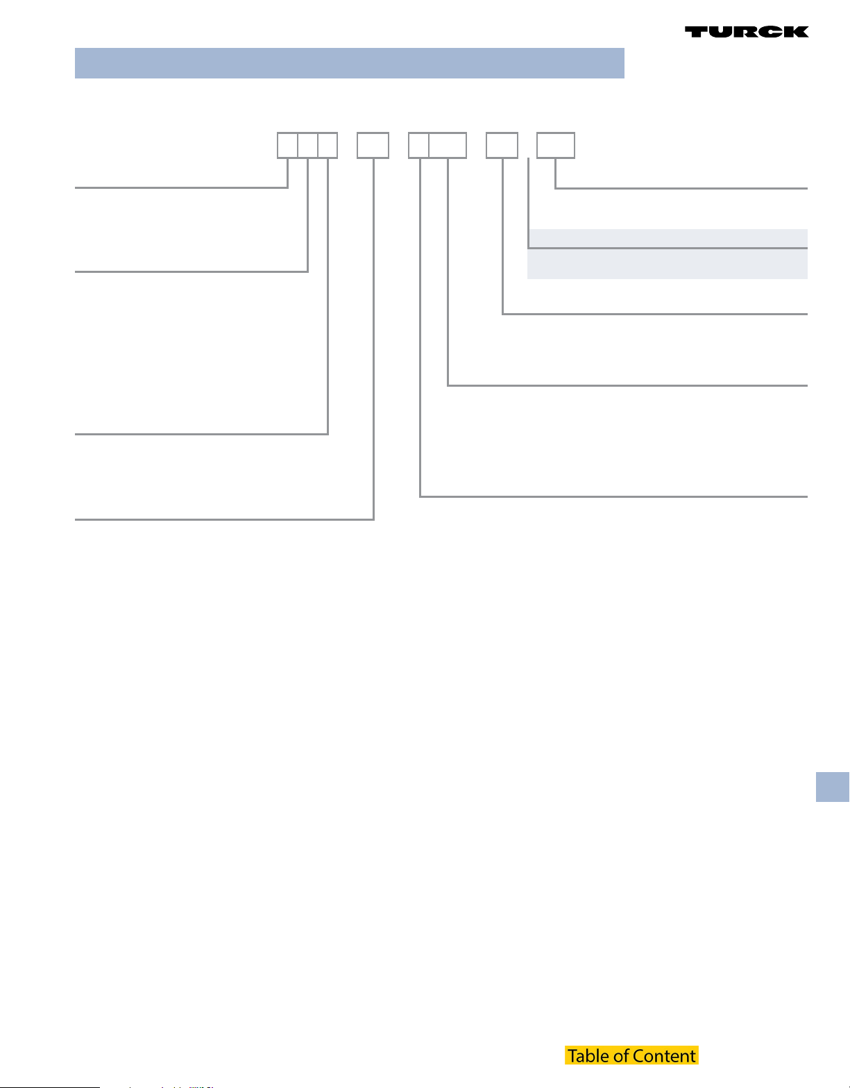
DIN 43650 Valve Cordset Part Number Key
Part Number Keys are to assist in IDENTIFICATION ONLY. Consult factory for catalog items not identied.
V A S 22 - F 653 - *M /S..
DIN 43650 Valve Cordset
T = cable exit on ground side
V = cable exit opposite ground side
H = cable exit opposite ground side
on top of plug
Housing Style
A = type “A” (27.5 x 27.5 mm) 18 mm contact
spacing
B = type “B” (21.5 x 28 mm) 10 mm contact
spacing
I = type “I” (21.5 x 28 mm) 11 mm contact
spacing
C8 = type “C” (16 x 16 mm 8 mm contact
spacing
C9 = type “C” (16 x 16 mm) 9.4 mm contact
spacing
Housing Color
G = Translucent grey
S = Translucent black
Y = Translucent yellow
(blank) = Clear
Designator for Receptacle
2 = 2 conductors, 1 ground
21 = 2 conductors, ground not connected
22 = 2 conductors, 1 ground, ground contacts parallel wired
3 = 3 conductors, 1 ground
4 = 3 conductors, 1 ground, additional wire for dual LED
Varieties
/S .. = consult factory, special
/S810 = Longer mounting screw
Insertion Point of Extension Cable Second Prex*
* Valve connector listed rst, other connector second
Example: VAS 22-F653-1M-RS 5.3T
Connection Type / Length in Meters
(blank) = eld wireable
FS 5.3 = integrated M12 Eurofast® connector
V1131 = integrated M8 Picofast® connector
Number of Wires / AWG / Color Codes
(blank) = adapter 644 = 4x18 AWG BN, BU, BK, WH
W = eld wireable connector 653 = 3x18 AWG BK, BK, GN/YE
544 = 4x18 AWG BN, WH, BK, BU 654 = 3x18 AWG BN, BU, BK
587 = 3x24 AWG BN, BU, BK 658 = 3x18 AWG RD/BK, RD/WH, GN
580 = 4x18 AWG BN, WH, BK, BU 669 = 3x18 AWG BK, BK, GN/YE
642 = 3x24 AWG BN, BU, BK
Wiring
A = straight through . . . . 0-220 VAC/DC
B = yellow LED . . . . . . . 24-48 VAC/DC
C = yellow LED . . . . . . . 110-220 VAC/DC
D = yellow LED/MOV. . . . 24-48 VAC/DC
E = yellow LED/MOV. . . . 110-220 VAC/DC
F = yellow LED/Diode . . . 24-48 VDC
K = two color LED for change over to switch . . . . . 24 VDC
L = yellow LED . . . . . . . . . 24 VAC/DC
M = yellow LED . . . . . . . . 48 VAC/DC
N = yellow LED . . . . . . . . 110 VAC/DC
P = yellow LED/MOV. . . . . 24 VAC/DC
R = yellow LED/MOV . . . . 48 VAC/DC
red = switch open position
green = switch closed position
B2007 T3
Valve Plug
 Loading...