

Page 1

Your Global Automation Partner
Operating instructions
TX100
HMI Series
Page 2

2
Hans Turck GmbH & Co. KG | T +49 208 4952-0 | F +49 208 4952-264 | more@turck.com | www.turck.com
Page 3

3
2018/09
1 About this document 5
1.1 Target Groups 5
1.2 Explanation of symbols 5
1.3 Additional Documents 5
1.4 Feedback about these instructions 6
2 product overview 6
2.1 Product Identication 7
2.2 Type Code 7
2.3 List of Available Devices 8
3 Standards and Approvals 8
3.1 Special Instruction for Use 8
4 Technical features 9
4.1 Technical Data 9
4.2 Environmental Conditions/Protection Class 9
4.3 Electromagnetic Compatibility (EMC)/Durability 10
4.4 Dimensions 11
4.4.1 TX104 12
4.4.2 TX107 12
4.4.3 TX110 14
5 Installing the HMI 15
5.1 Installation Environment 15
5.2 Mounting of the HMI 15
6 Connecting 16
6.1 Connecting the TX104 16
6.2 Connecting the TX107 16
6.3 Connecting the TX110 17
6.4 Serial port
18
6.5 Ethernet ports 19
6.6 USB port 19
7 Connecting the Power Supply 19
7.1 Grounding the device 20
8 Cleaning faceplates 21
9 Getting Started 21
9.1 Programming with TX VisuPro 21
10 Adapting the System Settings 22
10.1 Access the System Settings in User Mode 22
10.2 Access the System Settings in System Mode 23
11 Unpacking and Packing the Device 24
Table of Contents
Page 4

4
Hans Turck GmbH & Co. KG | T +49 208 4952-0 | F +49 208 4952-264 | more@turck.com | www.turck.com
11.1 TX104/TX107 24
11.2 TX110 25
12 Appendix: Accessories 25
12.1 Mounting Material/Power Supply Connector 25
12.2 USB/SD Accessory 25
Page 5
5
2018/09
1 About this document
These operating instructions describe the structure, functions and the use of the product and
will help you to operate the product as intended. Read these instructions carefully before using
the product. This is to avoid possible damage to persons, property or the device. Retain the instructions for future use during the service life of the product. If the product is passed on, pass
on these instructions as well.
1.1 Target Groups
These instructions are aimed at qualified personnel and must be carefully read by anyone
mounting, commissioning, operating, maintaining, dismantling or disposing of the device.
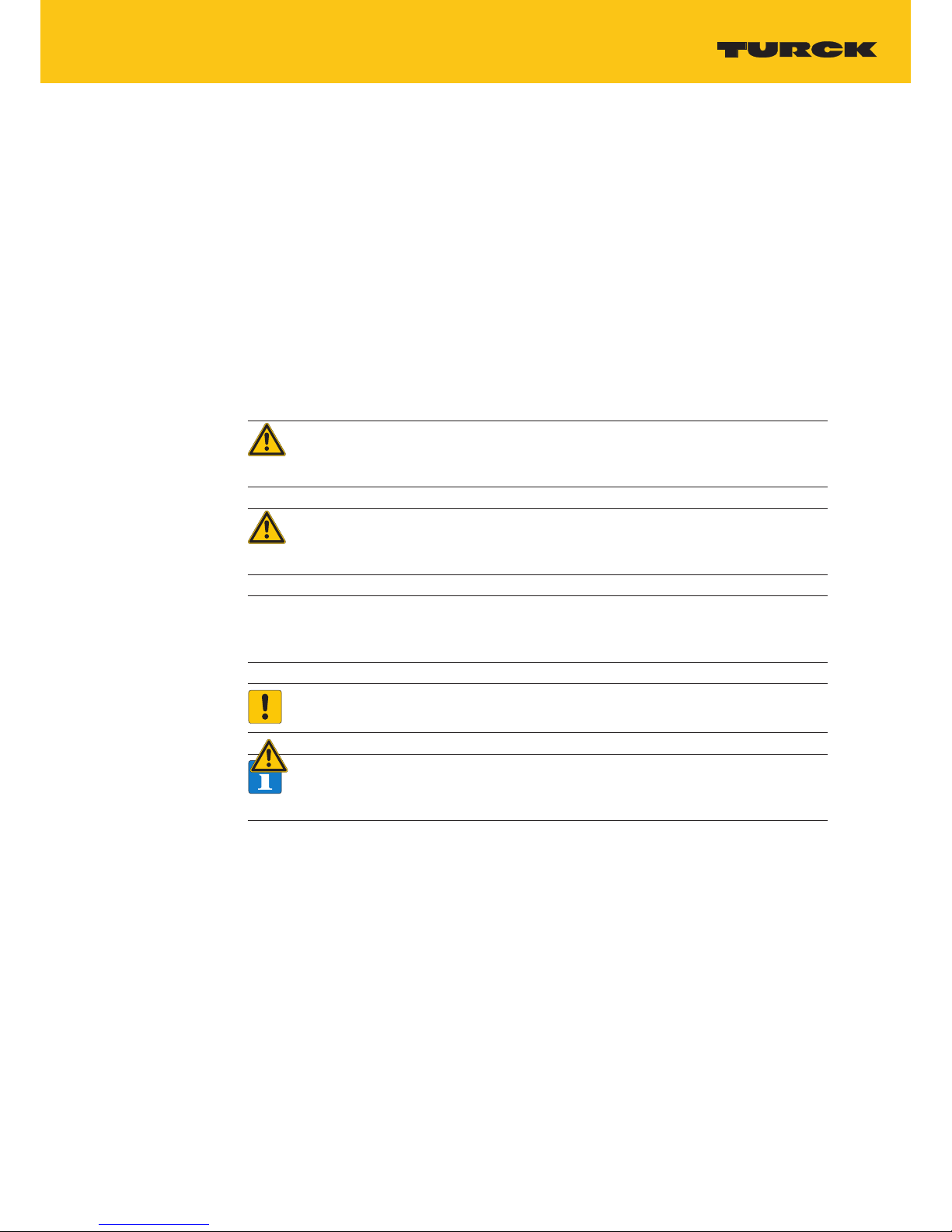
1.2 Explanation of symbols
The following symbols are used in these instructions:
DANGER!
DANGER indicates a dangerous situation with high risk of death or severe injury if not
avoided.
WARNING!
WARNING indicates a dangerous situation with medium risk of death or severe injury if
not avoided.
CAUTION!
CAUTION indicates a dangerous situation of medium risk which may result in minor or
moderate injury if not avoided.
NOTICE!
NOTICE indicates a situation which may lead to property damage if not avoided.
NOTE
NOTE indicates tips, recommendations and useful information on specific actions and
facts. The notes simplify your work and help you to avoid additional work.
CALL TO ACTION
This symbol denotes actions that the user must carry out.
RESULTS OF ACTION
This symbol denotes relevant results of actions.
Page 6

6
Hans Turck GmbH & Co. KG | T +49 208 4952-0 | F +49 208 4952-264 | more@turck.com | www.turck.com
About this document
1.3 Additional Documents
The following additional documents are available online at www.turck.com
■
Data sheet
■
Quick Start Guide
■
CAD data
■
Online help for TX Visu Pro
1.4 Feedback about these instructions
We make every effort to ensure that these instructions are as informative and as clear as possible. If you have any suggestions for improving the design or if some information is missing in
the document, please send your suggestions to techdoc@turck.com.
Page 7
7
2018/09
2 product overview
The graphical user interface of the TX100 HMIs is created with the visualization software Suite
TX VisuPro. The TX VisuPro software supports the following functions, among others:
■
Full vector graphic support, gallery of vector symbols and objects
■
Screen object dynamics
■
Multilanguage applications with TrueType fonts.
■
Data display (numerical, text, bargraph, analog gauges and graphic image formats)
■
Data acquisition and logging
■
Trend presentation
■
Alarm handling
■
Scheduler and timed actions
■
Recipes
■
Security and user management
■
Email and RSS feeds
■
Several communication drivers, multiple-driver communication capability
■
Remote monitoring and control with Client-Server functionality
■
On-line and Off-line simulation with TX VisuPro
■
Scripting language for automating HMI applications
■
Script debugger
2.1 Product Identication
The manual refers to the following models:
■
TX104 Operator interface with TFT color 4.3” widescreen display touchscreen
■
TX107 Operator interface with TFT color 7” widescreen display touchscreen
■
TX110 Operator interface with TFT color 10.1” widescreen display touchscreen
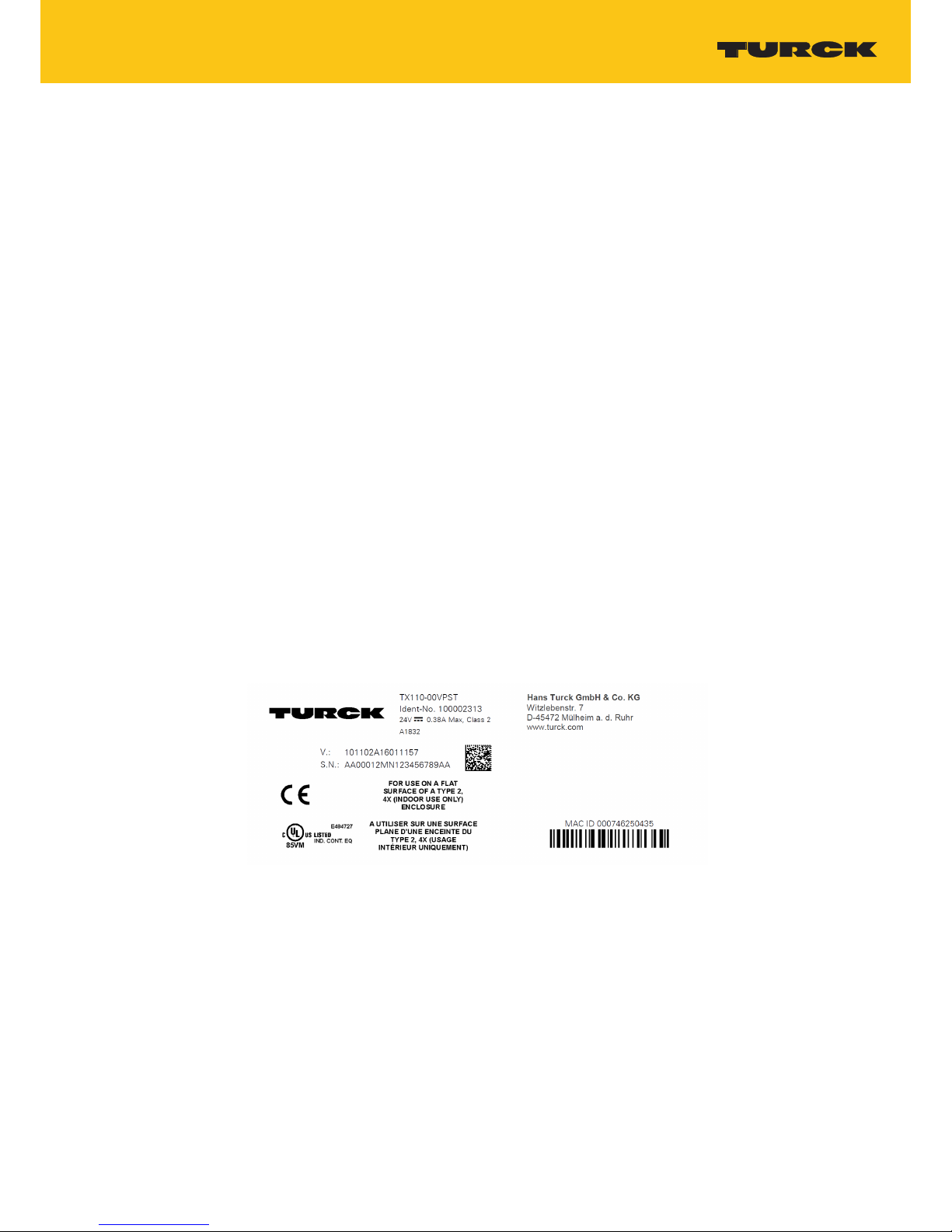
The type plate is located on the rear of the device.
An example of this plate is shown in the figure below:
TX110 Product model name
100002313 Product part number
1832 Year/week of production
AA… Serial number number
V… Internal version ID of the product
Page 8
8
Hans Turck GmbH & Co. KG | T +49 208 4952-0 | F +49 208 4952-264 | more@turck.com | www.turck.com
Standards and Approvals
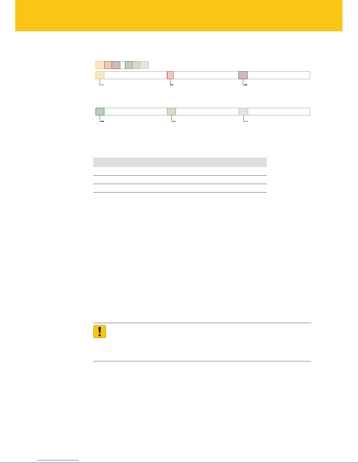
2.2 Type Code
TX 1 07 – 00 VP ST
TX
Product Series
Product series
TX Turck HMI/PLC
1
Series
Series
1 TX100 series
04
Screen Size
Screen size
04 4.3"
07 7"
10 10,1"
00
SPS
SPS
00 HMI without SPS functionality
XX
Display
Display
VP TX VisuPro Runtime
ST
Communication
Communication
ST Standard HMI protocol
Fig.1: Type Code TX100
2.3 List of Available Devices
Ident no. Device
100002311 TX104-00VPST
100002312 TX107-00VPST
100002313 TX110-00VPST
3 Standards and Approvals
The products have been designed for use in an industrial environment in compliance with the
2014/30/EU EMC Directive.
The products have been designed in compliance with:
EN 61000-6-4 EN 55011 Class A
EN 61000-6-3 EN 55022 Class B
EN 61000-6-2 EN 61000-4-2
EN 61000-6-1 EN 61000-4-3
EN 61000-4-4
EN 61000-4-5
EN 61000-4-6
EN 61000-4-8
EN 60079-0
EN 60079-7
EN 60079-11
NOTICE!
Operation in residential and commercial areas
Electromagnetic disturbances!
In case of the operation of the devices in residential and commercial areas, observe
the measurement values according to IEC-61000-6-3.
The products are in compliance with the Restrictions on Certain Hazardous Substances (RoHS)
Directive 2011/65/EU.
In compliance with the above regulations the products are CE marked.
Page 9
9
2018/09
3.1 Special Instruction for Use
■
The equipment shall only be used in an area of not more than pollution degree 2, as defined
in IEC/EN 60664-1.
■
The equipment shall be installed in an enclosure that provides a degree of protection not less
than IP 54 in accordance with IEC/EN 60079-7.
■
Transient protection shall be provided that is set at a level not exceeding 140 % of the peak
rated voltage value at the supply terminals to the equipment.
■
Care shall be taken not to allow layers of dust to form on the graphic panel in a way that
might cause the accumulation of static charges.
4 Technical features
4.1 Technical Data
TX104 TX107 TX110
Touchscreen technology Resistive
Display/backlight TFT Color /
LED
Colors 64 K
Brightness 200 Cd/m² typ.
Resolution 480 × 272 800 × 480 1024 × 600
Diagonal (inches) 4,3” widescreen (16:9) 7’’ widescreen (16:9) 10.1’’ widescreen (16:9)
Dimming Yes
CPU ARM Cortex - A8 – 300 MHz ARM Cortex - A8 – 1 GHz
Operating system Linux 3.12
Flash 2 GB 4 GB 4 GB
SD card slot No
RAM 256 MB DDR 512 MB DDR 512 MB DDR
Serial port 1× DB 9 (sofware configurable as RS232, RS485 or RS422)
Ethernet port 1 × 10/100 Mbit
USB Host port 1 × USB 2.0, max. 500 mA
Power supply DC Power Connector - AWG24 wire size - R/C Terminal Blocks (XCFR2), Female pitch 5.08
mm, torque 4.5 lb-in. 3 conductor 1,5 mm² wire size minimum, DC
Real time clock Yes
RTC backup Supercapacitor
Recipe memory Flash
Operating voltage 24 VDC (10…32 VDC)
Current consumption (at 24 VDC) 0.25 A 0.30 A 0.38 A
Weight 0.4 kg 0.6 kg 1 kg
Input protection Automatic
Accuracy RTC (at 25 °C) < 100 ppm
NOTE
For applications requiring compliance with EN 61131-2 and specifically in reference to 10 ms
voltage dips, the minimum power supply voltage is 18 VDC.
Page 10

10
Hans Turck GmbH & Co. KG | T +49 208 4952-0 | F +49 208 4952-264 | more@turck.com | www.turck.com
product overview
4.2 Environmental Conditions/Protection Class
Environmental conditions Standards
Operating temperature (surrounding air temperature) 0…+50 °C (vertical installation) EN 60068-2-14
Storage temperature -20…+70 °C EN 60068-2-14
Operating and storage humidity 5…85 % RH non-condensing EN 60068-2-30
Vibrations 5…9 Hz, 7 mm
p-p
9…150 Hz, 1 g
EN 60068-2-6
Shock ± 50 g, 11 ms, 3 pulses per axis EN 60068-2-27
Protection class
Front panel IP66, Type 2 and 4x (front); IP 20 (rear) EN 60529
NOTE
The front face of the unit installed in a solid panel meets the standards in the section
"Environmental conditions/protection class". However, oils that have no effect on the
TX100 may damage the unit. This can occur in applications where either vaporized oils
are present or where low viscosity cutting oil are allowed to adhere to the unit for long
periods of time. If the front face protection sheet on the TX200 is peeled off or damaged, this may lead to the ingress of oil into the unit and separate protection measures
are suggested.
If the installation gasket is used for a long period of time, or if the unit and its gasket
are removed from the mounting plate, the original level of the protection cannot be
guaranteed.
Page 11

11
2018/09
4.3 Electromagnetic Compatibility (EMC)/Durability
Electromagnetic compatibility (EMC)
Radiated disturbance test Class A EN 55011
Electrostatic discharge immunity test 8 kV (air electrostatic discharge)
4 kV (contact electrostatic discharge)
EN 61000-4-2
Radiated, radio-frequency,
electromagnetic field immunity test
80 MHz …1 GHz, 10 V/m
1,4 GHz … 2 GHz, 3 V/m
2 GHz … 2.7 GHz, 1 V/m
EN 61000-4-3
Burst immunity test ± 2 kV DC power port
± 1 kV signal line
EN 61000-4-4
Surge immunity test ± 0,5 kV DC power port (line to earth)
± 0,5 kV DC power port (line to line)
± 1 kV signal line (line to earth)
EN 61000-4-5
Immunity to conducted disturbances
inducted by radiofrequency field
0.15…80 MHz, 10 V EN 61000-4-6
Power frequency magnetic field
immunity test
Enclosure, 50/60Hz, 30A/m EN 61000-4-8
Voltage dips, short interruptions
and voltage variations immunity test
Port: AC mains;
Level:
100 % duration: 1 cycle and 250 cycles (50 Hz);
40 % duration: 10 cycles (50 Hz);
70 % duration: 25 cycles (50 Hz);
Phase: 0°-180°
Test executed on the 230 VAC side of the power supply EN 61000-4-11
Durability information
Backlight service life (LED type) 20000 Hrs. or more
(Time of continuos operation until the brightness of the backlight reaches 50% of
the rated value when the sorrounding air temperature is 25 °C, see Note blow)
Front foil (without direct exposure to
sunlight or UV)
10 years if the surrounding air temperature is 25 °C
UV Resistance Indoor applications: After 300 hours cycled humidity in QUV accelerated weather-
ing, some yellowing and brittleness may be present.
Solvent resistance –Contact for 30 minutes at 21 °C, no visible effect:
Acetone, Butyl Cellosolve, Cyclohexanone, Ethyl Acetate, Hexane, Isopropyl Alcohol, MEK, Methylene Chloride, Toluene, Xylene
– Contact for 24 hours at 49 °C, no visible effect:
Coffee, Ketchup, Lemon Juice, Mustard (slight yellow stain), Tea, Tomato juice.
Touchscreen reliability > 1 milion operations
NOTE
Extended use in environments where the surrounding air temperature is 40 °C or higher may
degrade backlight quality/reliability/durability.
Page 12

12
Hans Turck GmbH & Co. KG | T +49 208 4952-0 | F +49 208 4952-264 | more@turck.com | www.turck.com
product overview
4.4 Dimensions
4.4.1 TX104
Fig.2: Dimensions TX104
Device A B L H D T
TX104 136 mm/5.35” 96 mm/3.78” 147 mm/5.78” 107 mm/4.21” 29 mm/1.14” 5 mm/0.19”
Page 13

13
2018/09
4.4.2 TX107
Fig.3: Dimensions TX107
Device A B L H D T
TX107 176 mm/6.90” 136 mm/5.35” 187 mm/7.36” 147 mm/5.79” 29 mm/1.14” 5 mm/0.19”
Page 14

14
Hans Turck GmbH & Co. KG | T +49 208 4952-0 | F +49 208 4952-264 | more@turck.com | www.turck.com
product overview
4.4.3 TX110
Fig.4: Dimensions TX110
Device A B L H D T
TX110 271 mm/10.66” 186 mm/7.32” 282 mm/11.10” 197 mm/7.75” 29 mm/1.14” 6 mm/0.23”
Page 15

15
2018/09
5 Installing the HMI
5.1 Installation Environment
In order to meet the front panel protection class, proper installation procedure must be
followed:
■
The borders of the cutout must be flat
■
Screw up each fixing screw until the bezel corner get in contact with the panel.
■
The cut-out for the panel must be of the dimensions indicated in these instructions.
The equipment is not intended for continuous exposure to direct sunlight.
This might accelerate the aging process of the front panel film.
The equipment is not intended for installation in contact with corrosive chemical compounds.
Check the resistance of the front panel film to a specific compound before installation.
Do not use tools of any kind (screwdrivers, etc.) to operate the touch screen of the panel.
■
The IP66 is guaranteed only under the following conditions:
ū
Max. deviation from the plane surface to the cut-out: ≤ 0.5 mm
ū
Thickness of the case on which the equipment is mounted: 1,5 mm to 6 mm
ū
Max. surface roughness where the gasket is applied: ≤ 120 µm
Fig.5: HMI TX100 – Mounting
Page 16

16
Hans Turck GmbH & Co. KG | T +49 208 4952-0 | F +49 208 4952-264 | more@turck.com | www.turck.com
Connecting
5.2 Mounting of the HMI
NOTE
For all installation notes, please refer to the Installation Guide provided with the
product.
Place the fixing brackets contained in the fixing kit as follows:
Fig.6: Mouting the fixing brackets
Screw each fixing screw until the bezel corners get in contact with the HMI.
NOTE
Tightening torque: 75 Ncm or screw each fixing screw until the bezel corner gets in
contact with the panel.
6 Connecting
6.1 Connecting the TX104
Fig.7: TX104 – connection options
Connector Description
1 Serial port
2 Ethernet port
3 USB port
4 Power supply
Page 17

17
2018/09
6.2 Connecting the TX107
Fig.8: TX107 – connection options
Connector Description
1 Serial port
2 Ethernet port
3 USB port
4 Power supply
Page 18

18
Hans Turck GmbH & Co. KG | T +49 208 4952-0 | F +49 208 4952-264 | more@turck.com | www.turck.com
Connecting
6.3 Connecting the TX110
Fig.9: TX110 – connection options
Connector Description
1 Serial port
2 Ethernet port
3 USB port
4 Power supply
6.4 Serial port
The serial port is used to communicate with a PLC or with another type of device.
Different electrical standards are available for the signals in the PLC port connector: RS232,
RS422, RS485.
The serial port is software programmable. Make sure you select the appropriate interface in the
programming software.
Fig.10: Serial port
Page 19

19
2018/09
Pin RS232 RS422/RS485
1 GND GND
2 n.c. n.c.
3 TX CHA-
4 RX CHB-
5 n.c. n.c.
6 +5 VDC output +5V output
7 CTS CHB+
8 RTS CHA+
9 n.c. n.c.
NOTE
To operate in RS485, pins 4-3 and 8-7 must be connected externally.
The communication cable must be chosen for the type of device being connected.
6.5 Ethernet ports
The Ethernet ports have 2 status indicators.
Fig.11: Ethernet ports
Green Yellow RS422/RS485
ON OFF No LAN cable connected
BLINK (link active) ON LAN cable connected with 100 Mbit/s link
BLINK (link active) OFF LAN cable connected with 10 Mbit/s link-
6.6 USB port
Allowed formatting
Format FAT, FAT32
Max. size Limited by the FAT32 specification
≤ 4 GB for one single file
≤ 32 GB in total
Page 20

20
Hans Turck GmbH & Co. KG | T +49 208 4952-0 | F +49 208 4952-264 | more@turck.com | www.turck.com
Connecting the Power Supply
7 Connecting the Power Supply
The power supply terminal block is shown in the figure below.
Fig.12: Power supply terminal block
NOTE
Ensure that the power supply has enough power capacity for the operation of the
equipment.
7.1 Grounding the device
The unit must always be grounded to earth with A minimum of 1.5mm². Grounding helps to
limit the effects of noise due to electromagnetic interference on the control system.
The earth connection will have to be done using the grounding screw located near the power supply terminal block. The screw for the ground connection is marked with an engraved
ground symbol. Also connect terminal 3 on the power supply terminal block to ground.
The power supply circuit may be floating or grounded. If the power supply circuit is grounded,
connect to ground the power source common as shown in figure (see below) with a dashed
line.
When using the floating power scheme, note that the device internally connects the power
common to ground with a 1 MΩ resistor in parallel with a 4,7 nF capacitor.
The power supply must have double or reinforced insulation.
The suggested wiring for the power supply is shown below.
Page 21

21
2018/09
Fig.13: Power supply wiring
All the electronic devices in the control system must be properly grounded.
Grounding must be performed according to applicable regulations.
NOTE
The power connector is part of the scope of delivery and can be ordered as spare part,
see „12 Anhang: Zubehör“ S. 25.
8 Cleaning faceplates
The equipment must be cleaned only with a soft cloth and neutral soap product. Do not use
solvents.
9 Getting Started
9.1 Programming with TX VisuPro
The TX100-HMIs must be programmed with the software TX VisuPro. TX VisuPro is a software
tool that must be installed on a computer running Microsoft Windows.
There are two options to transfer a TX VisuPro application project to a HMI device:
■
Ethernet
Connect the HMI device to the computer with an Ethernet network connection. From TX
VisuPro choose the command Run/Download to target. You may have to ensure that the
proper firewall policy has been configured in the computer to allow TX VisuPro to access the
network.
■
USB
Create an Update Package using TX VisuPro and copy it to a USB Flash drive.
Page 22

22
Hans Turck GmbH & Co. KG | T +49 208 4952-0 | F +49 208 4952-264 | more@turck.com | www.turck.com
Adapting the System Settings
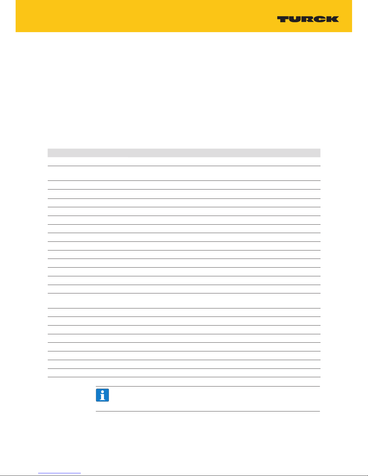
10 Adapting the System Settings
The TX100 HMIs have a system settings interface to allow configuration of system options.
The user interface of System Settings is based on HTML pages accessible from the HMI screen or
remotely using a Web browser Chrome V44 or higher using port 443.
To connect enter the address https://IP where IP is the IP address of the HMI device.
Default username is “admin”, default password is “admin”. Use navigation menu on the left side
of the screen to browse through the vailable options.
Fig.14: System settings
The active item of menu is highlighted on the left side of the screen. The right side shows related information and settings. Depending on the size of the HMI screen, both menu and content
of selected item may be shown on screen at the same time or not.
System Settings has 2 modes of operation:
Mode Description
User Mode TX VisuPro runtime is running or the HMI device is in “factory default” status.
System Mode TX VisuPro runtime is not running or the HMI device has a software failure. System
Mode includes all options available in User Mode and additionally includes commands
dedicated to system upgrade and recovery not available when running in User Mode.
10.1 Access the System Settings in User Mode
NOTICE!
System modification during operation
Undefined machine states due to device restart or loss of functionality!
Do not change system or network settings during operation.
Always stop the machine and disconnect the HMI when modifying the system
settings.
Page 23

23
2018/09
Status Description
Delivery
state
Press “System Setting” button on the HMI screen
TX VisuPro
runtime running
Recall context menu and select “System Settings”. To recall the context menu click
and hold any unused area of the touchscreen for a few seconds. Default hold time
is 2 seconds.
10.2 Access the System Settings in System Mode
NOTICE!
System modification during operation
Undefined machine states due to device restart or loss of functionality!
Do not change system or network settings during operation.
Always stop the machine and disconnect the HMI when modifying the system
settings.
Status Description
Normal
operation
If TX VisuPro runtime is not running: Press “System Setting” button on the device screen
to recall System Settings in User Mode. Select “Restart” -> “Config OS” to reboot in System
Mode. If TX VisuPro runtime is running: recall context menu and select “System Settings”.
To recall the context menu click and hold any unused area of the touchscreen for a few
seconds. Default hold time is 2 seconds to enter in System Settings in User Mode. Select
Select “Restart” -> “Config OS” to reboot in System Mode.
Recovery
operation
If the HMI is not responsive, use the so-called “tap-tap” procedure.
This procedure consists in tapping the surface of the touchscreen during the device
power-up phase. Tapping frequency must be high (2 Hz or more). Start tapping the
touchscreen as soon as power has been applied to the device. When the sequence has
been recognized, the system shows the message: “Tap Tap detected, Going to Config
Mode” on the screen.
System Settings includes options for basic settings of the device:
setting Description
Language Configure language used for System Setting menu only.
System Show information about platform, status and timers (like System on time, backlight on
time).
Logs Enable persistent log for BSP and allows exporting it.
Date & Time Change the device date and time, including time zone and NTP Server.
Network Configure IP Address of Ethernet interface and the other network settings like DNS, Gate-
way, DHCP, Hostname, routing and bridging.
Services Enable/disable services. Examples for services: OpenSSH server, Bridge, Cloud, Router,
SNMP and logging.
Management
Update of BSP components (Main OS, Config OS, Boot loader, XLoader), check for partitions consistence, update of splash screen, information about usage and size of partitions. The update of Main OS is available only in System Mode, the update of Config OS is
only in User Mode.
Page 24

24
Hans Turck GmbH & Co. KG | T +49 208 4952-0 | F +49 208 4952-264 | more@turck.com | www.turck.com
Unpacking and Packing the Device
Display Adjust display brightness, configure automatic backlight turnoff
Restart Restart the device. “Main OS” option restarts the device in User Mode, “Config OS” option
restarts the device in the System Mode showing System Settings.
Authentication
Configure password for administrator (“admin”) and for the standard user (“user”). Administrator has full access to System Settings (updates of BSP and other system components). Standard user has some limitations.
11 Unpacking and Packing the Device
11.1 TX104/TX107
Fig.15: Unpacking TX104/TX107
To repack the unit, please follow the instructions backwards.
11.2 TX110
Fig.16: Unpacking TX110
To repack the unit, please follow the instructions backwards.
Page 25

25
2018/09
12 Appendix: Accessories
12.1 Mounting Material/Power Supply Connector
Ident no. Type Description
100003186 TX100-MOUNT-07 Mounting material for TX100 for 4” and 7” devices:
4× fixing bracket
1 × power supply connector
100003187 TX100-MOUNT-10 Mounting material for TX100 for 10” devices:
11 × fixing bracket
1 × power supply connector
100002938 TX-PSC TX power supply onnector
12.2 USB/SD Accessory
Ident no. Type Description
6828025 SD CARD 2GB SD card, 2GB
6827348 USB 2.0 Industrial
Memory Stick
1GB , industrial USB stick
6827389 USB 2.0 EXTENSION 5MUSB 2.0 extension cable, male (A) to female (A), 5 meters
6827390 USB 2.0 EXTENSION
ACTIVE 5M
USB 2.0 extension cable, male (A) to female (A), with active
repeater, 5 meters
NOTE
Further accessories like field bus nodes, bus and supply cables, junction boxes, power
supplies etc. can be found on www.turck.com.
Page 26

26
Hans Turck GmbH & Co. KG | T +49 208 4952-0 | F +49 208 4952-264 | more@turck.com | www.turck.com
Page 27

100002665 | 2018/09
*100002665*
30 subsidiaries and over
60 representations worldwide!
www.turck.com
 Loading...