

Page 1

TEMPERATURSENSOR SERIE
TS400/500
TEMPERATURE
SENSOR SERIES
TS400/500
DÉTECTEUR
DE TEMPÉRATURE
SÉRIE
TS400/500
BEDIENUNGSANLEITUNG
INSTRUCTION
MANUAL
MODE D'EMPLOI
Hans Turck GmbH & Co.KG • D–45466 Mülheim an der Ruhr
S 1601/02
•
www.turck.com 0208
Page 2

TURCK – Ihre erste Adresse in der Industrieautomation
TURCK ist eine der global führenden Unternehmensgruppen auf
dem Sektor der Industrieautomation. Als Komplettanbieter für IP67Komponenten unterhalb der SPS liefert das Unternehmen über
13.000 Produkte aus den Bereichen der Sensor-, Interface-, Feldbusund Anschlusstechnik. Das vielfältige TURCK-Produktspektrum
bietet innovative Lösungen für jede Applikation.
TURCK - your fi rst choice in industrial automation
TURCK is one of the globally leading corporations in the industrial automation sector. As a full range supplier of IP67 components below the
controller level, the company offers more than 13,000 sensor, interface,
fi eldbus and connection products. TURCK’s versatile product spectrum
offers innovative solutions for all applications.
TURCK - Votre premier choix en matière d’automatisation
industrielle
TURCK est l’un des leaders dans l’automatisation industrielle. En tant
que fournisseur complet pour les composants IP67 au dessous du
niveau PLC, l’entreprise propose plus de 13000 détecteurs, interfaces
et produits issus de la technologie bus de terrain et de la connectique.
La gamme de produits TURCK particulièrement polyvalente offre des
solutions innovantes pour tous les types d’application.
Hans Turck GmbH & Co.KG • D–45466 Mülheim an der Ruhr
•
www.turck.com 0208
Page 3
TS…-…-2UPN8X-…
mpdl.gvodujpo
tuboebse
gvodujpot
26!t Npef!,!TfuNpef
Voj
Npef
pv2
Npef
TQ2
Npef
sQ2
Npef
pv3
Npef
TQ3
Npef
sQ3
Npef
vompdl
qvti.
cvuupot
Tfu
Npef
26!t
Foufs
Npef!,!Tfu
Npef!,!Tfu
21!t
Npef!,!Tfu
svo.npef
tipx
wbmvf
zft
op
wbmvf
tupsf
@
21!t
cvuupot
?!6!t
Tfu
mpdl
qvti.
MpdvMpd
26!t
op!gmbtijoh;gmbtijoh
dibohf
wbmvf
Tfu
Npef
fyufoefe
gvodujpot
26!t
Npef
Npef
Npef
Npef
Npef
Npef
Npef
Npef
Npef
Npef
FG
Ij
Mp
DpG
eT2
es2
eT3
es3
eBQ
Q.o
ejT
sFT
Npef
Npef
Npef!,!TfuTfu
Tfu
Npef
26!t
Foufs
Npef!,!Tfu
zft
op
tipx
wbmvf
tupsf
wbmvf
@
?!6!t
Tfu
op!gmbtijoh;gmbtijoh
fsbtf
wbmvf
)IJ!boe!MP*
ps
dibohf
wbmvf
Tfu
Npef
26!t
Tfu
26!t
TpG
Npef
Npef
26!t
Hans Turck GmbH & Co.KG • D–45466 Mülheim an der Ruhr
tipx
wbmvf
•
www.turck.com 0208
Page 4

TS…-…-2UPN8X-…
Para- Erläuterung Explanation Explication
meter
Loc sperren inhibit/lock Bloquer
uLoc entsperren enable/unlock Débloquer
Uni Temperatureinheit Unit of temperature Unitè de température
SP1 Schaltpunkt 1 Switch point 1 Point de commutation 1
rP1 Rückschaltpunkt 1 Release position 1 Point de comm. de ret. 1
ou1 Ausgangs- Switching output Fonction de sortie 1
funktion 1 function 1
SP2 Schaltpunkt 2 Switch point 2 Point de commutation 2
rP2 Rückschaltpunkt 2 Release position 2 Point de comm. de ret. 2
ou2 Ausgangs- Switching output Fonction de sortie 2
funktion 2 function 2
EF zusätzliche Additional Fonctions
Funktionen functions supplémentaires
Hi Maximalwert- Max-value Mémoire valeur
Speicher memory maximale
Lo Minimalwert- Min-value Mémoire valeur
Speicher memory minimale
CoF Offset Justage Offset correction Offset justage
dS1 Verzögerung S1 Switch point delay S1 Temporisation S1
dr1 Verzögerung r1 Release point delay r1 Temporisation r1
dS2 Verzögerung S2 Switch point delay S2 Temporisation S2
dr2 Verzögerung r2 Release point delay r2 Temporisation r2
P-n Verhalten/ Characteristics/ Comportement/
Schaltausgang Switching output Commutation de sortie
Fou1 Verhalten Ausg. 1 Performance of out- Comportement sortie 1
bei Fühlerdefekt put 1 with probe fault en cas de défaut de sonde
Fou2 Verhalten Ausg. 2 Performance of out- Comportement sortie 2
bei Fühlerdefekt put 1 with probe fault en cas de défaut de sonde
diS Display- Display update Actualisation affi cheur
Aktualisierung
rES zurück in den Reset to default Remise à l’état par
Auslieferzustand settings défault
SoF Software-Version Software version Version logiciel
Hans Turck GmbH & Co.KG • D–45466 Mülheim an der Ruhr
•
www.turck.com 0208
Page 5

Inhaltsverzeichnis
Abschnitt Inhalt Seite
1 Vorwort 2
2 Sicherheitshinweise 2
2.1 Allgemeine Hinweise 2
2.2 Bestimmungsgemäße Verwendung 2
2.3 Qualifi ziertes Personal 3
2.4 Restgefahren 3
2.5 CE-Konformität 3
3 Beschreibung 4
4 Inbetriebnahme 5
5 Montage 5
6 Anschluss 6
6.1 Elektrischer Anschluss 6
6.2 Fühleranschluss 6
7 Beschreibung der Schaltfunktionen 7
8 Betriebsarten 8
9 Programmierung 9
9.1 Anzeige der Parameterwerte 9
9.2 Sperren/Entsperren 9
10 Einstellbare Parameter 10
10.1 Standardparameter 10
10.2 Zusätzliche Parameter (Untermenü EF) 13
11 Maßzeichnungen 16
Temperatursensor-Serie TS400.../TS500...
12 Kennlinie des Analogausgangs 17
13 Technische Daten 18
Hans Turck GmbH & Co.KG • D–45466 Mülheim an der Ruhr
•
www.turck.com 1 /0208
Page 6

Temperatursensor Serie TS...
1 Vorwort
Verehrter Kunde!
Wir bedanken uns für Ihre Entscheidung, ein Produkt unseres Hauses
einzusetzen, und gratulieren Ihnen zu diesem Entschluss.
Die Sensoren können vor Ort für zahlreiche unterschiedliche Anwendungen programmiert werden.
Um die Funktionsvielfalt für Sie optimal zu nutzen, bitten wir Sie Folgendes zu beachten:
Jede Person, die mit der Inbetriebnahme oder Bedienung dieses
Gerätes beauftragt ist, muss die Bedienungsanleitung und insbesondere
die Sicherheitshinweise gelesen und verstanden haben!
2 Sicherheitshinweise
2.1 Allgemeine Hinweise
Zur Gewährleistung eines sicheren Betriebes darf das Gerät nur
nach den Angaben in der Betriebsanleitung betrieben werden. Bei der
Verwendung sind zusätzlich die für den jeweiligen Anwendungsfall erforderlichen Rechts- und Sicherheitsvorschriften zu beachten.
Sinngemäß gilt dies auch bei Verwendung von Zubehör.
2.2 Bestimmungsgemäße Verwendung
Die Geräte dienen zur Anzeige und Überwachung von Prozessgrößen.
Jeder darüber hinaus gehende Gebrauch gilt als nicht bestimmungsgemäß. Die Sensoren dürfen nicht als alleiniges Mittel zur Abwendung
gefährlicher Zustände an Maschinen und Anlagen eingesetzt werden.
Maschinen und Anlagen müssen so konstruiert werden, dass fehlerhafte
Zustände nicht zu einer für das Bedienpersonal gefährlichen Situation
führen können (z. B. durch unabhängige Grenzwertschalter, mechanische Verriegelungen etc.).
2 /0208 Hans Turck GmbH & Co.KG • D–45466 Mülheim an der Ruhr
•
www.turck.com
Page 7

2.3 Qualifi ziertes Personal
Geräte dieser Sensorserie dürfen nur von qualifi ziertem Personal ausschließlich entsprechend der technischen Daten verwendet werden.
Qualifi ziertes Personal sind Personen, die mit der Aufstellung, Montage,
Inbetriebnahme und Betrieb dieses Gerätes vertraut sind und die über
eine ihrer Tätigkeit entsprechende Qualifi kation verfügen.
2.4 Restgefahren
Die Sensoren entsprechen dem Stand der Technik und sind betriebssicher. Von den Geräten können Restgefahren ausgehen, wenn sie von
ungeschultem Personal unsachgemäß eingesetzt und bedient werden.
In dieser Anleitung wird auf Restgefahren mit dem folgenden Symbol
hingewiesen:
Dieses Symbol weist darauf hin, dass bei Nichtbeachtung der
Sicherheitshinweise Gefahren für Menschen bis zur schweren
!
Körperverletzung oder Tod und/oder die Möglichkeit von
Sachschäden besteht.
2.5 CE-Konformität
Das Gerät entspricht der EN 61326 und darf nur im Industriebereich
eingesetzt werden.
Die Konformitätserklärung kann aus dem Internet unter www.turck.com
Temperatursensor-Serie TS400.../TS500...
heruntergeladen werden.
Hans Turck GmbH & Co.KG • D–45466 Mülheim an der Ruhr
•
www.turck.com 3 /0208
Page 8

Temperatursensor Serie TS...
3 Beschreibung
Bei den Geräten der Serie TS... handelt es sich um intelligente Temperatursensoren, die speziell für den Einsatz im Maschinenbau konzipiert
wurden.
Verfügbar sind folgende 3 Ausgangsvarianten:
…2UPN8X 2 Schaltausgänge (pnp/npn)
…LI2UPN8X 1 Ausgang schaltend (pnp/npn) und 1 Ausgang
schaltend (pnp/npn) oder Analogausgang (Strom)
…LUUPN8X 1 Ausgang schaltend (pnp/npn) und Analogausgang
(Spannung)
Die gemessene Temperatur kann in °C, °F, K und Ohm angezeigt werden. Das Analogsignal lässt sich im Bereich -50 °C bis 500 °C frei
verschieben. Min- und Max-Wert werden gespeichert und sind im Programmiermodus auslesbar. Die Bauform TS500... lässt sich nach Einbau
noch ausrichten (340°) und fi xieren.
4 /0208 Hans Turck GmbH & Co.KG • D–45466 Mülheim an der Ruhr
•
www.turck.com
Page 9

4 Installationshinweise und Inbetriebnahme
Obwohl das Gerät einen hohen Schutz gegenüber elektromagnetischen
Störungen aufweist, muss die Installation und Kabelverlegung ordnungsgemäß durchgeführt werden, um die Störsicherheit zu gewährleisten.
1. Verwenden Sie für die Signal- und Steuerleitungen abgeschirmtes
Kabel. Der Anschlussdraht der Abschirmung sollte so kurz wie
möglich sein. Der Anschlusspunkt der Abschirmung hängt von den
jeweils vorliegenden Anschlussbedingungen ab.
2. Verlegen Sie Signal- und Steuerleitungen niemals zusammen mit
Netzleitungen, Motorzuleitungen, Zuleitungen von Zylinderspulen,
Gleichrichtern etc. Die Leitungen sollten in leitfähigen, geerdeten
Kabelkanälen verlegt werden. Dies gilt besonders bei langen
Leitungsstrecken oder wenn die Leitungen starken Radiowellen
durch Rundfunksender ausgesetzt sind.
3. Verlegen Sie Signalleitungen innerhalb von Schaltschränken so weit
entfernt wie möglich von Schützen, Steuerrelais, Transformatoren
und anderen Störquellen.
5 Montage
!
• Bedingt durch starke thermische Veränderung in der Umgebung der
Auwerteeinheit, kann es zu einer Messwertverschiebung kommen.
Temperatursensor-Serie TS400.../TS500...
Dieser Drift lässt sich korrigieren (siehe Kapitel 10.2, Parameter CoF).
• Die Leserichtung der Vorort-Anzeige lässt sich durch Program-
mierung um 180° drehen (siehe Kapitel 10.2, Parameter diS).
• Das Gehäuse der Bauform TS500... lässt sich nach der Montage um
340° drehen.
Hans Turck GmbH & Co.KG • D–45466 Mülheim an der Ruhr
•
www.turck.com 5 /0208
Page 10
Temperatursensor Serie TS...
TS
2 WH V
A
4 BK out
1 BN +
3 BU
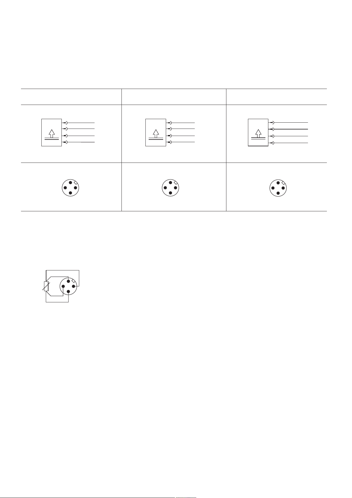
6 Anschluss
6.1 Elektrischer Anschluss
TS…-2UPN… TS…-LUUPN…
1 BN +
TS
3 GND
3 BU
2 WH out 2
4 BK out 1
2 out 2
1 in
4 out 1
6.2 Fühleranschluss
1
2
An die Temperatursensoren TS400/500 können
handelsübliche Pt100-Fühler in 2- oder 4-Leiter-
3 GND
2 V
A
4 out 1
1 in
TS…-LI2UPN…
1 BN +
PS
3 GND
3 BU
2 WH out 2 / I
4 BK out 1
2 out 2 /
4 out 1
1 in
I
A
A
3
4
Technik angeschlossen werden. Bei Fühlern in
2-Leiter-Technik müssen die beiden notwendigen
Brücken im M12-Stecker gelegt werden.
Die Verbindung erfolgt über eine Standard-M12Kupplung.
Im TURCK-Standardprogramm fi nden Sie eine
Vielzahl von Fühlern in 4-Leiter-Technik für Ihre
Applikation.
6 /0208 Hans Turck GmbH & Co.KG • D–45466 Mülheim an der Ruhr
•
www.turck.com
Page 11
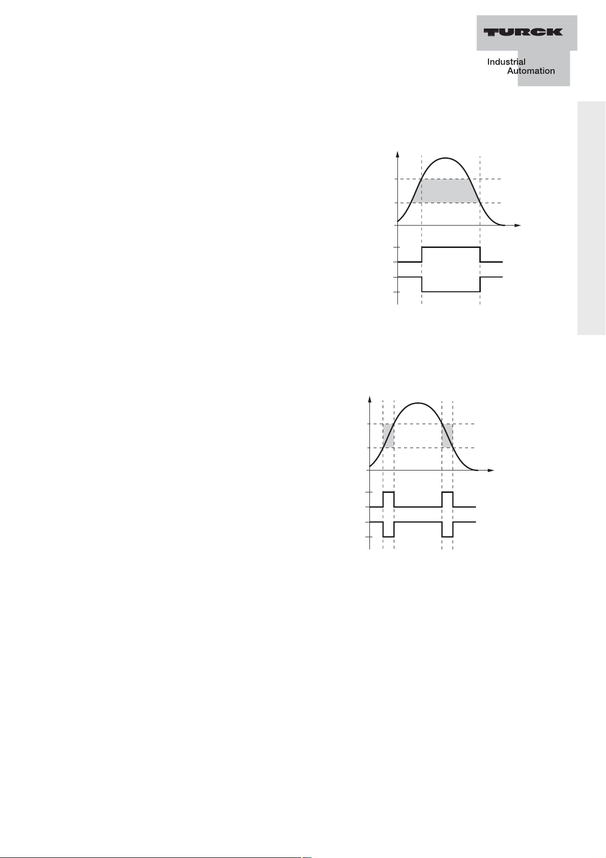
7 Beschreibung der Schaltfunktionen
Hysterese
hysteresis
hystérésis
T
SP
1
rP
t
0
1
0
Hno
Hnc
T
SP
1
rP
t
0
1
0
Fno
Fnc
Gutbereich
acceptable range
plage acceptable
Hysterese:
Diese Funktion realisiert einen stabilen
Schaltzustand, unabhängig von systembedingten Temperaturschwankungen
um den eingestellten Sollwert.
Der Schaltbereich wird vom Anwender
über einen Schaltpunkt (SP) und einen
Rückschaltpunkt (rP) festgelegt.
Fenster:
Temperatursensor-Serie TS400.../TS500...
Diese Funktion realisiert einen Bereich,
in dem der Schalter einen defi nierten
Schaltzustand annimmt.
Der Schaltbereich wird vom Anwender
über eine obere Fenstergrenze (SP)
und eine untere Fenstergrenze (rP)
festgelegt.
Die Mindesthysterese zwischen SP und rP beträgt 0,2 K.
Befi ndet sich die Temperatur unterhalb oder oberhalb der anwenderseitig defi nierten Grenzen, beginnt die Anzeige zu blinken. Ist die
Temperatur 0,3 % außerhalb der spezifi erten Messspanne, erscheint
am unteren Ende der Spanne im Display die Anzeige UL und am
oberen Ende der Spanne die Anzeige OL. Im Falle eines Fühlerdefektes
(Kurzschluss oder Drahtbruch) zeigt das Display Err an.
Hans Turck GmbH & Co.KG • D–45466 Mülheim an der Ruhr
•
www.turck.com 7 /0208
Page 12

Temperatursensor Serie TS...
8 Betriebsarten
Run-Modus – Normalbetrieb
Der Sensor erfasst die Temperatur und zeigt das gewünschte Schaltoder Analogverhalten entsprechend der werkseitig oder kundenspezifi sch eingestellten Parameter. Im Display erscheint die Temperatur, die
gewählte Einheit und der Zustand der vorhandenen Schaltausgänge.
Menü-Modus – Parameter und die zugehörigen Werte
Nach Betätigen der Mode-Taste springt das Display in den MenüModus. Hier können alle Parameter und ihre zugehörigen Werte ausgelesen werden. Durch kurzes Drücken der Set-Taste werden die Werte
angezeigt, die sich hinter einem Parameter verbergen. Die einstellbaren
Möglichkeiten entnehmen Sie bitte der unter Abschnitt 10 angegebenen Tabelle.
Programmier-Modus – Einstellen der Parameterwerte
Über den Menü-Modus gelangt man in den Programmier-Modus. Hier
können alle einstellbaren Parameterwerte verändert werden. Wie im
Menü-Modus beschrieben, kann man sich durch kurzes Drücken der
Set-Taste den Wert anzeigen lassen, der sich hinter einem Parameter
verbirgt. Um diesen Wert zu verändern, hält man die Set-Taste so lange
gedrückt, bis die Anzeige nicht mehr blinkt. Jetzt kann man über die
Tasten „Set” und „Mode” den Wert neu einstellen. Im ProgrammierModus können die Mode- und die Set-Taste zusätzlich als Up- und
Down-Taste benutzt werden. Die einstellbaren Möglichkeiten entnehmen
Sie bitte der unter Abschnitt 10 angegebenen Tabelle.
8 /0208 Hans Turck GmbH & Co.KG • D–45466 Mülheim an der Ruhr
•
www.turck.com
Page 13
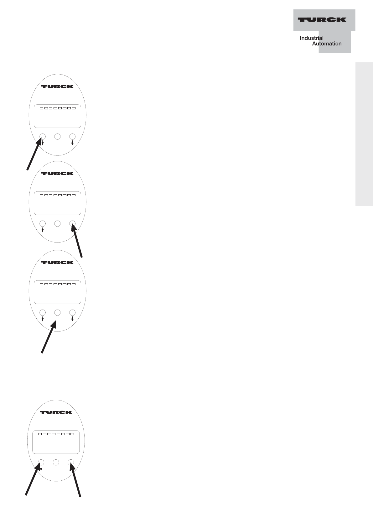
9 Programmierung
9.1 Anzeigen der Parameterwerte und
Programmierung
°C°FK
Ohm
Out 1
Out 2
Drücken Sie die Mode-Taste. In Display erschein nun
Mode Set
Enter
°C°FK
Ohm
Out 2
Mode Set
Enter
°C°FK
Ohm
Out 2
Mode Set
Enter
der Parameter „Uni“. (Sollte im Display die Anzeige
„Loc“ erscheinen, muss der Sensor entsperrt werden.
Beachten Sie bitte hierzu die Informationen unter 9.2).
Sie können sich nun die Einstellung des Parameters
„Uni“ anschauen (siehe unten) oder die weiteren Para-
meter anwählen. Zum Anwählen der weiteren Parameter
Out 1
drücken Sie mehrmals die Mode-Taste.
Um den unter einem Parameter eingestellten Wert
anzeigen zu lassen, drücken Sie kurz die Taste „Set“.
Wenn Sie diesen Wert verändern wollen, drücken Sie die
Taste „Set“ und halten Sie diese 5 s lang gedrückt, bis
Out 1
der angezeigte Wert nicht mehr blinkt. Mit den Tasten
und können Sie den Wert nun verändern.
Drücken Sie die versenkte Taste „Enter“ um den
veränderten Wert zu speichern.
Temperatursensor-Serie TS400.../TS500...
Die neue Einstellung ist damit aktiviert.
9.2 Sperren/Entsperren
Der Zugang zum Menü- und Programmiermodus
kann bei diesem Sensor gesperrt werden.
Zum Sperren betätigen Sie im RUN-Modus die Tasten
°C°FK
Ohm
Out 1
Out 2
„Mode” und „Set” zur gleichen Zeit und halten Sie diese
so lange gedrückt, bis in der Anzeige Loc erscheint.
Mode Set
Enter
Zum Entsperren drücken Sie im RUN-Modus erneut die
Taste „Mode” und „Set” zur gleichen Zeit und halten Sie
diese so lange gedrückt, bis in der Anzeige uLoc
erscheint.
Hans Turck GmbH & Co.KG • D–45466 Mülheim an der Ruhr
•
www.turck.com 9 /0208
Page 14

Temperatursensor Serie TS...
10 Einstellbare Parameter und ihre Bedeutung
10.1 Standardparameter
Parameter Erläuterung Optionen Funktion
Loc Sperrung des Programmiermenü ist
Programmiermenüs komplett gesperrt
uLoc Entsperrung des Programmiermenü ist
Programmiermenüs frei geschaltet
(Auslieferungszustand)
Uni Anzeigeeinheit °C LED grün
°F LED grün
K LED grün
Ohm LED grün
ou1 Funktion von Hno1 Hysteresefunktion
Ausgang 1 (N/O = Schließer)
Hnc1 Hysteresefunktion
(N/C = Öffner)
Fno1 Fensterfunktion
(N/O = Schließer)
Fnc1 Fensterfunktion
(N/C = Öffner)
SP1 Schaltpunkt 1 Oberer Grenzwert, an
dem der Ausgang 1
seinen Schaltzustand
ändert
rP1 Rückschaltpunkt 1 Unterer Grenzwert, an
dem der Ausgang 1
seinen Schaltzustand
ändert
10 /0208 Hans Turck GmbH & Co.KG • D–45466 Mülheim an der Ruhr
•
www.turck.com
Page 15

10.1 Standardparameter – Fortsetzung
Parameter Erläuterung Optionen Funktion
ou2 Funktion von Hno2 Hysteresefunktion
Ausgang 2 (N/O = Schließer)
Hnc2 Hysteresefunktion
(N/C = Öffner)
Fno2 Fensterfunktion
(N/O = Schließer)
Fnc2 Fensterfunktion
(N/C = Öffner)
Analogausgang (I) 4-20 ansteigende Gerade
Nur bei Typ: 0-20
TS...-LI... 20-4 abfallende Gerade
20-0
Analogausgang (V) 0-10 ansteigende Gerade
Nur bei Typ: 0-5
TS...-LU... 1-6
10-0 abfallende Gerade
5-0
6-1
SP2 Schaltpunkt 2
Nur bei Typ:
Oberer Grenzwert, an
dem der Ausgang 2
TS...-LI2UPN8X seinen Schaltzustand
TS...-2UP8NX ändert
Temperatursensor-Serie TS400.../TS500...
rP2 Rückschaltpunkt 2 Unterer Grenzwert, an
Nur bei Typ: dem der Ausgang 2
TS...-LI2UPN8X seinen Schaltzustand
TS...-2UP8NX ändert
ASP Startpunkt des Temperatur an der der
Analogsignals Analogausgang seinen
Nur bei Typ: Startpunkt hat
TS…-LI…,
TS…-LU…
Hans Turck GmbH & Co.KG • D–45466 Mülheim an der Ruhr
•
www.turck.com 11 /0208
Page 16

Temperatursensor Serie TS...
10.1 Standardparameter – Fortsetzung
Parameter Erläuterung Optionen Funktion
AEP Endpunkt des Temperatur an dem der
Analogausgangs Analogausgang seinen
Nur bei Typ: Endpunkt hat
TS…-LI…,
TS…-LU…
EF Untermenu für Wenn auf dem Display
zusätzliche der Parameter EF
Einstell- erscheint, können Sie
möglichkeiten durch das Betätigen der
Set-Taste verschiedene
Zusatzeinstellungen in
einem Untermenü
vornehmen. Siehe 10.2
12 /0208 Hans Turck GmbH & Co.KG • D–45466 Mülheim an der Ruhr
•
www.turck.com
Page 17

10.2 Zusätzliche Parameter (Untermenü EF)
Parameter Erläuterung Optionen Funktion
Hi Maximalwert-
Höchste Temperatur wird
Speicher im Permanentspeicher
abgelegt
Lo Minimalwert- Niedrigste Temperatur
Speicher wird im Permanent-
speicher abgelegt
CoF Offset Justage Bedingt durch starke
thermische Veränderung
in der Umgebung des
Temperatursensor-Serie TS400.../TS500...
Sensors kann es zu
einer Messwert verschiebung kommen.
Diese Drift lässt sich
korrigieren.
Einstellbereich: -10 bis
+10 % der Messspanne
dS1 Schaltverzögerung 0 / 0,1 ... 50 s in
von SP1 Schritten von 0,1 s
(0 = Verzögerungszeit ist
nicht aktiv)
dr1 Schaltverzögerung 0 / 0,1 ... 50 s in
von rP1 Schritten von 0,1 s
(0 = Verzögerungszeit ist
nicht aktiv)
dS2 Schaltverzögerung 0 / 0,1…50 s in
von SP2 Schritten von 0,1 s
Nur bei Typ: (0 = Verzögerungszeit ist
TS…LI2UPN8X nicht aktiv)
TS…2UPN8X
dr2 Schaltverzögerung 0 / 0,1…50 s in
von rP2 Schritten von 0,1
Nur bei Typ: (0 = Verzögerungszeit ist
TS…LI2UPN8X nicht aktiv)
TS…2UPN8X
Hans Turck GmbH & Co.KG • D–45466 Mülheim an der Ruhr
•
www.turck.com 13 /0208
Page 18

Temperatursensor Serie TS...
10.2 Zusätzliche Parameter (Untermenü EF) – Fortsetzung
Parameter Erläuterung Optionen Funktion
Fou 1 Verhalten des Aus- Fou 1 = on
Ausgang schaltet im
gangs 1 bei Fühler- Fehlerfall ein
defekt (Drahtbruch- Fou 1 = oFF Ausgang schaltet im
oder Kurzschluss) Fehlerfall aus
Fou 2 Verhalten des Aus- Fou 2 = on
Ausgang schaltet im
gangs 2 bei Fühler- Fehlerfall ein
defekt (Drahtbruch- Fou 2 = oFF Ausgang schaltet im
oder Kurzschluss) Fehlerfall aus
Fou 2 = on Ausgangssignal bei
10,5 V/5,5 V/6,5 V
Fou 2 = oFF Ausgangssignal bei 0 V
Fou 2 = on Ausgangssignal bei
22,5 mA
Fou 2 = oFF Ausgangssignal bei
0/3,5 mA
P-n Verhalten des npn n-schaltend
Schaltausgangs pnp p-schaltend
diS Messwert- 50 50 ms update
aktualisierung 200 200 ms update
im Display 600 600 ms update
r50 50 ms update/ Display
um 180° gedreht
r200 200 ms update/ Display
um 180° gedreht
r600 600 ms update/ Display
um 180° gedreht
OFF Display wird ausge schaltet und durch
Drücken der Mode- oder
Set-Taste für 10 s aktivi ert
14 /0208 Hans Turck GmbH & Co.KG • D–45466 Mülheim an der Ruhr
•
www.turck.com
Page 19

10.2 Zusätzliche Parameter (Untermenü EF) – Fortsetzung
Parameter Erläuterung Optionen Funktion
rES Rücksetzen in den
Auslieferzustand
SOF Software-Version
Temperatursensor-Serie TS400.../TS500...
Hans Turck GmbH & Co.KG • D–45466 Mülheim an der Ruhr
•
www.turck.com 15 /0208
Page 20
Temperatursensor Serie TS...
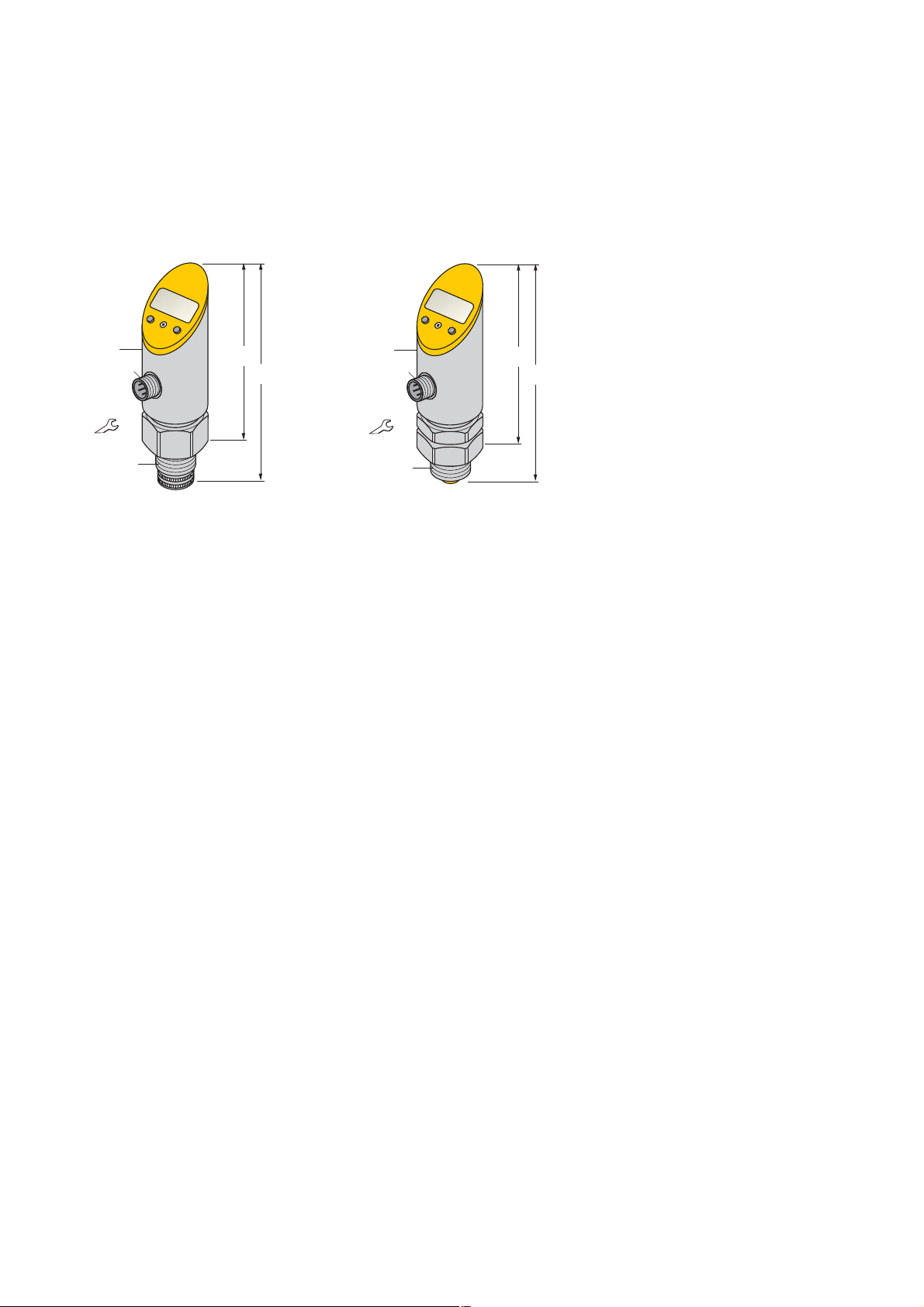
11 Maßzeichnungen
TS400-... TS500-...
ø 34
M12 x 1
G1/2"
30
90
110
ø 34
M12 x 1
30
G1/2"
95
110
16 /0208 Hans Turck GmbH & Co.KG • D–45466 Mülheim an der Ruhr
•
www.turck.com
Page 21
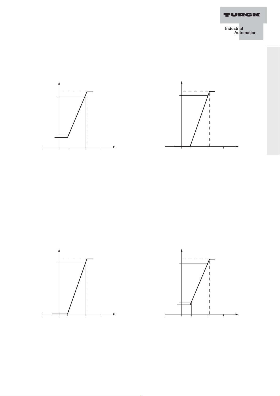
12 Kennlinien der Analogausgänge
Stromausgang
4…20 mA 0…20 mA
I [mA
50
20
]
4
0
ASP
AEP T
MEW
50
I [mA
20
]
0
ASP
AEP
MEW
T
Im defi nierten Messbereich zwischen ASP (analoger Startpunkt) und
AEP (analoger Endpunkt) liegt das Ausgangssignal zwischen 4 und
20 mA oder alternativ zwischen 0 und 20 mA. Im Auslieferungszustand
liegt der Messbereich zwischen 0 und dem MEW (Messbereichsendwert) und das Ausgangssignal zwischen 4 mA (ASP) und 20 mA (AEP).
Temperatursensor-Serie TS400.../TS500...
Spannungsausgang
0…5 V oder 0…10 V 1…6 V
U [V
5 bzw.10
50
]
0
ASP
AEP
MEW
T
50
U [V
]
6
1
0
ASP
AEP T
MEW
Im defi nierten Messbereich zwischen ASP (analoger Startpunkt) und
AEP (analoger Endpunkt) liegt das Ausgangssignal zwischen 0 und 10
V oder alternativ zwischen 0 und 5 V oder 1…6 V. Im Auslieferungszustand liegt der Messbereich zwischen 0 und dem MEW (Messbereichsendwert) und das Ausgangssignal zwischen 0 V (ASP) und 10 V (AEP).
Hans Turck GmbH & Co.KG • D–45466 Mülheim an der Ruhr
•
www.turck.com 17 /0208
Page 22

Temperatursensor Serie TS...
13 Technische Daten
Typenbezeichnung TS400… TS-500…
Temperaturbereich -50…+500 °C
Ausgänge 2 Schalter oder
1 Schalter und
ein Analogausgang
(frei konfi gurierbar)
Analoger Stromausgang (0)4…20 mA
Analoger Spannungs- 0…10 V
ausgang 0…5 V
1…6 V
Genauigkeit Schaltpunkt 0,2 K
Kennlinienabweichung
Nichtlinearität, Hysterese
und Wiederholbarkeit 0,2 K
Schaltpunktabstand 0,2 K
Schaltpunkte -49,8...+500 °C
Rückschaltpunkte -50...+499,8 °C
Art der Anzeige 4-stellige
7-Segment-Anzeige
Anzeige drehbar 180 °
Anzahl Programmiertaster 3
Gehäusewerkstoff Edelstahl 1.4404 (AISI 316L)
Sensorkörper ausrichtbar nein 340°
Medientemperatur je nach Fühler und Art des Einbaus
-50...+500 °C
Umgebungstemperatur -40...+80 °C
Lagertemperatur -40...+80 °C
18 /0208 Hans Turck GmbH & Co.KG • D–45466 Mülheim an der Ruhr
•
www.turck.com
Page 23

Typenbezeichnung TS400… TS-500…
Betriebsspannung 15…30 VDC bei
2 Schaltausgänge
18…30 VDC bei
Analogausgang
SELF, PELV nach EN 50178
Leerlaufstrom I
≤ 50 mA
0
Schaltfrequenz ≤ 180 Hz
Ausgangsfunktion 2 PNP/NPN,
Öffner/Schließer, progr.
Spannungsfall bei I
≤ 2 V
e
Temperatursensor-Serie TS400.../TS500...
Kurzschlussschutz ja
Verpolungsschutz ja
Bemessungsbetriebsstrom 0,2 A
Schutzart IP67
Schutzklasse III
EMV
EN 61000-4-2 ESD: 4 KV CD/8 KV AD
EN 61000-4-3 HF gestrahlt: 15 V/m
EN 61000-4-4 Burst: 2 KV
EN 61000-4-5 Surge: 500 V, 12 Ω
EN 61000-4-6 HF Leitungsgeb.: 10 V
Überwurfmutter mit SW 30
Anzugsdrehmoment max. 35 Nm
Vibrationsfestigkeit 20 g (10…2000 Hz)
gemäß IEC 68-2-6
Schockfestigkeit 50 x g (11 ms)
gem. IEC 68-2-27
Elektrischer Anschluss Stecker M12 x 1
Fühleranschluss Kupplung M12 x 1
Hans Turck GmbH & Co.KG • D–45466 Mülheim an der Ruhr
•
www.turck.com 19 /0208
Page 24

Temperatursensor Serie TS...
20 /0208 Hans Turck GmbH & Co.KG • D–45466 Mülheim an der Ruhr
•
www.turck.com
Page 25

Table of Contents
Chapter Contents Page
1 Introduction 2
2 Safety information 2
2.1 General information 2
2.2 Correct usage to the intended purpose 2
2.3 Qualifi ed staff 3
2.4 Remaining hazards 3
2.5 CE conformity 3
3 Description 4
4 Installation and set-up instructions 5
5 Mounting 5
6 Connections 6
6.1 Electrical connection 6
6.2 Sensor connection 6
7 Description of the switching functions 7
8 Operating modes 8
9 Programming 9
9.1 Indication of parameter values 9
9.2 Locking/Unlocking 9
10 Adjustable parameters 10
10.1 Standard parameters 10
Temperature Sensor Series TS400.../TS500...
10.2 Additional parameters (sub-menu EF) 13
11 Dimension drawings 17
12 Typical curve of analogue output 16
13 Technical data 18
Hans Turck GmbH & Co.KG • D–45466 Mülheim an der Ruhr
•
www.turck.com 1 /0208
Page 26

Temperature Sensor Series TS...
1 Introduction
Dear Customer!
We would like to thank you for opting for a product from our company
and would like to confi rm you in your decision.
The sensors can be programmed on-site for various different applications.
In order to be able to fully utilise the wide range of functions, we kindly
request you to observe the following issues:
Any person entrusted with the set-up or operation of the device, must
have read and understood this operation manual, in particular all safety
notes.
2 Safety information
2.1 General information
In order to ensure safe operation, the device may only be operated in
accordance to the specifi cations stated in this operation manual. Further it is required to observe all legal and safety regulations applicable to
the specifi c application.
This also applies to the usage of accessories.
2.2 Correct usage to the intended purpose
These devices are designed for indication and monitoring of process
variables. All other forms of usage do not comply with the intended purpose.
These sensors may not be used as the sole means for prevention of
dangerous machine and system conditions. Machines and systems
must be constructed in such a way, that faulty states cannot lead to a
dangerous situation for the operating staff (e.g. due to independent limit
switches, mechanical interlocking devices, etc.).
2 /0208 Hans Turck GmbH & Co.KG • D–45466 Mülheim an der Ruhr
•
www.turck.com
Page 27

2.3 Qualifi ed staff
The devices may only be installed, connected, set-up and operated by
qualifi ed staff and in compliance with the technical specifi cations.
Qualifi ed staff is defi ned as persons, who are familiar with set-up,
mounting, start-up and operation of this device and who possess a
recognized degree or certifi cate of appropriate professional training.
2.4 Remaining hazards
These sensors employ state-of-the-art technology and are safe to operate. However, if they are installed and operated by unqualifi ed staff, an
element of risk remains.
In this manual the remaining risks are marked by the following symbol:
This symbol is posted where there is a risk of serious
!
injury or death or the damage of material and property,
if the warning is ignored
2.5 CE conformity
The device accords to EN 61326 and may only be used in industrial
environments.
The conformity declaration can be downloaded from the Internet under
www.turck.com
Temperature Sensor Series TS400.../TS500...
Hans Turck GmbH & Co.KG • D–45466 Mülheim an der Ruhr
•
www.turck.com 3 /0208
Page 28

Temperature Sensor Series TS...
3 Description
Devices of the pressure series TS... are intelligent pressure sensors
which have been specially developed for use in machine engineering.
The following 3 output variants are available:
…2UPN8X 2 switching outputs (pnp/npn)
…LI2UPN8X 1 output switching (pnp/npn) and 1 output
switching (pnp/npn) or analog output (current)
…LUUPN8X 1 output switching (pnp/npn) and 1 analog output
(voltage)
The measured temperature can be displayed in °C, °F, K and Ohm.
The analogue signal can be offset in a range from -50 °C to 500 °C. Min.
and max value are stored and can be read in the programming mode.
The housing TS500... can be aligned (340°) and fi xed after mounting.
4 /0208 Hans Turck GmbH & Co.KG • D–45466 Mülheim an der Ruhr
•
www.turck.com
Page 29

4 Installation and set-up instructions
1. Even though the device is excellently protected against electro-
magnetic interference, installation and cabling must be carried out
correctly to ensure interference immunity.
2. Never route signal and control cables together with the mains cable
or feeder cables of motors, cylinder coils, rectifi ers etc. The cables
must be routed in conductive and grounded cable conduits. This
applies especially to long-distance cables, or environments in which
the cables are exposed to strong radio waves from broadcasting
stations.
3. Signal lines should be installed in mounting cabinets and as far
away as possible from contactors, control relays, transformers and
other sources of interference.
5 Mounting
!
• Signifi cant thermal changes in the environment of the processor unit
can lead to a measured value offset. This kind of drift can be
corrected (see chapter 10.2, parameter CoF).
• The read direction of the on-site display can be rotated via
software by 180° (see chapter 10.2, parameter diS).
• In the pressureless state, the housing of the TS500... series can be
rotated by 340° after mounting.
Temperature Sensor Series TS400.../TS500...
Hans Turck GmbH & Co.KG • D–45466 Mülheim an der Ruhr
•
www.turck.com 5 /0208
Page 30

Temperature Sensor Series TS...
TS
2 WH V
A
4 BK out
1 BN +
3 BU
6. Connection
6.1 Electrical connection
TS…-2UPN… TS…-LUUPN…
1 BN +
TS
3 GND
3 BU
2 WH out 2
4 BK out 1
2 out 2
1 in
4 out 1
6.2 Sensor connection
1
2
Conventional commercially available Pt100 sensors
can be connected to the temperature sensors
3 GND
2 V
A
4 out 1
1 in
TS…-LI2UPN…
1 BN +
PS
3 GND
3 BU
2 WH out 2 / I
4 BK out 1
2 out 2 /
4 out 1
1 in
I
A
A
3
4
TS400/500 using 2 or 4-wire technology. On sensors
with 2-wire technology both the necessary jumpers
must be applied in the M12 connector. The connection is made using a standard M12 female connector.
The TURCK standard product range includes an
entire range of 4-wire technology sensors for your
application.
6 /0208 Hans Turck GmbH & Co.KG • D–45466 Mülheim an der Ruhr
•
www.turck.com
Page 31

7 Description of the various switching functions
Hysterese
hysteresis
hystérésis
T
SP
1
rP
t
0
1
0
Hno
Hnc
T
SP
1
rP
t
0
1
0
Fno
Fnc
Gutbereich
acceptable range
plage acceptable
Hysteresis:
This function ensures a stable switching
status, independent of the system-inherent temperature fl uctuations and the
adjusted set point.
The switching range is defi ned by the
user via a switching point (SP) and a
release position (rP).
Window:
With this function a range is determined
in which the switch assumes a defi ned
switching status.
The switching range is defi ned by the
user via an upper window limt (SP) and
a low window limit (rP).
The minimum hysteresis between SP and rP is approx. 0.2 K.
If the applied temperture is above or below the customer defi ned limits,
the display starts fl ashing. If the applied temperature is 0.3 % outside
the specifi ed measuring range, the display will indicate UL at the lower
Temperature Sensor Series TS400.../TS500...
range limit and OL at the upper range limit. The display will indicate Err
it the probe is faulty (short-circuit or wire break).
Hans Turck GmbH & Co.KG • D–45466 Mülheim an der Ruhr
•
www.turck.com 7 /0208
Page 32

Temperature Sensor Series TS...
8 Operating modes
Run mode – Standard operation
The sensor detects the temperature and acts in accordance to the required switching or analogue performance, meeting the ex-factory or
customer-specifi c parameters. The display indicates the temperature,
the selected unit of pressure and the status of the switching outputs.
Menu mode - Parameters and associated values
Upon a push of the mode button, the display assumes the menu mode.
In this mode all parameters and the associated values can be read. To
view the values associated with a parameter, simply press the "Set" button for a short moment. The adjustment options can be taken from the
table under point 10.
Programming mode - Adjustment of the parameter values
The programming mode is accessed via the menu mode. In this mode,
all adjustable parameters can be modifi ed. As described under the
menu mode, it is possible to view the value programmed for a certain parameter via a short press of the "Set" button. In order to modify
this value, the "Set" button must be pressed and held until the display
stops fl ashing. Now it is possible to re-adjust the value via the "Set" and
"Mode" button. In the programming mode, the "Set" and "Mode" button
can also be used as an "UP" and "Down" button. The adjustment options can be taken from the table under point 10.
8 /0208 Hans Turck GmbH & Co.KG • D–45466 Mülheim an der Ruhr
•
www.turck.com
Page 33

9 Programming
9.1 Indication of the parameter values and
programming
°C°FK
Ohm
Out 1
Out 2
Press the "Mode" button. The display now shows the
Mode Set
Enter
°C°FK
Ohm
Out 2
Mode Set
Enter
°C°FK
Ohm
Out 2
Mode Set
parameter ”Uni”. (Should ”Loc” be displayed, the sen sor must be enabled. For this please refer to the infor
mation provided in paragraph 9.2). You can now view the
setting of the parameter ”Uni” (see below) or select
further parameters. To select other parameters, press
the ”Mode” button several times. To view the actual
Out 1
parameter value, simply press the ”Set” button for a
short moment.
If you want to alter this value, please press the "Set"
button and hold it for 5 s until the shown value stops
fl ashing. Via the and buttons you can now change
the value.
Out 1
Then press the recessed ”Enter” button to save the
changed value.
Enter
The new setting is consequently activated.
9.2 Locking/Unlocking (disabling/enabling)
This sensor permits inhibiting access to the menu and
programming mode.
°C°FK
Ohm
Out 1
Out 2
To inhibit access, call up the RUN mode, press and hold
the ”Mode” and ”Set” buttons simultaneously until the
Mode Set
Enter
display indicates Loc.
To enable access, call up the RUN mode, press and
hold the "Mode" and "Set" buttons simultaneously until
the display indicates uLoc.
Temperature Sensor Series TS400.../TS500...
Hans Turck GmbH & Co.KG • D–45466 Mülheim an der Ruhr
•
www.turck.com 9 /0208
Page 34

Temperature Sensor Series TS...
10 Adjustable parameters and their meaning
10.1 Standard parameters
Parameter Explanation Options Function
Loc Disabling the Programming mode
programming mode fully disabled/locked
uLoc Enabling the Programming mode
programming mode enabled/unlocked
(default/ex factory)
Uni Display unit °C LED green
°F LED green
K LED green
Ohm LED green
ou1 Function of Hno1 Hysteresis function
output 1 (N/O = normally open)
Hnc1 Hysteresis function
(N/C = normally closed)
Fno1 Window function
(N/O = normally open)
Fnc1 Window function
(N/C = Öffner)
SP1 Switch point 1 Upper limit value at
which output 1
changes its switching
status
rP1 Release point 1 Lower limit value at
which output 1
changes its switching
status
10 /0208 Hans Turck GmbH & Co.KG • D–45466 Mülheim an der Ruhr
•
www.turck.com
Page 35

10.1 Standard parameters – Continuation
Parameter Explanation Options Function
ou2 Function of Hno2 Hysteresis function
output 2 (N/O = normally open)
Hnc2 Hysteresis function
(N/C = normally closed)
Fno2 Window function
(N/O =normaly open)
Fnc2 Window function
(N/C = normally closed)
Analogue output (I) 4-20 rising straight line
only type: 0-20
TS...-LI... 20-4 falling straight line
20-0
Analogue output (V) 0-10 rising straight line
only type: 0-5
TS...-LU... 1-6
10-0 falling straight line
5-0
6-1
SP2 Switch point 2
only type:
Upper limit value at
which output 2
TS...-LI2UPN8X changes its switching
TS...-2UPN8X status
rP2 Release point 2 Lower limit value at
only type: which output 2
TS...-LI2UPN8X changes its switching
TS...-2UPN8X status
Temperature Sensor Series TS400.../TS500...
ASP Starting point of Temperature at which
the analogue output the analogue output has
only type: its starting point
TS…-LI…,
TS…-LU…
Hans Turck GmbH & Co.KG • D–45466 Mülheim an der Ruhr
•
www.turck.com 11 /0208
Page 36

Temperature Sensor Series TS...
10.1 Standard parameters – Continuation
Parameter Explanation Options Function
AEP End point of the Temperature at
analogue output which the analogue
only type: output has its end point
TS…-LI…,
TS…-LU…
EF Extra menu for If the display shows
additional the parameter EF,
settings the user can adjust
various additional
parameters in the sub menu using the "Set"
button (see 10.2).
12 /0208 Hans Turck GmbH & Co.KG • D–45466 Mülheim an der Ruhr
•
www.turck.com
Page 37

10.2 Additional parameters (sub-menu EF)
Parameter Explanation Options Function
Hi Max. value The highest temperature
is stored in the
non-volatile memory.
Lo Min. value The lowest temperature
is stored in the
non-volatile memory.
CoF Offset correction Signifi cant thermal
changes in the sensor
environment can lead to
a measured value offset.
This drift can be
corrected.
Adjustment range:
-10 to +10 % of the
measuring span
dS1 Switching delay 0 / 0.1 ... 50 s in
of SP1 increments of 0.1 s
(0 = delay time is
not active)
dr1 Switching delay 0 / 0.1 ... 50 s in
of rP1 increments of 0.1 s
(0 = delay time is
not active)
dS2 Switching delay 0 / 0.1…50 s in
of SP2 increments of 0.1 s
only type: (0 = switching delay is
TS…LI2UPN8X not active)
TS…2UPN8X
Temperature Sensor Series TS400.../TS500...
dr2 Switching delay 0 / 0.1…50 s in
of rP2 increments of 0.1 s
only type: (0 = switching delay is
TS…LI2UPN8X not active)
TS…2UPN8X
Hans Turck GmbH & Co.KG • D–45466 Mülheim an der Ruhr
•
www.turck.com 13 /0208
Page 38

Temperature Sensor Series TS...
10.2 Additional parameters (sub-menu EF) – Continuation
Parameter Explanation Options Function
Fou 1 Performance of Fou 1 = on Output switches on
output 1 with probe with fault
fault (wire break Fou 1 = oFF Output switches off
or short-circuit) with fault
Fou 2 Performance of Fou 2 = on Output switches on
output 2 with probe with fault
fault (wire break Fou 2 = oFF Output switches off
or short-circuit) with fault
Fou 2 = on Output signal at
10.5 V/5.5 V/6.5 V
Fou 2 = oFF Output signal at 0 V
Fou 2 = on Output signal at
22.5 mA
Fou 2 = oFF Output signal at
0/3.5 mA
P-n Switching npn NPN
output mode pnp PNP
only type:
diS Update of 50 50 ms update
measuring value 200 200 ms update
on display 600 600 ms update
r50 50 ms update/ display
rotated by 180°
r200 200 ms update/ display
rotated by 180°
r600 600 ms update/ display
rotated by 180°
OFF Display is turned off
and activated for 10 s
by pressing the "Mode"
or "Set" button
14 /0208 Hans Turck GmbH & Co.KG • D–45466 Mülheim an der Ruhr
•
www.turck.com
Page 39

10.2 Additional parameters (sub-menu EF) – Continuation
Parameter Explanation Options Function
rES Reset to the
default state
SOF Software version
Hans Turck GmbH & Co.KG • D–45466 Mülheim an der Ruhr
•
www.turck.com 15 /0208
Temperature Sensor Series TS400.../TS500...
Page 40

Temperature Sensor Series TS...
11 Dimension drawings
TS400-... TS500-...
ø 34
M12 x 1
30
G1/2"
90
110
ø 34
M12 x 1
30
G1/2"
95
110
16 /0208 Hans Turck GmbH & Co.KG • D–45466 Mülheim an der Ruhr
•
www.turck.com
Page 41

12 Typical curves of the analogue outputs
Current output
4…20 mA 0…20 mA
I [mA
]
I [mA
]
50
20
4
0
ASP
AEP T
MEW
50
20
0
ASP
AEP
MEW
T
Within the defi ned measuring range between ASP (analogue start point)
and AEP (analogue end point), the output signal is between 4 and
20 mA or alternatively between 0 and 20 mA. The factory-set measuring
range is between 0 and MEW (measuring range end value) and the default output signal is between 4 mA (ASP) and 20 mA (AEP).
Voltage output
0…5 V or 0…10 V 1…6 V
U [V
5 bzw.10
50
]
0
ASP
AEP
MEW
T
50
U [V
]
6
1
0
ASP
AEP T
MEW
Within the defi ned measuring range between ASP (analogue start point)
and AEP (analogue end point), the output signal is between 0 and 10 V
or
alternatively between 0 and 5 or 1...6 V. The factory-set measuring range
is between 0 and MEW (measuring range end value) and the default output signal is between 0 V (ASP) and 10 V (AEP).
Temperature Sensor Series TS400.../TS500...
Hans Turck GmbH & Co.KG • D–45466 Mülheim an der Ruhr
•
www.turck.com 17 /0208
Page 42

Temperature Sensor Series TS...
13 Technical Data
Type TS400… TS-500…
Temperature range -50...+500 °C
Outputs 2 switching outputs or
1 switching and 1
analogue output
(freely confi gurable)
Analogue current output (0)4...20 mA
Analogue voltage output 0...5 V
0...10 V
1...6 V
Switch point accuracy 0.2 K
Deviation from typ. curve
Non-linearity, hysteresis,
repeat accuracy 0.2 K
Switch point clearance 0.2 K
Switch points -49.8...+500 °C
Release positions -50...+499.8 °C
Type of display 4-digit 7-segment
display
Display, rotatable 180 °
No. of progr. buttons 3
Housing material Stainless steel 1.4404
(AISI 316L)
Sensor body, adjustable no 340°
Medium temperature depending on (applied) probe and
mounting modalities
-50...+500 °C
Ambient temperature -40...+80 °C
18 /0208 Hans Turck GmbH & Co.KG • D–45466 Mülheim an der Ruhr
•
www.turck.com
Page 43

Storage temperature -40...+80 °C
Type TS400… TS-500…
Operating voltage 15... 30 VDC with
2 switching outputs
18...30 VDC with
analogue output
SELV, PELF to EN 50178
No-load current I
≤ 50 mA
0
Switching frequency ≤ 180 Hz
Output function 2 PNP/NPN,
N.C/N.O., progr.
Voltage drop at I
≤ 2 V
e
Short-circuit protection yes
Rev. polarity protection yes
Rated operating current 0.2 A
Degree of protection IP67
Protection class III
EMC
EN 61000-4-2 ESD: 4 KV CD/ 8 KV AD
EN 61000-4-3 HF irradiated: 15 V/m
EN 61000-4-4 Burst: 2 KV
EN 61000-4-5 Surge: 500 V, 12 Ω
EN 61000-4-6 HF conducted: 10 V
Temperature Sensor Series TS400.../TS500...
Coupling nut SW 30
with fi xing torque max. 35 Nm
diaphragm fi tting no
Vibration resistance 20 g (10…2000 Hz)
acc. to IEC 68-2-6
Shock resistance 50 x g (11 ms)
to IEC 68-2-27
Electrical connection connector M12 x 1
Probe connection female connector M12 x 1
Hans Turck GmbH & Co.KG • D–45466 Mülheim an der Ruhr
•
www.turck.com 19 /0208
Page 44

Temperature Sensor Series TS...
20 /0208 Hans Turck GmbH & Co.KG • D–45466 Mülheim an der Ruhr
•
www.turck.com
Page 45

Table des matières
Chapitre Contenu Page
1 Préface 2
2 Conseils de sécurité 2
2.1 Généralités 2
2.2 Utilisation réglementaire 2
2.3 Personnel qualifi é 3
2.4 Dangers éventuels en cas d’utilisation non
réglementaire 3
2.5 Conformité CE 3
3 Description 4
4 Mise en service 5
5 Montage 5
6 Raccordement 6
6.1 Raccordement électrique 6
6.2 Connexion sondes 6
7 Description des variantes de fonctions
de commutation 7
8 Modes de fonctionnement 8
9 Programmation 9
9.1 Visualisation des paramètres 9
9.2 Bloquer/Débloquer 9
10 Paramètres réglables 10
10.1 Paramètres standard 10
10.2 Paramètres supplémentaires (sous-menu EF) 13
11 Schémas dimensionnels 16
12 Courbe caractéristique de la sortie analogique 17
13 Données techniques 18
Hans Turck GmbH & Co.KG • D–45466 Mülheim an der Ruhr
•
www.turck.com 1 /0208
Détecteurs de température – série TS400.../TS500...
Page 46

Détecteurs de température – série TS...
1 Préface
Cher client!
Nous vous remercions de votre choix d’utiliser un produit de fabrication
maison et vous en félicitons.
Les détecteurs peuvent être programmés sur le site pour de nombreuses applications différentes. Pour profi ter d’une façon optimale de ses
fonctions multiples, nous vous conseillons de respecter les règles suivantes:
Toute personne chargée de la mise en service ou de l’opération de cet
appareil est tenue d’avoir lu et compris le mode d’emploi et particulièrement les conseils de sécurité!
2 Conseils de sécurité
2.1 Généralités
Pour assurer un fonctionnement fi able, l’appareil doit opérer selon les
spécifi cations reprises dans le mode d’emploi. En plus, il faut respecter
la législation et les mesures de sécurité applicables pour l’application
concernée. Par analogie, cette règle s’applique également aux accessoires.
2.2 Utilisation réglementaire
Les appareils servent à affi cher et surveiller les unités de processus.
Tout autre usage est considéré comme non réglementaire.
Les détecteurs ne peuvent pas être utilisés comme seul moyen pour
éviter des situations dangereuses aux machines et installations. Les machines et installations doivent être conçues de telle façon que des situations dangereuses ne peuvent se présenter et mettre le personnel en
danger (par ex. par des interrupteurs de valeur limite indépendants, des
verrouillages mécaniques, etc.).
2 /0208 Hans Turck GmbH & Co.KG • D–45466 Mülheim an der Ruhr
•
www.turck.com
Page 47

2.3 Personnel qualifi é
Les appareils de cette série de détecteurs ne peuvent être utilisés que
par du personnel qualifi é et uniquement suivant les données techniques.
Par personnel qualifi é on entend les personnes qui connaissent bien
l’arrangement, le montage, la mise en service et le fonctionnement de
cet appareil, et qui disposent d’une qualifi cation appropriée.
2.4 Dangers éventuels en cas d’utilisation non réglementaire
Les détecteurs répondent à la technique actuelle et fonctionnent de
façon fi able. Les appareils peuvent présenter des dangers lorsqu’ils
sont manipulés incorrectement par du personnel non qualifi é.
Le symbole ci-dessous rappel le risque de danger éventuel:
!
Ce symbole rappel le risque de danger corporel ou mortel et/ou
la possibilité de dommages aux biens lorsque les conseils de
sécurité ne sont pas respectés.
2.5 Conformité CE
L’appareil est conforme à la norme EN 61326 et ne peut être utilisé que
dans l’industrie.
La déclaration de conformité peut être obtenue par internet à l'adresse
"www.turck.com".
Hans Turck GmbH & Co.KG • D–45466 Mülheim an der Ruhr
•
www.turck.com 3 /0208
Détecteurs de température – série TS400.../TS500...
Page 48

Détecteurs de température – série TS...
3 Description
Les appareils de la série TS... sont des détecteurs de température intelligents qui ont été conçus spécialement pour les applications de la construction de machines.
3 Variantes de sortie sont disponibles:
…2UPN8X 2 sorties de commutation (pnp/npn)
…LI2UPN8X 1 sortie commutant (pnp/npn) et 1 sortie commutant
(pnp/npn) ou sortie analogique (courant)
…LUUPN8X 1 sortie commutant (pnp/npn) et sortie analogique
(tension)
La température mesurée peut être visualisée en °C, °F, K et ohm.
Le signal analogique se fait déplacer au choix dans la plage -50 °C à
500 °C. La valeur min. et max. sont mémorisées et peuvent être sorties
dans le mode de programmation. Le format TS500... se laisse encore
pivoter (340°) et fi xer après montage.
4 /0208 Hans Turck GmbH & Co.KG • D–45466 Mülheim an der Ruhr
•
www.turck.com
Page 49

4 Conseils d’installation et de mise en service
Bien que l’appareil offre une protection importante contre les interférences électromagnétiques, l’installation et la pose de
câbles doivent être réalisées réglementairement en vue
d’assurer l’immunité aux parasites.
1. Utilisez un câble blindé pour les câbles de signaux et de commande.
Le fi l de raccordement du blindage doit être aussi court que possible.
Le point de raccordement du blindage dépend des conditions de
raccordement qui se présentent.
2. Ne poser jamais les câbles de signaux et de commande ensemble
avec les lignes d’alimentation, les lignes d’alimentation de moteur,
les lignes d’alimentation de bobines cylindriques, les redresseurs,
etc. Les lignes doivent être posées dans des caniveaux électriques
mis à la terre. Ceci vaut surtout en cas de grandes distances de
ligne, ou lorsque les lignes sont soumises à des ondes radioélec triques fortes par des émetteurs de radiodiffusion.
3. Posez les câbles de signaux dans les armoires électriques aussi
éloignés que possible des contacteurs-interrupteurs, des relais de
commande, des transformateurs et d’autres sources de parasites.
5 Montage
!
• Suite à un changement thermique brusque aux environs de l'unité
de traitement, un déplacement des valeurs enregistrées peut se produire. Cette dérive peut être corrigée (voir chapitre 10.2 paramètre
CoF).
• La direction de lecture de l’affi cheur sur le site peut pivoter par
une programmation à 180° (voir chapitre 10.2 paramètre diS).
• Le boîtier du format TS500... se laisse pivoter à 340° après le
montage.
Hans Turck GmbH & Co.KG • D–45466 Mülheim an der Ruhr
•
www.turck.com 5 /0208
Détecteurs de température – série TS400.../TS500...
Page 50

Détecteurs de température – série TS...
TS
2 WH V
A
4 BK out
1 BN +
3 BU
TS
2 WH out 2
4 BK out 1
1 BN +
3 BU
6 Raccordement
6.1 Raccordement électrique
TS…-2UPN… TS…-LUUPN…
2 out 2
3 GND
1 in
4 out 1
6.2 Connexion sondes
1
2
Des sondes Pt100 en technique 2 ou 4 fi ls peuvent
être raccordées aux capteurs de température
3 GND
2 V
A
4 out 1
1 in
TS…-LI2UPN…
1 BN +
PS
3 GND
3 BU
2 WH out 2 / I
4 BK out 1
2 out 2 /
4 out 1
1 in
I
A
A
3
4
TS400/500. En cas de sondes en technique 2 fi ls,
il faut prévoir les deux pontages dans le connecteur
M12. La connexion est réalisée par un connecteur
femelle M12 standard.
Le programme standard de TURCK vous offre une
gamme de sondes en technique 4 fi ls pour votre
application.
6 /0208 Hans Turck GmbH & Co.KG • D–45466 Mülheim an der Ruhr
•
www.turck.com
Page 51

7 Description des variantes de fonctions de commutation
Hysterese
hysteresis
hystérésis
T
SP
1
rP
t
0
1
0
Hno
Hnc
T
SP
1
rP
t
0
1
0
Fno
Fnc
Gutbereich
acceptable range
plage acceptable
Hystérésis:
Cette fonction réalise un état de commutation stable, indépendamment
des variations de température associées au système par rapport à la valeur de consigne réglée.
La plage de commutation est spécifi ée par l’utilisateur par un point de
commutation (SP) et un point de déclenchement (rP).
Fenêtre:
Cette fonction permet de réaliser une
plage dans laquelle le commutateur
prend un état de commutation défi ni.
La plage de commutation est défi nie
par l’utilisateur par une limite de fenêtre supérieure (SP) et une limite de
fenêtre inférieure (rP).
L’hystérésis minimale entre le SP et le rP s’élève à 0,2 K.
Lorsque la température se trouve en dessous ou au-dessus des limites
défi nies par l'utilisateur l’affi cheur commence à clignoter.
Lorsque la température se situe hors de la plage de mesure spécifi ée
(0,3 %), l’affi cheur indique l’avis UL à la partie inférieure de la plage et
l’avis OL à la partie supérieure de la plage. En cas d'un défaut de la
sonde (court-circuit ou rupture de câble) l'affi cheur indique Err.
Hans Turck GmbH & Co.KG • D–45466 Mülheim an der Ruhr
•
www.turck.com 7 /0208
Détecteurs de température – série TS400.../TS500...
Page 52

Détecteurs de température – série TS...
8 Modes de fonctionnement
Mode run – Fonctionnement normal
Le détecteur détecte la température et visualise la sortie de commutation ou analogique désirée selon les paramètres réglés en sortie d’usine
ou spécifi ques client. L’affi cheur indique la température, l’unité choisie
et l’état des sorties de commutation disponibles.
Mode menu - Paramètres et valeurs apparentées
En appuyant sur le bouton mode, l’affi cheur passe au mode menu. Ce
menu permet d’appeler tous les paramètres et leurs valeurs apparentées. En appuyant brièvement sur le bouton "SET", on peut consulter
les valeurs cachées derrière un paramètre. Veuillez vous référer au tableau indiqué sous Point 10 pour plus d’informations sur les possibilités
de réglage.
Mode de programmation – Réglage des paramètres
Par le mode menu on passe au mode de programmation. Ce mode
permet d’adapter tous les paramètres réglables. Comme décrit dans
le mode menu, il est possible d’affi cher la valeur cachée derrière un
paramètre en appuyant brièvement sur le bouton "SET". Cette valeur
peut être adaptée en appuyant sur le bouton "SET" jusqu’à ce que
l’affi chage ne clignote plus. On peut maintenant régler à nouveau la valeur en utilisant les boutons "SET" et "MODE". Dans le mode menu, les
boutons "MODE" et "SET" peuvent être utilisés comme bouton « up »
et « down ». Veuillez vous référer au tableau indiqué sous Point 10 pour
plus d’informations sur les possibilités de réglage.
8 /0208 Hans Turck GmbH & Co.KG • D–45466 Mülheim an der Ruhr
•
www.turck.com
Page 53

9 Programmation
9.1 Visualisation des paramètres et programmation
°C°FK
Ohm
Out 1
Out 2
Appuyez sur le bouton "Mode". Sur l’affi cheur le
paramètre «Uni» apparaît. (Lorsque l’affi cheur indique
Mode Set
Enter
°C°FK
Ohm
Out 2
Mode Set
Enter
°C°FK
Ohm
Out 2
Mode Set
Enter
«Loc», le détecteur doit être débloqué. Tenez compte à
ce sujet des informations sous 9.2). Vous pouvez mainte nant consulter le réglage du paramètre «Uni» (voir ci-des sous) ou sélectionner les autres paramètres. Pour sélec tionner les autres paramètres, appuyez plusieurs fois sur
le bouton "Mode".
Out 1
Afi n de visualiser la valeur réglée sous un paramètre,
appuyer brièvement sur le bouton "Set".
Si vous voulez adapter cette valeur, appuyer sur le
bouton "Set" pendant 5 s, jusqu'à ce que la valeur visualisée ne clignote plus. Les boutons et permettent
Out 1
d’adapter la valeur.
Appuyez sur le bouton encastré "Enter" pour mémoriser
la valeur adaptée. Le nouveau réglage est ainsi activé.
9.2 Bloquer/Débloquer
L’accès aux modes menu et de
bloqué pour ce détecteur.
Pour le blocage actionnez dans le mode "Run"
°C°FK
Ohm
Out 1
Out 2
simultanément les boutons "Mode" et "Set" jusqu’à ce
que Loc est visualisé par l’affi cheur.
Mode Set
Enter
Pour le déblocage appuyer dans le mode "Run" à
nouveau sur les boutons "Mode" et "Set" jusqu’à ce que
uLoc est visualisé par l’affi cheur.
Hans Turck GmbH & Co.KG • D–45466 Mülheim an der Ruhr
•
www.turck.com 9 /0208
programmation peut être
Détecteurs de température – série TS400.../TS500...
Page 54

Détecteurs de température – série TS...
10 Paramètres réglables et leur signifi cation
10.1 Paramètres standard
Paramètre Explication Options Fonction
Loc Blocage du menu Le menu de program. est
de programmation complètement bloqué
uLoc Déblocage du menu Le menu de program. est
de programmation déclenché (état par
défaut)
Uni Unité d'affi chage °C LED verte
°F LED verte
K LED verte
Ohm LED verte
ou1 Fonction de Hno1 Fonction hystérésis
la sortie 1 (N/O = contact N.O.)
Hnc1 Fonction hystérésis
(N/F = contact N.F.)
Fno1 Fonction fenêtre
(N/O = contact N.O.)
Fnc1 Fonction fenêtre
(N/F = contact N.F.)
SP1 Point de La valeur de limite
commutation 1 supérieure à laquelle
l’état de commutation de
la sortie 1 est adaptée
rP1 Point de La valeur de limite
commutation de inférieure à laquelle
déclenchement 1 l’état de commutation de
la sortie 1 est adaptée
10 /0208 Hans Turck GmbH & Co.KG • D–45466 Mülheim an der Ruhr
•
www.turck.com
Page 55

10.1 Paramètres standard – Suite
Paramètre Explication Options Fonction
ou2 Fonction de Hno2 Fonction hystérésis
la sortie 2 (N/O = contact N.O.)
Hnc2 Fonction hystérésis
(N/F = contact N.F.)
Fno2 Fonction fenêtre
(N/O = contact N.O.)
Fnc2 Fonction fenêtre
(N/F = contact N.F.)
Sortie analogique (I) 4-20 La droite remontante
seulement type: 0-20
TS...-LI... 20-4 La droite descendante
20-0
Sortie analogique (V) 0-10 La droite remontante
seulement type: 0-5
TS...-LU... 1-6
10-0 La droite descendante
5-0
6-1
SP2 Point de La valeur de limite
commutation 2 supérieure à laquelle
seulement type: l’état de commutation de
TS...-LI2UPN8X la sortie 2 est adaptée
TS...-2UP8X
rP2 Point de commut. La valeur de limite
de déclenchement 2 inférieure à laquelle
seulement type: l’état de commutation de
TS...-LI2UPN8X la sortie 2 est adaptée
TS...-2UPN8X
ASP Point de début La valeur de pression
du signal à laquelle la sortie ana seulement type: logique a son point de
TS…-LI…, démarrage.
TS…-LU…
Hans Turck GmbH & Co.KG • D–45466 Mülheim an der Ruhr
•
www.turck.com 11 /0208
Détecteurs de température – série TS400.../TS500...
Page 56

Détecteurs de température – série TS...
10.1 Paramètres standard – Suite
Paramètre Explication Options Fonction
AEP Point fi nal Température
de la sortie à laquelle la sortie
seulement type: analogique a son point
TS…-LI…, fi nal.
TS…-LU…
EF Sous-menu pour Lorsque l’affi cheur
les possibilités indique le paramètre EF,
de réglage il est possible de réaliser
supplémentaires plusieurs réglages
supplémentaires dans
un sous-menu en
appuyant sur le bouton
Set. Voir 10.2
12 /0208 Hans Turck GmbH & Co.KG • D–45466 Mülheim an der Ruhr
•
www.turck.com
Page 57

10.2 Paramètres supplémentaires (sous-menu EF)
Paramètre Explication Options Fonction
Hi Mémoire valeur La température maximale
maximale est mémorisée dans
la mémoire rémanente
Lo Mémoire valeur La température minimale
minimale est mémorisée dans
la mémoire rémanente
CoF Offset Justage Un déplacement des
valeurs enregistrées peut
se produire suite à
un changement thermique
brusque aux environs du
détecteur. Cette dérive
peut être corrigée. Plage
de réglage: -10 à +10%
de la marge de mesure
dS1 Retard de 0 / 0,1 ... 50 s en
commutation pas de 0,1 s
de SP1 (0 = le délai de tempori sation n’est pas actif)
dr1 Retard de 0 / 0,1 ... 50 s en
commutation pas de 0,1 s
de rP1 (0 = le délai de tempori sation n’est pas actif)
dS2 Retard de com- 0 / 0,1 ... 50 s en
mutation de SP2 pas de 0,1 s
seulement type: (0 = le délai de tempori TS…LI2UPN8X sation n’est pas actif)
TS…2UPN8X
dr2 Retard de com- 0 / 0,1 ... 50 s en
mutation de rP2 pas de 0,1 s
seulement type: (0 = le délai de tempori TS…LI2UPN8X sation n’est pas actif)
TS…2UPN8X
Hans Turck GmbH & Co.KG • D–45466 Mülheim an der Ruhr
•
www.turck.com 13 /0208
Détecteurs de température – série TS400.../TS500...
Page 58

Détecteurs de température – série TS...
10.2 Paramètres supplémentaires (sous-menu EF) – Suite
Paramètre Explication Options Fonction
Fou 1 Comportement de Fou 1 = on la sortie enclenche
la sortie 1 en cas de en cas de défaut
défaut de la sonde Fou 1 = oFF la sortie déclenche
(rupture de câble/ en cas de défaut
court-circuit)
Fou 2 Comportement de Fou 2 = on la sortie enclenche
la sortie 2 en cas de en cas de défaut
défaut de la sonde Fou 2 = oFF la sortie déclenche
(rupture de câble/ en cas de défaut
court-circuit) Fou 2 = on Signal de sortie à
10,5 V/5,5 V/6,5 V
Fou 2 = oFF Signal de sortie à 0 V
Fou 2 = on Signal de sortie à
22,5 mA
Fou 2 = oFF Signal de sortie à
0/3,5 mA
P-n Comportement de npn commutation N
la sortie de comm. pnp commutation P
diS Actualisation de 50 50 ms update
la valeur mesurée 200 200 ms update
à l’affi cheur 600 600 ms update
r50 50 ms update/affi cheur
tourné de 180°
r200 200 ms update/affi cheur
tourné de 180°
r600 600 ms update/affi cheur
tourné de 180°
OFF L’affi cheur est désactivé
et activé pendant 10 s
en appuyant sur le
bouton Mode ou Set
14 /0208 Hans Turck GmbH & Co.KG • D–45466 Mülheim an der Ruhr
•
www.turck.com
Page 59

10.2 Paramètres supplémentaires (sous-menu EF) – Suite
Paramètre Explication Options Fonction
rES Remise à l'état
par défault
SOF Version logiciel
Hans Turck GmbH & Co.KG • D–45466 Mülheim an der Ruhr
•
www.turck.com 15 /0208
Détecteurs de température – série TS400.../TS500...
Page 60

Détecteurs de température – série TS...
11 Schémas dimensionnels
TS400-... TS500-...
ø 34
M12 x 1
30
G1/2"
90
110
ø 34
M12 x 1
30
G1/2"
95
110
16 /0208 Hans Turck GmbH & Co.KG • D–45466 Mülheim an der Ruhr
•
www.turck.com
Page 61

12 Courbes caractéristiques des sorties analogiques
Sortie de courant
4…20 mA 0…20 mA
I [mA
]
I [mA
]
50
20
4
0
ASP
AEP T
MEW
50
20
0
ASP
AEP
MEW
T
Dans la plage de mesure défi nie entre ASP (point de début analogique)
et AEP (point de fi n analogique) le signal de sortie varie entre 4 et 20
mA ou alternativement entre 0 et 20 mA. A l'état par défaut, la plage de
mesure varie entre 0 et la MEW (valeur fi nale de plage mesure) et le signal de sortie entre 4 mA (ASP) et 20 mA (AEP).
Sortie de tension
0…5 V ou 0…10 V 1…6 V
U [V
5 bzw.10
50
]
0
ASP
AEP
MEW
T
50
U [V
]
6
1
0
ASP
AEP T
MEW
Dans la plage de mesure défi nie entre ASP (point de début analogique)
et AEP (point de fi n analogique) le signal de sortie varie entre 0 et 10 V
ou alternativement entre 0 et 5 V ou 1...6 V. A l'état par défaut, la plage
de mesure varie entre 0 et la MEW (valeur fi nale de plage de mesure) et
le signal de sortie entre 0 V (ASP) et 10 V (AEP).
Détecteurs de température – série TS400.../TS500...
Hans Turck GmbH & Co.KG • D–45466 Mülheim an der Ruhr
•
www.turck.com 17 /0208
Page 62

Détecteurs de température – série TS...
13 Données techniques
Type TS400… TS-500…
Plage de température -50…+500 °C
Sorties 2 interrupteurs ou
1 interrupteur et
une sortie analogique
(confi guration au choix)
Sortie de courant
analogique (0)4...20 mA
Sortie de tension 0…10 V
analogique 0…5 V
1…6 V
Précision point de
commutation 0,2 K
Tolérance de la courbe caractéristique
Non linéarité, hystérésis
et reproductibilité 0,2 K
Distance point de comm. 0,2 K
Points de commutation -49,8...+500 °C
Points de déclenchement -50...+499,8 °C
Type d’affi cheur Affi cheur 4 décades
à 7 segments
Affi chage rotatif 180 °
Nombre de boutons
de programmation 3
Matériel boîtier acier inoxydable
1.4404 (AISI 316L)
Corps du détecteur orientable non 340°
Température du milieu selon le type de la sonde
et façon de montage
-50...+500 °C
Température ambiante -40...+80 °C
18 /0208 Hans Turck GmbH & Co.KG • D–45466 Mülheim an der Ruhr
•
www.turck.com
Page 63

Température de stockage -40...+80 °C
Type TS400… TS-500…
Alimentation 15…30 V DC pour
2 sorties logiques
18…30 V DC pour
sortie analogique
SELF, PELV suivant EN 50178
Consom. propre à vide I
≤ 50 mA
0
Fréquence de commutation ≤ 180 Hz
Fonction sortie 2 PNP/NPN,
N.F./N.O., progr.
Tension de déchet à I
≤ 2 V
e
Protection court-circuit oui
Protection inversions de polarité oui
Courant de service nominal 0,2 A
Mode de protection IP67
Classe de protection III
EMV
EN 61000-4-2 ESD:4 KV CD/ 8 KV AD
EN 61000-4-3 irradié HF: 15 V/m
EN 61000-4-4 burst: 2 KV
EN 61000-4-5 Surge: 500 V, 12 W
EN 61000-4-6 guidé HF:10 V
Ecrou de serrage clé 30
avec couple de serrage max. 35 Nm
Résistance aux vibrations 20 g (10…2000 Hz)
suivant IEC 68-2-9
Résistance aux chocs 50 x g (11 ms)
suivant IEC 68-2-27
Raccordement électrique par connecteur M12 x 1
Raccordement de sonde par connecteur femelle M12 x 1
Hans Turck GmbH & Co.KG • D–45466 Mülheim an der Ruhr
•
www.turck.com 19 /0208
Détecteurs de température – série TS400.../TS500...
Page 64

Détecteurs de température – série TS...
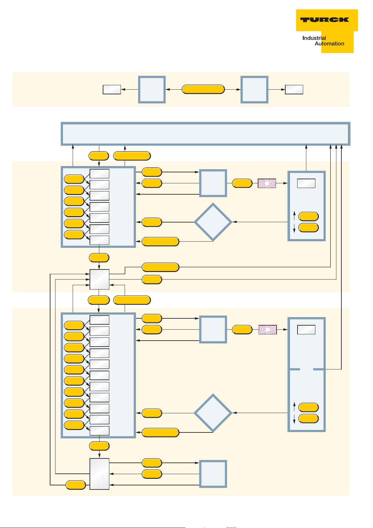
TS…-LUUPN8X-…
TS…-LI2UPN...
Parameter Erläuterung Explanation Explication
Loc sperren inhibit/lock Bloquer
uLoc entsperren enable/unlock Débloquer
Uni Temperatureinheit Temperature unit Unité de température
ou1 Ausgangs- Switching output Fonction de sortie 1
funktion 1 function 1
SP1 Schaltpunkt 1 Switch point 1 Point de commutation 1
SP2 Schaltpunkt 2 Switch point 2 Point de commutation 2
rP1 Rückschaltpunkt 1 Release position 1 Point de déclenchement 1
rP2 Rückschaltpunkt 2 Release position 2 Point de déclenchement 2
ASP Startpunkt analog Analogue starting Point de début
point analogique
AEP Endpunkt analog Analogue Point de fi n
end point analogique
EF zusätzliche Extended Fonctions
Funktionen functions supplémentaires
Hi Maximalwert- Max-value Mémoire valeur
Speicher memory maximale
Lo Minimalwert- Min-value Mémoire valeur
Speicher memory minimale
CoF Offset Justage Offset correction Offset justage
dS1 Verzögerung SP1 Switch point delay SP1 Temporisation SP1
dS2 Verzögerung SP2 Switch point delay SP2 Temporisation SP2
dr1 Verzögerung rP1 Release point delay rP1 Temporisation rP1
dr2 Verzögerung rP2 Release point delay rP2 Temporisation rP2
Fou1 Verhalten Ausg. 1 Performance of out- Comportement sortie 1
bei Fühlerdefekt put 1 with probe fault en cas de défaut de sonde
Fou2 Verhalten Ausg. 2 Performance of out- Comportement sortie 2
bei Fühlerdefekt put 2 with probe fault en cas de défaut de sonde
P-n Verhalten Schalt- Performance Comportement
ausgang switching output sortie de commutation
diS Display- Display update Actualisation affi cheur
Aktualisierung
rES zurück in den Reset to default Remise à l’état par
Auslieferzustand settings défault
SoF Software-Version Software version Version logiciel
20 /0208 Hans Turck GmbH & Co.KG • D–45466 Mülheim an der Ruhr
•
www.turck.com
Page 65

0208 Hans Turck GmbH & Co.KG • D–45466 Mülheim an der Ruhr
•
www.turck.com
Page 66

erase
value
(HI and LO)
or
change
value
extended
functions
Uni
ou1
SP1
rP1
SP2
15 s
yes
no
change
value
> 5 s
EF
show
value
store
value
?
standard
functions
SOF
15 s
show
value
15 s
15 s
15 s
15 s
Mode
Mode
Mode
Mode
Mode
Mode
Enter
Mode + Set
Mode
Mode
Set
Set
Mode
Set
15 s
yes
no
> 5 s
show
value
store
value
?
Enter
Mode + Set
Mode
Set
Set
Mode
Set
Mode
Mode
Mode
Mode
Mode
Mode
Mode
Mode
Mode
Mode
Mode
Set
no flashing:flashing
no flashing:flashing
run-mode
ou2
rP2
HI
LO
COF
dr1
dS1
Fou1
Fou2
diS
P-n
15 s
ASP
AEP
dS2
dr2
Fou2
Fou1
rES P-n
diS
rES
*
*
*
*
*
*
*
*
*
Mode + SetMode
Mode + SetSet
Mode
* only with version LI2UPN8X
* only with version LI2UPN8X
lock
push-
buttons
10 s
unlock
push-
buttons
10 s
LocuLoc
Mode + Set
lock-function
Mode
TS…-…-LI2UPN8X-…
TS…-…-LUUPN8X-…
Hans Turck GmbH & Co.KG • D–45466 Mülheim an der Ruhr
•
www.turck.com 0208
Page 67

0208 Hans Turck GmbH & Co.KG • D–45466 Mülheim an der Ruhr
•
www.turck.com
Page 68

www.turck.com
*D101601ßß0208*
Hans Turck GmbH & Co.KG • D–45466 Mülheim an der Ruhr
Hans Turck GmbH & Co. KG
45472 Mülheim an der Ruhr,
Germany
Witzlebenstraße 7
Tel. +49 (0) 208 4952-0
Fax +49 (0) 208 4952-264
E-Mail more@turck.com
Internet www.turck.com
•
www.turck.com 0208
D101601 0208
 Loading...