

turck TN915-Q120L130-H1147, TN920-Q120L130-H1147, TN921-Q120L130-H1147, TN865-Q175L200-H1147, TN902-Q175L200-H1147 Operating Instructions Manual
...Page 1

Your Global Automation Partner
Operating Instructions
TN…-Q…L…-H1147
UHF Read/Write Heads
Page 2

2
Hans Turck GmbH & Co. KG | T +49 208 4952-0 | F +49 208 4952-264 | more@turck.com | www.turck.com
Contents
Page 3

3
V01.00 | 2018/06
1 About These Instructions 5
1.1 Target groups 5
1.2 Explanation of symbols 5
1.3 Other documents 5
1.4 Naming convention 6
1.5 Feedback about these instructions 6
2 Notes on the Product 7
2.1 Product identication 7
2.2 Scope of delivery 7
2.3 Legal requirements 8
2.4 Manufacturer and service 8
3 For Your Safety 9
3.1 Intended use 9
3.2 Obvious misuse 9
3.3 General safety notes 10
4 Product Description 11
4.1 Device overview 11
4.1.1 Indication elements 11
4.2 Properties and features 11
4.3 Operating principle 12
4.4 Functions and operating modes 12
4.4.1 Operating frequency 13
4.4.2 Combination of UHF read/write heads and tags 13
4.5 Technical accessories 14
5 Mounting 15
5.1 Screw fastening on a mounting plate 16
5.2 Mounting with an application-specic adapter 17
5.3 Mast/tube mounting 18
5.4 Mounting with the RH-Q240L280/Q280L640 arm bracket 19
6 Connection 20
6.1 Wiring diagrams 20
7 Commissioning 21
8 Operation 21
8.1 LEDs 21
9 Setting and Parameterization 22
9.1 Connecting read/write heads with the PC 22
9.1.1 Connecting the read/write heads with a PC via the RFID interface 22
9.1.2 Connecting read/write heads with a PC via the interface converter 23
9.1.3 Creating a project in PACTware 24
9.2 Testing the read/write heads 27
9.2.1 Starting the RFID test 27
Contents
Page 4

4
Hans Turck GmbH & Co. KG | T +49 208 4952-0 | F +49 208 4952-264 | more@turck.com | www.turck.com
9.2.2 Start window – Overview 28
9.2.3 “RFID Test” – Main menu 29
9.2.4 “RFID Test” – “Basic Test” window 30
9.2.5 “RFID Test” – “Tag Actions” window 31
9.2.6 “RFID Test” – “Logger” window 34
9.2.7 “HF diagnosis” window 35
9.3 Setting read/write heads parameters via the DTM 36
9.3.1 Starting the extended read/write head parameter setting 36
9.3.2 Main menu – Overview 37
9.3.3 Choosing the access level 38
9.3.4 “Basic setup” 39
9.3.5 “Antenna” 39
9.3.6 “Communication” 39
9.3.7 “EPC Class1 Gen2” 39
9.3.8 “Error Handling” – Selectable parameters 39
9.3.9 “Event Handling” – Selectable parameters 39
9.3.10 “Post Read Filter” – Selectable parameters 39
9.3.11 “Signaling” – Selectable parameters 39
9.4 Device information via the DTM 40
10 Troubleshooting 42
11 Maintenance 42
12 Repair 42
12.1 Returning devices 42
13 Disposal 42
14 Technical Data 43
14.1 Technical data – TN865… 43
14.2 Technical data – TN902… 44
14.3 Technical data – TN840/920… 45
14.4 Technical data – TN917… 46
14.5 Technical data – TN866… 47
14.6 Technical data – TN902/915… 48
14.7 Technical data – TN920… 49
14.8 Technical data – TN921… 50
15 Appendix: Conformity Declarations and Approvals 51
15.1 EU conformity declaration 51
15.2 FCC/IC Digital Device Limitations – TN902-Q120L130-H1147 51
15.3 FCC/IC Digital Device Limitations – TN902-Q175L200-H1147 52
Page 5
5
V01.00 | 2018/06
1 About These Instructions
This manual describes the setup, the functions and use of the product and helps you to operate
the product for its intended use. Read the instructions carefully prior to using the product. This
will prevent the risk of personal injury and damage to property. Keep these instructions safe
during the service life of the product. If the product is passed on, pass on these instructions as
well.
1.1 Target groups
These instructions are written for suitably qualified and trained personnel and must be read by
anyone entrusted with the mounting, commissioning, operation, maintenance, disassembly or
disposal of the device.
1.2 Explanation of symbols
The following symbols are used in these instructions:
DANGER
DANGER indicates an immediate hazardous situation, which, if not avoided, will result
in death or serious injury.
WARNING
WARNING indicates a possible hazardous situation with the risk of death or serious
injury if it is not prevented.
NOTICE
NOTICE indicates a situation that may cause possible damage to property if it is not
prevented.
NOTE
NOTE indicates tips, recommendations and important information. The notes contain
information, particular operating steps that facilitate work and possibly help to avoid
additional work resulting from incorrect procedures.
MANDATORY ACTION
This symbol denotes actions that the user must carry out.
RESULT OF ACTION
This symbol denotes the relevant results of actions and procedures.
1.3 Other documents
Besides this document the following material can be found on the Internet at www.turck.com:
■
Data sheet
■
Quick start guide
■
RFID engineering manual
■
Startup manuals
Page 6

6
Hans Turck GmbH & Co. KG | T +49 208 4952-0 | F +49 208 4952-264 | more@turck.com | www.turck.com
About These Instructions
1.4 Naming convention
Common synonyms for “tags” are “data carriers”, “transponders” and “mobile data memory”.
Read/write heads are also called “transceivers” or “readers”.
1.5 Feedback about these instructions
We make every effort to ensure that these instructions are as informative and as clear as possible. If you have any suggestions for improving the design or if some information is missing in
the document, please send your suggestions to techdoc@turck.com.
Page 7

7
V01.00 | 2018/06
2 Notes on the Product
2.1 Product identication
These instructions apply to the following UHF read/write heads:
Type code Operating frequency Region
TN865-Q120L130-H1147 865…868 MHz Europe
TN902-Q120L130-H1147 902…928 MHz North America (USA,
Canada, Mexico)
TN840/920-Q120L130- H1147 920.5…924.5MHz China
TN917-Q120L130-H1147 917…920.8 MHz Korea
TN866-Q120L130-H1147 866…868 MHz Russia
TN902/915-Q120L130-H1147 915…928MHz Brazil
TN920-Q120L130-H1147 920…926 MHz Australia, New Zealand
TN921-Q120L130-H1147 920…925 MHz Singapore
TN865-Q175L200-H1147 865…868 MHz Europe
TN902-Q175L200-H1147 902…928 MHz North America (USA,
Canada, Mexico)
TN840/920-Q175L200- H1147 920.5…924.5MHz China
TN917-Q175L200-H1147 917…920.8 MHz Korea
TN866-Q175L200-H1147 866…868 MHz Russia
TN902/915-Q175L200-H1147 915…928MHz Brazil
TN920-Q175L200-H1147 920…926 MHz Australia, New Zealand
TN921-Q175L200-H1147 920…925 MHz Singapore
2.2 Scope of delivery
The following are included in the scope of delivery:
■
Read/write head
■
Quick start guide
■
Mounting aid incl. fixing clamp and 2 M6 ×8 screws
■
Grounding set
■
4 screw covers
■
Turck RFID-DVD
■
1 screw cap M12
Page 8

8
Hans Turck GmbH & Co. KG | T +49 208 4952-0 | F +49 208 4952-264 | more@turck.com | www.turck.com
Notes on the Product
2.3 Legal requirements
The devices comply with the following regulations:
Device Region of use Regulations
TN865-Q…L…-H1147 e.g. Europe – 2014/30/EU (electromagnetic compatibility)
– 2014/35/EU (low voltage)
– 2014/53/EC (RED Directive)
– 2011/65/EU (RoHS)
TN902-Q…L…-H1147 USA FCC Rules Part 15
Canada Industry Canada RSS-210
Mexico IFETEL, Dictamen (electrical safety)
TN840/920-Q120L130- H1147 China SRRC
TN917-Q120L130-H1147 Korea KCC
TN866-Q120L130-H1147 Russia Import license for wireless devices
TN902/915-Q120L130-H1147 Brazil ANATEL
TN920-Q120L130-H1147 Australia ACMA
New Zealand RSM
TN921-Q…L…-H1147 Singapore IDMA
NOTE
Additional certification may be required, depending on the region of use. Tests for
other national approvals can be carried out and implemented if necessary.
2.4 Manufacturer and service
Turck supports you in your projects – from the initial analysis right through to the commissioning of your application. The Turck product database offers you several software tools for programming, configuring or commissioning, as well as data sheets and CAD files in many export
formats. You can access the Product Database directly via the following address:
www.turck.de/products
For further inquiries in Germany contact the Sales and Service Team on:
Sales: +49 208 4952-380
Technical: +49 208 4952-390
For overseas inquiries contact your national Turck representative.
Hans Turck GmbH & Co. KG
Witzlebenstraße 7
45472 Mülheim an der Ruhr
Germany
Page 9

9
V01.00 | 2018/06
3 For Your Safety
The product is designed according to state of the art technology. Residual hazards, however,
still exist. Observe the following warnings and safety regulations in order to prevent danger to
persons and property. Turck accepts no liability for damage caused by failure to observe these
warnings and safety instructions.
3.1 Intended use
The devices are designed only for use in industrial areas.
The BL ident® read/write heads are used for contactless data exchange with the BL ident® tags
in the BL ident® UHF RFID system. The following table shows the operating frequency of the
devices.
Type code Operating frequency
TN865-… 865…868 MHz
TN902-… 902…928 MHz
TN840/920-… 840.5…844.5MHz and 920.5…924.5MHz
TN917-… 917…920.8 MHz
TN866-… 866…868 MHz
TN902/915-… 902…907.5MHz and 915…928MHz
These devices may only be started up under the following conditions:
■
The particular frequency range is permissible for the use of UHF-RFID.
■
The operating frequency range of the devices is compliant with the permissible UHF RFID
range of the region.
■
A valid certification and/or approval is available for the region of use.
The device must only be used as described in these instructions. Any other use is not in accordance with the intended use. Turck accepts no liability for any resulting damage.
3.2 Obvious misuse
■
The devices are not suitable for the protection of persons or property and must not be used
in safety-related applications.
■
The devices must not be used under water.
Page 10

10
Hans Turck GmbH & Co. KG | T +49 208 4952-0 | F +49 208 4952-264 | more@turck.com | www.turck.com
For Your Safety
3.3 General safety notes
■
The device must only be fitted, installed, set, operated and maintained by trained and qualified personnel.
■
The devices only meet the EMC requirements for industrial areas and are not suitable for use
in residential areas.
■
Only use the devices in compliance with the applicable national and international regulations, standards and laws.
■
Any extended stay within the area of radiation of the UHF read/write heads may be harmful
to health. Observe minimum distances from the actively radiating surface of the UHF read/
write head:
Region max. permissible total radiant
output power
Safety distance
Europe, Russia, China 2 W ERP (according to ETSI) > 0.24 m
USA, Canada, Brazil, Korea,
Australia, New Zealand
4 W EIRP > 0.30 m
Singapore 0.5 W ERP > 0.24 m
■
The radiation of the UHF read/write heads may have an adverse effect on the operation of
electrically controlled medical equipment. Keep an additional distance from active radiation
sources up to the maximum transmission distance.
Page 11
11
V01.00 | 2018/06
4 Product Description
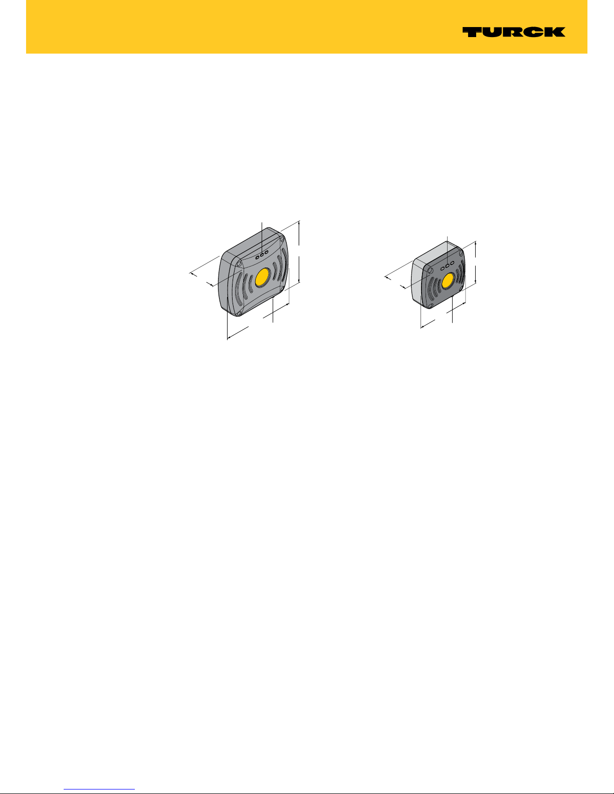
The UHF read/write heads have a rectangular design (120 × 130 mm or 175 × 200 mm). The
devices are rated to degree of protection IP67 and are contained in an aluminum housing with
a plastic front. The power supply to the device and data exchange with the controller are implemented via a BL ident® RFID interface. A 4-pin M12 x 1 connector is provided for connecting to
the RFID interface.
4.1 Device overview
200
175
60
M12
LED
130
120
60
M12
LED
Fig. 1: Dimensions
– TN…-Q175L200-H1147
Fig. 2: Dimensions
– TN…-Q120L130-H1147
4.1.1 Indication elements
Each device is provided with three adjustable LEDs. An audible alarm can also be set using
software tools.
4.2 Properties and features
■
Robust read/write heads in industrial design
■
Writing and reading of passive UHF tags in single and multitag mode
■
Read/write distances up to several meters (depending on ambient conditions, the parameter
setting of the read/write head and the selected tag)
■
Compact design for mounting in restricted spaces
Page 12
12
Hans Turck GmbH & Co. KG | T +49 208 4952-0 | F +49 208 4952-264 | more@turck.com | www.turck.com
Product Description
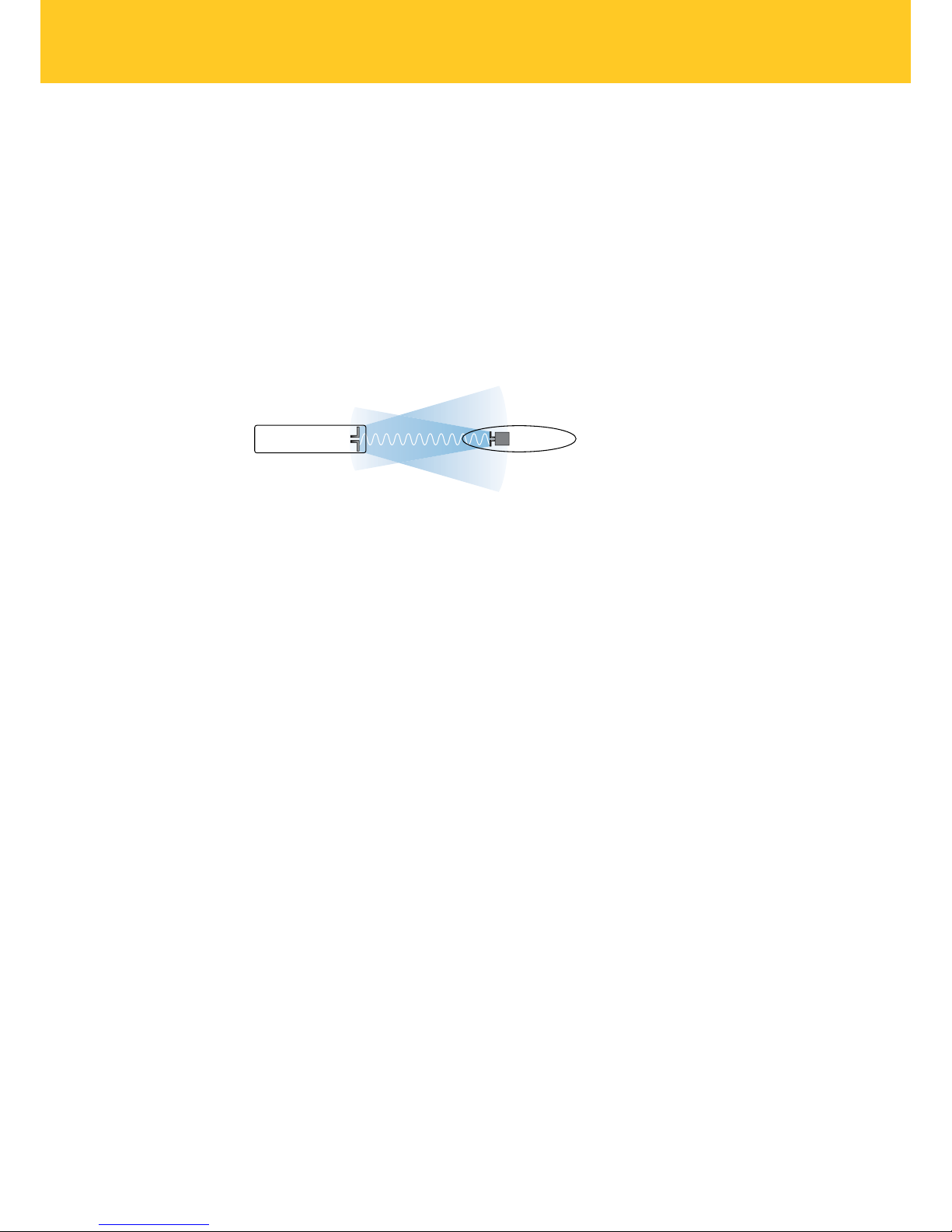
4.3 Operating principle
The read/write heads are used for contactless data exchange with tags. For this the controller
sends commands and data via the interface to the read/write head and receives the corresponding response data from the read/write head. The reading of the IDs of all RFID tags in the
read area or the writing of an RFID tag with a specific production date are examples of typical
commands. To communicate with the tag, the data of the read/write head is coded and transferred via an electromagnetic field, which at the same time supplies the tags with power.
A read/write head contains a transmitter and a receiver, an interface to the interface and a
coupling element (coil and dipole antenna) for communicating with the tag. Electromagnetic
wave propagation is used for the transmission between read/write head and tag on devices for
the UHF range.
Fig. 3: Operating principle of UHF-RFID
The antenna of the read/write head generates electromagnetic waves. This produces a transmission window as a so-called air interface in which the data exchange with the tag takes place.
The size of the transmission window depends on the combination of read/write heads and tags,
as well as on the relevant environmental conditions.
Each read/write head can communicate with a number of tags. This requires the read/write
head and the tag to operate in the same frequency range. Depending on the power and
frequency used, the device ranges vary from a few millimeters up to several meters. The specified maximum read/write distances only represent typical values under laboratory conditions
without allowing for the effect of materials. The achievable distances may vary due to component tolerances, the mounting situation in the application, ambient conditions and the effect of
materials (particularly metal and liquids).
4.4 Functions and operating modes
The devices enable passive UHF tags to be read or written in single and multi-tag operation.
For this the devices form a transmission zone that varies in size and range according to the tags
used and the operating conditions of the application. Refer to the data sheets for the applicable
maximum read/write distances. The devices can be fully tested, configured and parameterized
from a PC using the specified software tools.
IC
Read/write head
Data carrier
UHF: electromagnetic wave
Page 13

13
V01.00 | 2018/06
4.4.1 Operating frequency
The Turck BL ident® UHF system uses nationally specified transmission frequencies for the communication between the tags and read/write heads. These national operating frequencies for
UHF are the frequency ranges that are individually specified by the national regulation bodies.
The operating frequency of the devices in the UHF band is for example 865…868 MHz for Europe and 902…928 MHz for the USA. The BL ident® read/write heads in the UHF band can therefore only be used in the countries they are intended for and must not be put into operation
outside of these regions. As the BL ident® UHF tags are passive, and therefore do not radiate
their own radio waves, these are suitable for use worldwide.
Turck offers different tag variants that are specially designed and optimized for national
frequency bands in order to achieve as large a communication range as possible. Wide-band
multi-range tags for international use are also available as an alternative.
The various Turck read/write heads support the following operating frequencies:
■
865...868 MHz (e.g. for Europe)
■
866…868 MHz (e.g. for Russia)
■
902...928 MHz (e.g. for USA and Canada)
■
920…925 MHz (e.g. for China and Singapore)
■
902...907.5 MHz and 915...928 MHz (e.g. Brazil)
■
917...920.8 MHz (e.g. for Korea)
The relevant national specifications for UHF such as frequency range, output and the status of
any national regulations can be obtained from the Internet at:
http://www.gs1.org/docs/epcglobal/UHF_Regulations.pdf
For more detailed information please contact the regulation authorities of the country where
you wish to use the UHF RFID system.
HF RFID systems can be run parallel to UHF RFID systems in an installation.
4.4.2 Combination of UHF read/write heads and tags
The UHF read/write heads form a transmission zone for which the size depends on the combination of read/write head and tag. The listed maximum read/write distances only represent
typical values under laboratory conditions without the effect of materials.
The achievable distances may be different due to component tolerances, mounting location in
the application, ambient conditions and the effect of materials (particularly metal).
For this reason, the application must be tested in all cases under real conditions (particularly
with read and write operations in motion).
Page 14

14
Hans Turck GmbH & Co. KG | T +49 208 4952-0 | F +49 208 4952-264 | more@turck.com | www.turck.com
Product Description
4.5 Technical accessories
The following accessories are not supplied with the device:
Dimension drawing Type Ident no. Description
RH-Q240L280/Q280L640 7030296 Arm bracket for UHF read/write heads
Page 15
15
V01.00 | 2018/06
5 Mounting
The devices can be mounted in any position.
Mount the device with the appropriate fixing accessories.
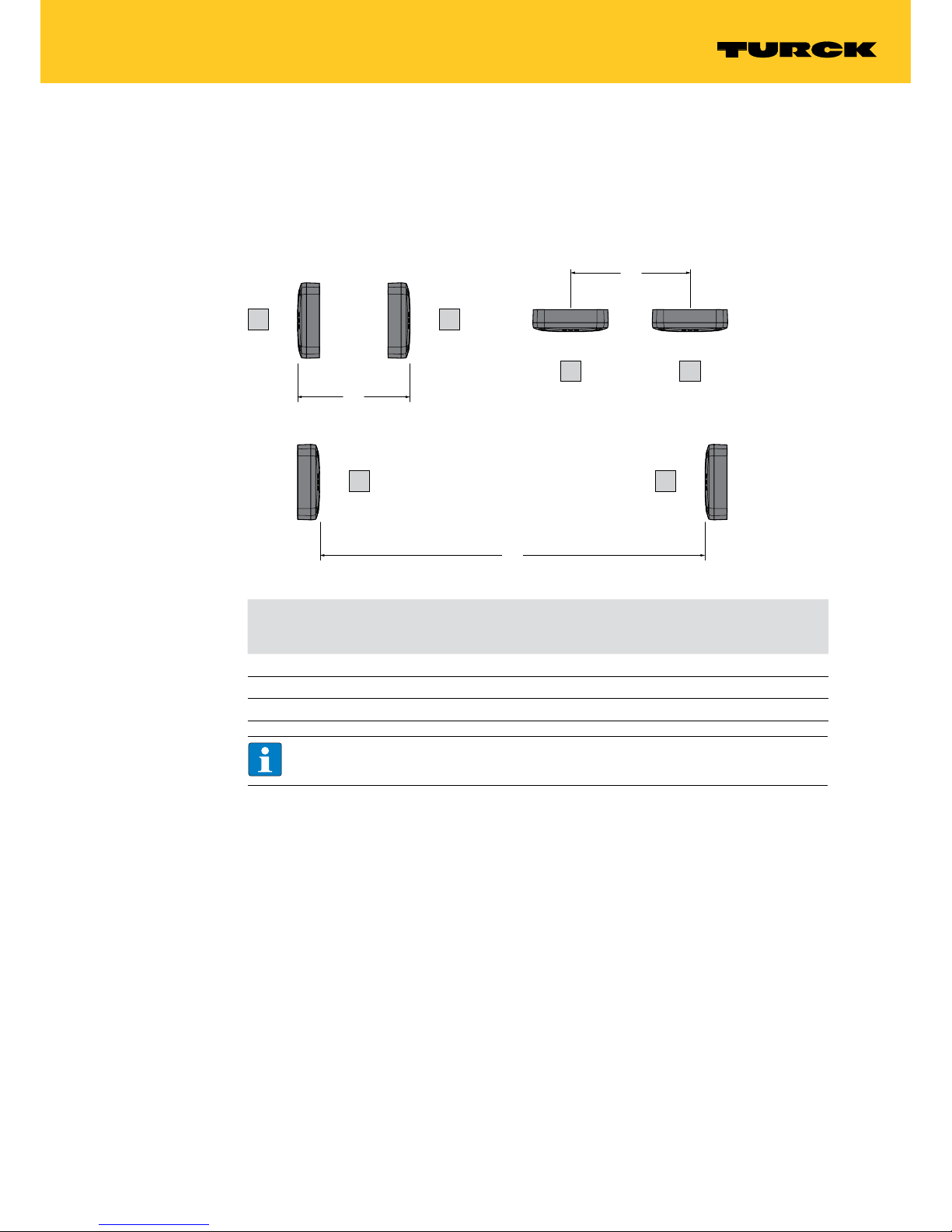
The minimum distance between two read/write heads using the same frequency depends on
the maximum radiant power and the alignment of the antenna.
Fig. 4: Antenna alignment
Antenna alignment Minimum distance D for TN…-
-Q175L200-H1147 with ERP = 1 W
Minimum distance D for TN…-
-Q120L130-H1147 with ERP = 0.5
W
Back to back 0.5m 0.25m
Side by side 1m 0.5m
Front to front 2.5m 1.25m
NOTE
The stated values do not take into account the effect of the tags.
Tag Tag
TagTag
Tag Ta g
D
D
D
Page 16
16
Hans Turck GmbH & Co. KG | T +49 208 4952-0 | F +49 208 4952-264 | more@turck.com | www.turck.com
Mounting
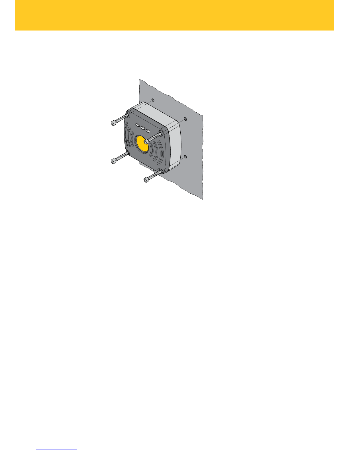
5.1 Screw fastening on a mounting plate
Fasten the device with four M5 × 35 cylinder screws on a pre-drilled mounting plate.
Fig. 5: Screwing the read/write head onto the mounting plate
Page 17

17
V01.00 | 2018/06
5.2 Mounting with an application-specic adapter
Make the adapter according to the following dimension drawings.
Fig. 6: Dimension drawing for TN…-Q120…
Fig. 7: Dimension drawing for TN…-Q175…
Fit the device at the intended mounting location
60
24
M6 x 8 (2x)
19.5
59
A
A
A - A
M5 x 35 (4x)
27
130
22
100
120
100
24
60
175
150
44
200
59
A - A
M5 x 35 (4x)
M6 x 10 (2x)
150
27
AA
Page 18

18
Hans Turck GmbH & Co. KG | T +49 208 4952-0 | F +49 208 4952-264 | more@turck.com | www.turck.com
Mounting
5.3 Mast/tube mounting
Fit the device with the intended mounting aid as shown in the following figure.
M6 x 8
Fig. 8: Mast/tube mounting
Page 19

19
V01.00 | 2018/06
5.4 Mounting with the RH-Q240L280/Q280L640 arm bracket
The RH-Q240L280/Q280L640 arm bracket (Ident no. 7030296) is not supplied with the device
and must be ordered separately.
Fasten the device with two M6 × 12 screws through the fixing holes of the read/write head
and arm bracket.
Fig. 9: Mounting read/write heads with an arm bracket
M6 x 12
Page 20

20
Hans Turck GmbH & Co. KG | T +49 208 4952-0 | F +49 208 4952-264 | more@turck.com | www.turck.com
Connection
6 Connection
DANGER
Effect on electrically controlled medical devices such as pacemakers
Danger to life due to malfunction or failure of medical equipment
Determine and ensure the recommended distances between medical equipment
and radiation sources.
Connect the power supply via the M12 plug connector to the interface as shown in wiring
diagrams below.
6.1 Wiring diagrams
Pin layout Wiring diagram
Fig. 10: Connection cables …/S2500
Pin layout Wiring diagram
Fig. 11: Connection cables …/S2501
Pin layout Wiring diagram
1 BN
3 BU
4 WH
2 BK
+
–
Data
Data
Fig. 12: Connection cables …/S2503
Page 21

21
V01.00 | 2018/06
7 Commissioning
The device is operational automatically once the cables are connected and the power supply is
switched on.
The planning and preparation of an RFID system require different measures, depending on the
application. Further information on this is provided in the RFID engineering manual.
8 Operation
8.1 LEDs
The devices are provided with three LEDs for displaying the status of the device. The indication
functions can be adjusted for the specific application via the DTM. The LEDs are factory set with
the following indication functions after a voltage reset:
LED Color State Meaning
1 (operating state) Green Off No operating voltage present
Lit Operating voltage connected
Off 0.2 s Tag detected
2 (state of the wireless field) Yellow Off Wireless field deactivated
Lit Wireless field activated
3 (errors) Red Off No internal error
Lit Internal error detected
Page 22

22
Hans Turck GmbH & Co. KG | T +49 208 4952-0 | F +49 208 4952-264 | more@turck.com | www.turck.com
Setting and Parameterization
9 Setting and Parameterization
The read/write heads can be assigned additional parameters via the DTM in the PACTware™ 5.0
FDT frame application. FDT and DTM can be downloaded free of charge from www.turck.com.
9.1 Connecting read/write heads with the PC
In order to carry out extended parameter setting with the DTM, the read/write head must be
connected with a PC. The read/write heads can be connected with a PC via a TBEN-RFID interface (e.g. TBEN-S2-2RFID-4DXP) or via the STW-RS485-USB interface converter.
9.1.1 Connecting the read/write heads with a PC via the RFID interface
Connect the read/write head to the RFID interface converter using an appropriate connection
cable (e.g. RK4.5T-2RS45/S2500).
Connect the RFID interface via a suitable Ethernet cable to the PC.
Connect the RFID interface to a power supply.
Fig. 13: Connecting the read/write head with a PC via the TBEN-S2-2RFID-4DXP
UHF RFID read/write head
e.g. TNxxx-Q175L200-H1147
RFID interface
TBEN-S2-2RFID-4DXP
RFID cable
e.g. RK4.5T-…-RS4.5T/S2500
Ethernet cable
e.g. RSSD-RJ45…
PC / Notebook
with Ethernet interface
Page 23

23
V01.00 | 2018/06
9.1.2 Connecting read/write heads with a PC via the interface converter
The following accessories are required to connect read/write heads to a PC:
■
STW-RS485-USB interface converter (Ident no. 7030354)
■
STW-RS485-USB-PS power supply unit (Ident no. 7030355),
Accessories are not supplied with the device and must be ordered separately.
Connect the read/write head to the interface converter using a suitable connection cable (e.g.
RK4.5T-2/S2500) according to the following color coding:
STW-RS485-USB Connectors …/S2500 Male connector …/
S2501
Male connector …/
S2503
VCC Brown (BN) Brown (BN) Red (RD)
GND Blue (BU) Blue (BU) Black (BK)
RS485-A White (WH) Black (BK) White (WH)
RS485-B Black (BK) White (WH) Blue (BU)
Connect a USB cable to the interface converter (USB1.1 type B).
Connect the open end of the USB cable to a free USB port on the PC (USB1.1 type A).
Set the switches on the side of the interface converter for the termination to “ON”.
Connect the interface converter via the STW power supply unit to a power supply.
Fig. 14: Connecting the read/write head via the interface converter with a PC
UHF RFID read/write head
e.g. TNxxx-Q175L200-H1147
Interface converter
STW-RS485-USB
Power supply
STW-RS485-USB-PS
RFID cable
e.g. RK4.5T/S2500
PC / Notebook
with USB-interface
Page 24

24
Hans Turck GmbH & Co. KG | T +49 208 4952-0 | F +49 208 4952-264 | more@turck.com | www.turck.com
Setting and Parameterization
9.1.3 Creating a project in PACTware
Launch PACTware™.
Right-click Host PC in the project tree.
Click “Add device”.
Fig. 15: Adding a device in PACTware™
NOTE
The example shows the connection via an interface converter. When using a TBENRFID interface, choose the “BL Service Ethernet” option.
Example: Select “RS485 RFID” to connect the read/write head to the PC via the RS485
interface.
Fig. 16: Example: Selecting “RS485 RFID”
Page 25

25
V01.00 | 2018/06
Double-click “RS485 RFID” in the project tree.
Select the COM port. The COM port to which the device is connected is shown in the device
manager in the control panel of the PC (COM & LPT).
Set the baud rate.
Fig. 17: Setting up the RS485 interface
Confirm the changes by clicking “Accept”.
Right-click “RS485 RFID” in the project tree.
Click “Add device”.
Fig. 18: Adding the device to the RS485 interface
Page 26

26
Hans Turck GmbH & Co. KG | T +49 208 4952-0 | F +49 208 4952-264 | more@turck.com | www.turck.com
Setting and Parameterization
Select the connected device (example: TN865-Q175L200-H1147).
Confirm the selection with OK or double-click the device.
Fig. 19: Select the connected device (example: TN865-Q175L200-H1147)
Right-click the device in the project tree.
Establish a connection.
Fig. 20: Establishing a connection
The “RFID Test” and "Parameterization” functions can be started from the project tree at “Ad-
ditional functions”.
Page 27

27
V01.00 | 2018/06
9.2 Testing the read/write heads
The following functions can be executed via the RFID Test in the DTM:
■
Displaying read data
■
Displaying the protocol of the communication between host or PC and read/write head
■
Logging of the interface communication between host or PC and read/write head
■
Sending of user-specific deBus commands
■
Writing of tags with a user-defined number
■
Sending tag-specific commands
Requirements for the RFID test:
■
PACTware™ must be installed.
■
The DTM for UHF read/write heads must be installed.
■
The connection between the read/write head and the PC must be established.
■
A project must have been created in PACTwareTM.
9.2.1 Starting the RFID test
Right-click the device in the project tree.
In the context menu choose “Additional functions” “RFID Test”.
Fig. 21: Starting the RFID test
Page 28

28
Hans Turck GmbH & Co. KG | T +49 208 4952-0 | F +49 208 4952-264 | more@turck.com | www.turck.com
Setting and Parameterization
9.2.2 Start window – Overview
The “RFID Test” window consists of the following elements:
■
Main menu
■
Basic test
■
Tag actions
■
Logger
Fig. 22: “RFID Test” – Start window
Page 29

29
V01.00 | 2018/06
9.2.3 “RFID Test” – Main menu
Fig. 23: “RFID Test” – Main menu
The main menu provides the following functions:
Icon Function Description
Start trigger/ON Starts the trigger for command execution
Stop trigger/OFF Closes the trigger for command execution
Switch on antenna Switches on the read/write head antenna
Switch off antenna Switches off the read/write head antenna. Trigger commands are
ignored.
Configure message content Displays the content to be transferred with a read operation. The
following can be selected:
– Phase
– RSSI
– Socket
– Time
Switch mode (report/polling) Switches between Report mode (automatic read/write) and polling
mode (read/write started through an explicit polling command)
Read read/write head Calls the following information from the read/write head and pro-
vides the information in the “Logger” window:
– Read/write head status
Read read/write head version Calls the following information from the read/write head and pro-
vides the information in the “Logger” window:
– Hardware revision
– Firmware status
– Serial number
Reset read/write head Offers three ways of resetting the read/write head:
– Voltage reset
– Factory reset: Reset to factory settings
– Reset read/write head status
When reset to factory settings, any modified baud rate or RS485
address is not changed because the read/write head could not
otherwise be addressed any longer.
HF diagnosis Opens the window to the HF diagnostics
Page 30

30
Hans Turck GmbH & Co. KG | T +49 208 4952-0 | F +49 208 4952-264 | more@turck.com | www.turck.com
Setting and Parameterization
9.2.4 “RFID Test” – “Basic Test” window
Fig. 24: “RFID Test” – “Basic Test” window
The following functions are available in the “Basic test” window.
Icon Function Description
Polling Shows the first tag in the polling memory of the device in the tag
list. The function is only available in polling mode.
Poll all Shows all tags in the polling memory of the device in the tag list.
The function is only available in polling mode.
Delete polled tags of the read/write head Clears the polling memory of the read/write head
CSV export of the current data Saves the tag list in CSV format
Delete tag list Deletes the list of displayed tags
The queried data is displayed in the tag list. The content of the message can be set via the “Configure message content” function.
Page 31

31
V01.00 | 2018/06
9.2.5 “RFID Test” – “Tag Actions” window
The functions in the “Tag actions” window are available if a tag is marked in the tag list of the
“Basic Test” window.
Fig. 25: “RFID Test” – “Tag Actions” window
The following functions are available in the “Tag actions” window:
Icon Function Description
Read tag Starts the read operation
The chip type is automatically displayed. One word is always read
with the first read operation. The following parameters can be set
for other read operations:
– Memory bank (TID, EPC/UID, PC, access password or kill
password)
– Start word
– Number of words
The read data is displayed in the “Data” area.
Write tag Starts the write operation
The chip type is automatically displayed. The following parameters
can be set for the write operations:
– Memory bank (TID, EPC/UID, PC, access password or kill
password)
– Start word
– Number of words
Data to be written is displayed in the “Data” area.
Switch access password on/off Switches the password for write or read access on or off.
Page 32

32
Hans Turck GmbH & Co. KG | T +49 208 4952-0 | F +49 208 4952-264 | more@turck.com | www.turck.com
Setting and Parameterization
Example: Execute tag actions
Position tag in detection range of the read/write head.
Activate the trigger for the read/write head in the main menu.
Fig. 26: Main menu – Activating trigger
“Basic Test” window: Execute polling command in order to display tag in the tag list.
“Basic Test” window: Select tag from the tag list.
Fig. 27: Select the tag
Page 33

33
V01.00 | 2018/06
“Tag actions” window: Enter required values and confirm entry with ENTER.
Fig. 28: Entering the data
Execute the required function by clicking the appropriate button (here: “Read”).
Fig. 29: Execute tag action (example: “Read”)
Page 34

34
Hans Turck GmbH & Co. KG | T +49 208 4952-0 | F +49 208 4952-264 | more@turck.com | www.turck.com
Setting and Parameterization
Successful access is displayed via the status message at the bottom of the window.
Fig. 30: Example: Successful read operation
9.2.6 “RFID Test” – “Logger” window
The “Logger” window displays read/write information and error messages.
The list can be cleared via the “Delete” button.
Fig. 31: Messages in the “Logger” window
Page 35

35
V01.00 | 2018/06
9.2.7 “HF diagnosis” window
The current power level of the read/write head is displayed for each channel in the “HF diagnosis” window.
Fig. 32: “HF diagnosis” window
The following functions can be executed in the “HF diagnosis” window:
Icon Function Description
Start/stop HF diagnostic Starts or closes the HF diagnostics
Delete values Deletes the displayed values
Page 36

36
Hans Turck GmbH & Co. KG | T +49 208 4952-0 | F +49 208 4952-264 | more@turck.com | www.turck.com
Setting and Parameterization
9.3 Setting read/write heads parameters via the DTM
The functions of the read/write heads can be assigned additional parameters via the parameterization function of the DTM.
NOTE
The parameterization function is only available in English. All parameters are written in
the DTM.
The individual read/write heads are available in different variants. When a connection is made
to a connected read/write head, the DTM automatically detects the relevant device and deactivates menu items that are not supported. The connection cannot be established if a different
variant than set in the project tree is connected.
Requirements for extended parameter setting
■
PACTware™ must be installed.
■
The DTM for UHF read/write heads must be installed.
■
The connection between the read/write head and the PC must be established.
■
A project must have been created in PACTwareTM.
9.3.1 Starting the extended read/write head parameter setting
Right-click the device in the project tree.
Choose “Parameter” “Parameterization” or “Online parameterization” in the context menu.
Fig. 33: Example: Starting online parameter setting via the context menu
Page 37

37
V01.00 | 2018/06
9.3.2 Main menu – Overview
Fig. 34: Parameterization – Main menu
The main menu provides the following functions:
Icon Function Description
Help on the DTM Starts the DTM help
Help on the device Opens the data sheet of the connected read/write head
Activating/deactivating Expert mode Opens the drop-down menu to select the access level. The follow-
ing access levels are available:
– Basic (default setting)
– Advanced
– Administrator
Channel-wise display Toggles the view between standard display and channel-wise
display
Load parameters from the database Loads previously stored parameters from the database (e.g. an
existing project)
Transfers parameters to the database Transfers the current read/write head parameters to the database
of the project
Read parameters from the device Calls up the parameters saved on the connected read/write head
Transfer parameters to the device Transfers the parameter set in the DTM to the device
Compare values with database Compares the values displayed in the DTM with the values saved in
the database
CSV export Exports the current values from the DTM to a CSV file
Page 38

38
Hans Turck GmbH & Co. KG | T +49 208 4952-0 | F +49 208 4952-264 | more@turck.com | www.turck.com
Setting and Parameterization
The following setup windows can be opened in tabs via the main menu:
■
Basic setup
■
Antenna
■
Communication
■
EPC Class1 Gen2
■
Error handling
■
Event handling
■
Post read filter
■
Signaling
9.3.3 Choosing the access level
Three access levels are available for setting the device parameters. Different parameters can be
set depending on the access level.
NOTE
Modifications made in the “Administrator” access level can result in serious changes in
operation. The “Administrator” access level is therefore only available for Turck service
technicians. All relevant settings for the successful parameter setting of an application
are available in the “Advanced” access level.
Access level Description Initial password
Basic Basis access for initial configuration and
commissioning
Not required
Advanced Extended access, e.g. for applications Not required
Administrator Administrator access for critical security or wire-
less settings
Required
The current access level is displayed in the top right screen area of the DTM.
Fig. 35: Display of the access level
Page 39

39
V01.00 | 2018/06
9.3.4 “Basic setup”
The “Basic Setup” tab is used to set the basic parameters for the read/write heads. All parameters and the settable values are written in the DTM.
9.3.5 “Antenna”
The “Antenna” tab is used to set the antenna parameters for the read/write heads. All param-
eters and the settable values are written in the DTM.
9.3.6 “Communication”
The “Communication” tab is used to set the parameters for the configuration of the deBus messages. All parameters and the settable values are written in the DTM.
9.3.7 “EPC Class1 Gen2”
The “EPC Class1 Gen2” tab is used to set the EPC Class1 Gen2 parameters for the air interface.
The parameters set are used if the read/write head performs an Inventory command. All parameters and the settable values are written in the DTM.
9.3.8 “Error Handling” – Selectable parameters
The behavior of the read/write head in response to different events (e.g. LED behavior) can be
set in the “Error Handling” tab. All parameters and the settable values are written in the DTM.
9.3.9 “Event Handling” – Selectable parameters
The behavior of the read/write head in response to errors (e.g. LED behavior) can be set in the
“Event Handling” tab. All parameters and the settable values are written in the DTM.
9.3.10 “Post Read Filter” – Selectable parameters
The parameters for filtering event messages can be set in the “Post Read Filter” tab.
The set filters do not reduce the data traffic on the air interface and are not suitable for multitag
applications with many tags or high passing speeds. All parameters and the settable values are
written in the DTM.
9.3.11 “Signaling” – Selectable parameters
The “Signaling” tab enables the default settings for the LEDs to be edited. All parameters and
the settable values are written in the DTM.
Page 40

40
Hans Turck GmbH & Co. KG | T +49 208 4952-0 | F +49 208 4952-264 | more@turck.com | www.turck.com
Setting and Parameterization
9.4 Device information via the DTM
The DTM provides access to hardware and software information as well as regulations on the
connected device.
Right-click the device in the project tree.
Choose “Additional functions” Select “Identify”.
Fig. 36: Calling up “Identify”
Page 41

41
V01.00 | 2018/06
The DTM shows the available information on the device according to the selected access
level.
Fig. 37: Example: Device information for TN865-Q175L200-H1147 in the “Advanced” access
level
Page 42

42
Hans Turck GmbH & Co. KG | T +49 208 4952-0 | F +49 208 4952-264 | more@turck.com | www.turck.com
Troubleshooting
10 Troubleshooting
If the device does not function as expected, first check whether ambient interference is present.
If there is no ambient interference present, check the connections of the device for faults.
If there are no faults, there is a device malfunction. In this case, decommission the device and
replace it with a new device of the same type.
11 Maintenance
Ensure regularly that the plug connections and cables are in good condition.
The devices are maintenance-free, clean dry if required.
12 Repair
The device must not be repaired by the user. The device must be decommissioned if it is faulty.
Observe our return acceptance conditions when returning the device to Turck.
12.1 Returning devices
If a device has to be returned, bear in mind that only devices with a decontamination declaration will be accepted. This is available at
https://www.turck.de/en/retoure-service-6079.php
and must be completely filled in, and affixed securely and weather-proof to the outside of the
packaging.
13 Disposal
The devices must be disposed of correctly and must not be included in normal household
garbage.
Page 43

43
V01.00 | 2018/06
14 Technical Data
14.1 Technical data – TN865…
Technical data TN865-Q120… TN865-Q175…
Mounting condition Non-flush Non-flush
Ambient temperature -25…+50 °C -25…+50 °C
Operating voltage 12…24 VDC 12…24 VDC
Data transmission Electromagnetic AC field Electromagnetic AC field
Operating frequency 865…868 MHz 865…868 MHz
Wireless communication and
protocol standards
ISO 18000-6C
EN 302208
EPCglobal Gen 2
ISO 18000-6C
EN 302208
EPCglobal Gen 2
Channel distance 200/600 kHz 200/600 kHz
Output power 0.5 W (ERP), adjustable 1 W (ERP), adjustable
Antenna polarization Clockwise Clockwise
Antenna half power beam width 110° 90°
Read/write distance max. 1500 mm 4000 mm
Output function 4-wire, read/write 4-wire, read/write
Design Rectangular Rectangular
Dimensions 130 × 120 × 60 mm 200 × 175 × 60 mm
Housing material Aluminum, AL, silver Aluminum, AL, silver
Material of active face Plastic, ABS, black Plastic, ABS, black
Electrical connection Male connector, M12 x 1 Male connector, M12 x 1
Vibration resistance 55 Hz (1 mm) 55 Hz (1 mm)
Shock resistance 30 g (11 ms) 30 g (11 ms)
Degree of protection IP67 IP67
MTTF 51 years to SN 29500 (Ed. 99)
40 °C
51 years to SN 29500 (Ed. 99)
40 °C
Page 44

44
Hans Turck GmbH & Co. KG | T +49 208 4952-0 | F +49 208 4952-264 | more@turck.com | www.turck.com
Technical Data
14.2 Technical data – TN902…
Technical data TN902-Q120… TN902-Q175…
Mounting condition Non-flush Non-flush
Ambient temperature -25…+50 °C -25…+50 °C
Operating voltage 12…24 VDC 12…24 VDC
Data transmission Electromagnetic AC field Electromagnetic AC field
Operating frequency 902…928 MHz 902…928 MHz
Wireless communication and
protocol standards
ISO 18000-6C
EPCglobal Gen 2
ISO 18000-6C
EPCglobal Gen 2
Channel distance 500 kHz 500 kHz
Output power 0.5 W (ERP), adjustable 1 W (ERP), adjustable
Antenna polarization Clockwise Clockwise
Antenna half power beam width 110° 90°
Read/write distance max. 1500 mm 4000 mm
Output function 4-wire, read/write 4-wire, read/write
Design Rectangular Rectangular
Dimensions 130 × 120 × 60 mm 200 × 175 × 60 mm
Housing material Aluminum, AL, silver Aluminum, AL, silver
Material of active face Plastic, ABS, black Plastic, ABS, black
Electrical connection Male connector, M12 x 1 Male connector, M12 x 1
Vibration resistance 55 Hz (1 mm) 55 Hz (1 mm)
Shock resistance 30 g (11 ms) 30 g (11 ms)
Degree of protection IP67 IP67
MTTF 51 years to SN 29500 (Ed. 99)
40 °C
51 years to SN 29500 (Ed. 99)
40 °C
Page 45

45
V01.00 | 2018/06
14.3 Technical data – TN840/920…
Technical data TN840/920-Q120… TN840/920-Q175…
Mounting condition Non-flush Non-flush
Ambient temperature -25…+50 °C -25…+50 °C
Operating voltage 12…24 VDC 12…24 VDC
Data transmission Electromagnetic AC field Electromagnetic AC field
Operating frequency 920…925 MHz 920…925 MHz
Wireless communication and
protocol standards
ISO 18000-6C
EPCglobal Gen 2
ISO 18000-6C
EPCglobal Gen 2
Channel distance 250 kHz 250 kHz
Output power 0.5 W (ERP), adjustable 1 W (ERP), adjustable
Antenna polarization Clockwise Clockwise
Antenna half power beam width 110° 90°
Read/write distance max. 1500 mm 4000 mm
Output function 4-wire, read/write 4-wire, read/write
Design Rectangular Rectangular
Dimensions 130 × 120 × 60 mm 200 × 175 × 60 mm
Housing material Aluminum, AL, silver Aluminum, AL, silver
Material of active face Plastic, ABS, black Plastic, ABS, black
Electrical connection Male connector, M12 x 1 Male connector, M12 x 1
Vibration resistance 55 Hz (1 mm) 55 Hz (1 mm)
Shock resistance 30 g (11 ms) 30 g (11 ms)
Degree of protection IP67 IP67
MTTF 51 years to SN 29500 (Ed. 99)
40 °C
51 years to SN 29500 (Ed. 99)
40 °C
Page 46

46
Hans Turck GmbH & Co. KG | T +49 208 4952-0 | F +49 208 4952-264 | more@turck.com | www.turck.com
Technical Data
14.4 Technical data – TN917…
Technical data TN917-Q120… TN917-Q175…
Mounting condition Non-flush Non-flush
Ambient temperature -25…+50 °C -25…+50 °C
Operating voltage 12…24 VDC 12…24 VDC
Data transmission Electromagnetic AC field Electromagnetic AC field
Operating frequency 917…920.8 MHz 917…920.8 MHz
Wireless communication and
protocol standards
ISO 18000-6C
EPCglobal Gen 2
ISO 18000-6C
EPCglobal Gen 2
Channel distance 600 kHz 600 kHz
Output power 0.5 W (ERP), adjustable 1 W (ERP), adjustable
Antenna polarization Clockwise Clockwise
Antenna half power beam width 110° 90°
Read/write distance max. 1500 mm 4000 mm
Output function 4-wire, read/write 4-wire, read/write
Design Rectangular Rectangular
Dimensions 130 × 120 × 60 mm 200 × 175 × 60 mm
Housing material Aluminum, AL, silver Aluminum, AL, silver
Material of active face Plastic, ABS, black Plastic, ABS, black
Electrical connection Male connector, M12 x 1 Male connector, M12 x 1
Vibration resistance 55 Hz (1 mm) 55 Hz (1 mm)
Shock resistance 30 g (11 ms) 30 g (11 ms)
Degree of protection IP67 IP67
MTTF 51 years to SN 29500 (Ed. 99)
40 °C
51 years to SN 29500 (Ed. 99)
40 °C
Page 47

47
V01.00 | 2018/06
14.5 Technical data – TN866…
Technical data TN866-Q120… TN866-Q175…
Mounting condition Non-flush Non-flush
Ambient temperature -25…+50 °C -25…+50 °C
Operating voltage 12…24 VDC 12…24 VDC
Data transmission Electromagnetic AC field Electromagnetic AC field
Operating frequency 866…868 MHz 866…868 MHz
Wireless communication and
protocol standards
ISO 18000-6C
EPCglobal Gen 2
ISO 18000-6C
EPCglobal Gen 2
Channel distance 200 kHz 200 kHz
Output power 0.5 W (ERP), adjustable 1 W (ERP), adjustable
Antenna polarization Clockwise Clockwise
Antenna half power beam width 110° 90°
Read/write distance max. 1500 mm 4000 mm
Output function 4-wire, read/write 4-wire, read/write
Design Rectangular Rectangular
Dimensions 130 × 120 × 60 mm 200 × 175 × 60 mm
Housing material Aluminum, AL, silver Aluminum, AL, silver
Material of active face Plastic, ABS, black Plastic, ABS, black
Electrical connection Male connector, M12 x 1 Male connector, M12 x 1
Vibration resistance 55 Hz (1 mm) 55 Hz (1 mm)
Shock resistance 30 g (11 ms) 30 g (11 ms)
Degree of protection IP67 IP67
MTTF 51 years to SN 29500 (Ed. 99)
40 °C
51 years to SN 29500 (Ed. 99)
40 °C
Page 48

48
Hans Turck GmbH & Co. KG | T +49 208 4952-0 | F +49 208 4952-264 | more@turck.com | www.turck.com
Technical Data
14.6 Technical data – TN902/915…
Technical data TN902/915-Q120… TN902/915-Q175…
Mounting condition Non-flush Non-flush
Ambient temperature -25…+50 °C -25…+50 °C
Operating voltage 12…24 VDC 12…24 VDC
Data transmission Electromagnetic AC field Electromagnetic AC field
Operating frequency 915…928 MHz 915…928 MHz
Wireless communication and
protocol standards
ISO 18000-6C
EPCglobal Gen 2
ISO 18000-6C
EPCglobal Gen 2
Channel distance 250 kHz 250 kHz
Output power 0.5 W (ERP), adjustable 1 W (ERP), adjustable
Antenna polarization Clockwise Clockwise
Antenna half power beam width 110° 90°
Read/write distance max. 1500 mm 4000 mm
Output function 4-wire, read/write 4-wire, read/write
Design Rectangular Rectangular
Dimensions 130 × 120 × 60 mm 200 × 175 × 60 mm
Housing material Aluminum, AL, silver Aluminum, AL, silver
Material of active face Plastic, ABS, black Plastic, ABS, black
Electrical connection Male connector, M12 x 1 Male connector, M12 x 1
Vibration resistance 55 Hz (1 mm) 55 Hz (1 mm)
Shock resistance 30 g (11 ms) 30 g (11 ms)
Degree of protection IP67 IP67
MTTF 51 years to SN 29500 (Ed. 99)
40 °C
51 years to SN 29500 (Ed. 99)
40 °C
Page 49

49
V01.00 | 2018/06
14.7 Technical data – TN920…
Technical data TN920-Q120… TN920-Q175…
Mounting condition Non-flush Non-flush
Ambient temperature -25…+50 °C -25…+50 °C
Operating voltage 12…24 VDC 12…24 VDC
Data transmission Electromagnetic AC field Electromagnetic AC field
Operating frequency 920…926 MHz 920…926 MHz
Wireless communication and
protocol standards
ISO 18000-6C
EPCglobal Gen 2
ISO 18000-6C
EPCglobal Gen 2
Channel distance 500 kHz 500 kHz
Output power 0.5 W (ERP), adjustable 1 W (ERP), adjustable
Antenna polarization Clockwise Clockwise
Antenna half power beam width 110° 90°
Read/write distance max. 1500 mm 4000 mm
Output function 4-wire, read/write 4-wire, read/write
Design Rectangular Rectangular
Dimensions 130 × 120 × 60 mm 200 × 175 × 60 mm
Housing material Aluminum, AL, silver Aluminum, AL, silver
Material of active face Plastic, ABS, black Plastic, ABS, black
Electrical connection Male connector, M12 x 1 Male connector, M12 x 1
Vibration resistance 55 Hz (1 mm) 55 Hz (1 mm)
Shock resistance 30 g (11 ms) 30 g (11 ms)
Degree of protection IP67 IP67
MTTF 51 years to SN 29500 (Ed. 99)
40 °C
51 years to SN 29500 (Ed. 99)
40 °C
Page 50

50
Hans Turck GmbH & Co. KG | T +49 208 4952-0 | F +49 208 4952-264 | more@turck.com | www.turck.com
Technical Data
14.8 Technical data – TN921…
Technical data TN920-Q120… TN920-Q175…
Mounting condition Non-flush Non-flush
Ambient temperature -25…+50 °C -25…+50 °C
Operating voltage 12…24 VDC 12…24 VDC
Data transmission Electromagnetic AC field Electromagnetic AC field
Operating frequency 920…925 MHz 920…925 MHz
Wireless communication and
protocol standards
ISO 18000-6C
EPCglobal Gen 2
ISO 18000-6C
EPCglobal Gen 2
Channel distance 500 kHz 500 kHz
Output power 0.5 W (ERP), adjustable 1 W (ERP), controllable, the max.
output power of the devices is
currently limited to 0.5W ERP
due to licensing.
Antenna polarization Clockwise Clockwise
Antenna half power beam width 110° 90°
Read/write distance max. 1500 mm 4000 mm
Output function 4-wire, read/write 4-wire, read/write
Design Rectangular Rectangular
Dimensions 130 × 120 × 60 mm 200 × 175 × 60 mm
Housing material Aluminum, AL, silver Aluminum, AL, silver
Material of active face Plastic, ABS, black Plastic, ABS, black
Electrical connection Male connector, M12 x 1 Male connector, M12 x 1
Vibration resistance 55 Hz (1 mm) 55 Hz (1 mm)
Shock resistance 30 g (11 ms) 30 g (11 ms)
Degree of protection IP67 IP67
MTTF 51 years to SN 29500 (Ed. 99)
40 °C
51 years to SN 29500 (Ed. 99)
40 °C
Page 51

51
V01.00 | 2018/06
15 Appendix: Conformity Declarations and Approvals
15.1 EU conformity declaration
Hans Turck GmbH & Co. KG hereby declares that the wireless system type TN865-… complies
with directive 2014/53/EC. The complete text of the EU declaration of conformity can be obtained from the following Internet address: www.turck.com
15.2 FCC/IC Digital Device Limitations – TN902-Q120L130-H1147
FCC ID: YQ7TN902-Q120L131
IC ID: 8821A-T902Q12L14
This device complies with Part 15 of the FCC Rules and Industry Canada license-exempt RSS
standard(s). Operation is subject to the following two conditions:
(1) this device may not cause harmful interference, and
(2) this device must accept any interference received, including interference that may cause
undesired operation.
Changes or modifications not expressly approved by the party responsible for compliance
could void the user’s authority to operate the equipment.
Le présent appareil est conforme aux CNR d’Industrie Canada applicables aux appareils radio
exempts de licence. L’exploitation est autorisée aux deux conditions suivantes :
(1) l’appareil ne doit pas produire de brouillage, et
(2) l’utilisateur de l’appareil doit accepter tout brouillage radioélectrique subi, même si le brouillage est susceptible d’en compromettre le fonctionnement.
Note: This equipment has been tested and found to comply with the limits for a Class A digital
device, pursuant to part 15 of the FCC Rules. These limits are designed to provide reasonable
protection against harmful interference when the equipment is operated in a commercial
environment.
This equipment generates, uses, and can radiate radio frequency energy and, if not installed
and used in accordance with the instruction manual, may cause harmful interference to radio
communications. Operation of this equipment in a residential area is likely to cause harmful interference in which case the user will be required to correct the interference at his own
expense.
This equipment complies with FCC/IC exposure limits set forth for an uncontrolled
environment.
This equipment should be installed and operated with minimum distance 30 cm between the
radiator & your body.
CAN ICES-3 (A)/NMB-3(A)
Use only with listed LPS or class 2 power supply!
Page 52

52
Hans Turck GmbH & Co. KG | T +49 208 4952-0 | F +49 208 4952-264 | more@turck.com | www.turck.com
(1) this device may not cause harmful interference, and
(2) this device must accept any interference received, including interference that may cause
undesired operation.
Changes or modifications not expressly approved by the party responsible for compliance
could void the user’s authority to operate the equipment.
This device complies with Industry Canada licence-exempt RSS standard(s). Operation is subject
to the following two conditions:
(1) this device may not cause interference, and
(2) this device must accept any interference, including interference that may cause
undesired operation of the device.
Le présent appareil est conforme aux CNR d’Industrie Canada applicables aux appareils radio
exempts de licence. L’exploitation est autorisée aux deux conditions suivantes :
(1) l’appareil ne doit pas produire de brouillage, et
(2) l’utilisateur de l’appareil doit accepter tout brouillage radioélectrique subi, même si le brouillage est susceptible d’en compromettre le fonctionnement.
Note: This equipment has been tested and found to comply with the limits for a Class A digital
device, pursuant to part 15 of the FCC Rules.
These limits are designed to provide reasonable protection against harmful interference when
the equipment is operated in a commercial environment.
This equipment generates, uses, and can radiate radio frequency energy and, if not installed
and used in accordance with the instruction manual, may cause harmful interference to radio
communications. Operation of this equipment in a residential area is likely to cause harmful interference in which case the user will be required to correct the interference at his own
expense.
This equipment complies with FCC/IC exposure limits set forth for an uncontrolled
environment.
This equipment should be installed and operated with minimum distance 30 cm between the
radiator & your body.
CAN ICES-3 (A)/NMB-3(A)
Use only with listed LPS or class 2 power supply!
Appendix: Conformity Declarations and Approvals
15.3 FCC/IC Digital Device Limitations – TN902-Q175L200-H1147
FCC ID: YQ7TN902-Q175L201
IC: 8821A-T902Q17L21
This device complies with Part 15 of the FCC Rules and Industry Canada license-exempt RSS
standard(s). Operation is subject to the following two conditions:
Page 53

53
V01.00 | 2018/06
Page 54

100000797 | 2018/06
*100000797*
Over 30 subsidiaries and over
60 representations worldwide!
www.turck.com
 Loading...