

turck TBIL-S Series, TBIL-S3-8DIP, TBIL-S3-8DXP, TBIL-S4-8DIP, TBIL-S4-8DXP Instructions For Use Manual
Page 1

Your Global Automation Partner
TBIL-S…
Compact IO Hubs with IO-Link
Instructions for Use
Page 2

2
Hans Turck GmbH & Co. KG | T +49 208 4952-0 | F +49 208 4952-264 | more@turck.com | www.turck.com
Page 3

Table of Contents
1 About These Instructions............................................................................................................... 5
1.1 Explanation of Symbols Used .................................................................................... 5
1.2 Additional Documents ................................................................................................5
2 Notes on the Product...................................................................................................................... 6
2.1 Product Identification ................................................................................................. 6
2.2 Scope of Delivery.......................................................................................................... 6
2.3 Legal Requirements ..................................................................................................... 6
2.4 Manufacturer and Service........................................................................................... 6
3 For Your Safety................................................................................................................................. 7
3.1 Intended Use .................................................................................................................7
3.2 General Safety Instructions ........................................................................................7
4 Product Description ........................................................................................................................8
4.1 Device Overview...........................................................................................................8
4.1.1 Display Elements...........................................................................................................................8
4.2 Properties and Features.............................................................................................. 9
4.3 Functions and Operating Modes...............................................................................9
5 Mounting.........................................................................................................................................10
5.1 Grounding the device................................................................................................ 10
6 Connecting .....................................................................................................................................11
6.1 Connecting the supply voltage and IO-Link .........................................................11
6.2 Connecting Digital Sensors and Actuators ...........................................................12
7 Parameterizing and Configuring ...............................................................................................14
7.1 Parameters...................................................................................................................14
8 Operating ........................................................................................................................................22
8.1 Process Input Data .....................................................................................................22
8.2 Process Output Data..................................................................................................25
8.3 LED Displays ................................................................................................................25
8.3.1 IO-Link............................................................................................................................................ 25
8.3.2 Channel-LEDs ..............................................................................................................................25
8.4 Evaluating Diagnostic Data......................................................................................26
8.5 IO-Link Events .............................................................................................................27
8.6 IO-Link Error Codes ....................................................................................................28
9 Troubleshooting ............................................................................................................................29
10 Maintenance...................................................................................................................................30
11 Repair...............................................................................................................................................30
11.1 Returning Devices ......................................................................................................30
12 Disposal ...........................................................................................................................................30
V 01.01 | 2018/11
13 Technical Data ...............................................................................................................................31
13.1 General Technical Data .............................................................................................31
13.2 TBIL-S…-8DIP..............................................................................................................32
13.3 TBIL-S…-8DXP.............................................................................................................33
14 Appendix: Declaration of Conformity .......................................................................................34
3
Page 4

Table of Contents
4
Hans Turck GmbH & Co. KG | T +49 208 4952-0 | F +49 208 4952-264 | more@turck.com | www.turck.com
Page 5
1 About These Instructions
These operating instructions describe the structure, functions and the use of the product and
will help you to operate the product as intended. Read these instructions carefully before using
the product. This is to avoid possible damage to persons, property or the device. Retain the instructions for future use during the service life of the product. If the product is passed on, pass
on these instructions as well.
1.1 Explanation of Symbols Used
The following symbols are used in these instructions:
DANGER
DANGER indicates a dangerous situation with high risk of death or severe injury if
not avoided.
WARNING
WARNING indicates a dangerous situation with medium risk of death or severe injury if not avoided.
CAUTION
CAUTION indicates a dangerous situation of medium risk which may result in minor
or moderate injury if not avoided.
NOTICE
NOTICE indicates a situation which may lead to property damage if not avoided.
NOTE
NOTE indicates tips, recommendations and useful information on specific actions
and facts. The notes simplify your work and help you to avoid additional work.
u
a
CALL TO ACTION
This symbol denotes actions that the user must carry out.
RESULTS OF ACTION
This symbol denotes relevant results of actions.
1.2 Additional Documents
The following additional documents are available online at www.turck.com:
n Data sheet
n Declaration of Conformity
n IO-Link devices commissioning manual
V 01.01 | 2018/11
5
Page 6

Notes on the Product
Manufacturer and Service
2 Notes on the Product
2.1 Product Identification
These instructions are valid for the following devices:
n TBIL-S3-8DIP
n TBIL-S3-8DXP
n TBIL-S4-8DIP
n TBIL-S4-8DXP
2.2 Scope of Delivery
The scope of delivery includes:
n I/O hub
n Dummy plugs for M8 or M12 connectors
n Label clips
2.3 Legal Requirements
The device is subject to the following EC directives:
n 2014/30/EU (electromagnetic compatibility)
n 2011/65/EU (RoHS II Directive)
2.4 Manufacturer and Service
Hans Turck GmbH & Co. KG
Witzlebenstraße 7
45472 Muelheim an der Ruhr
Germany
Turck supports you with your projects, from initial analysis to the commissioning of your application. The Turck product database contains software tools for programming, configuration or
commissioning, data sheets and CAD files in numerous export formats. You can access the
product database at the following address: www.turck.de/products
For further inquiries in Germany contact the Sales and Service Team on:
n Sales: +49 208 4952-380
n Technology: +49 208 4952-390
Outside Germany, please contact your local Turck representative.
6
Hans Turck GmbH & Co. KG | T +49 208 4952-0 | F +49 208 4952-264 | more@turck.com | www.turck.com
Page 7

3 For Your Safety
The product is designed according to state-of-the-art technology. However, residual risks still
exist. Observe the following warnings and safety notices to prevent damage to persons and
property. Turck accepts no liability for damage caused by failure to observe these warning and
safety notices.
3.1 Intended Use
These devices are designed solely for use in industrial areas.
The block modules of the TBIL-S… series are IO-Link devices and serve as I/O hub between field
devices (sensors/actuators) and the IO-Link master. The hubs provide 8 digital I/O channels.
Depending on the device type, the devices provide 8 digital inputs for connecting digital
sensors or 8 digital DXP channels for connecting digital sensors and actuators. In the devices
with DXP channels, each I/O channel can be used as digital in- or output without additional
configuration. The device is designed in IP67/IP69K and can be mounted directly in the field.
The devices may only be used as described in these instructions. Any other use is not in accordance with the intended use. Turck accepts no liability for any resulting damage.
3.2 General Safety Instructions
n The device may only be assembled, installed, operated, parameterized and maintained by
professionally-trained personnel.
n The device may only be used in accordance with applicable national and international regu-
lations, standards and laws.
n The device only meets the EMC requirements for industrial areas and is not suitable for use
in residential areas.
V 01.01 | 2018/11
7
Page 8
Product Description
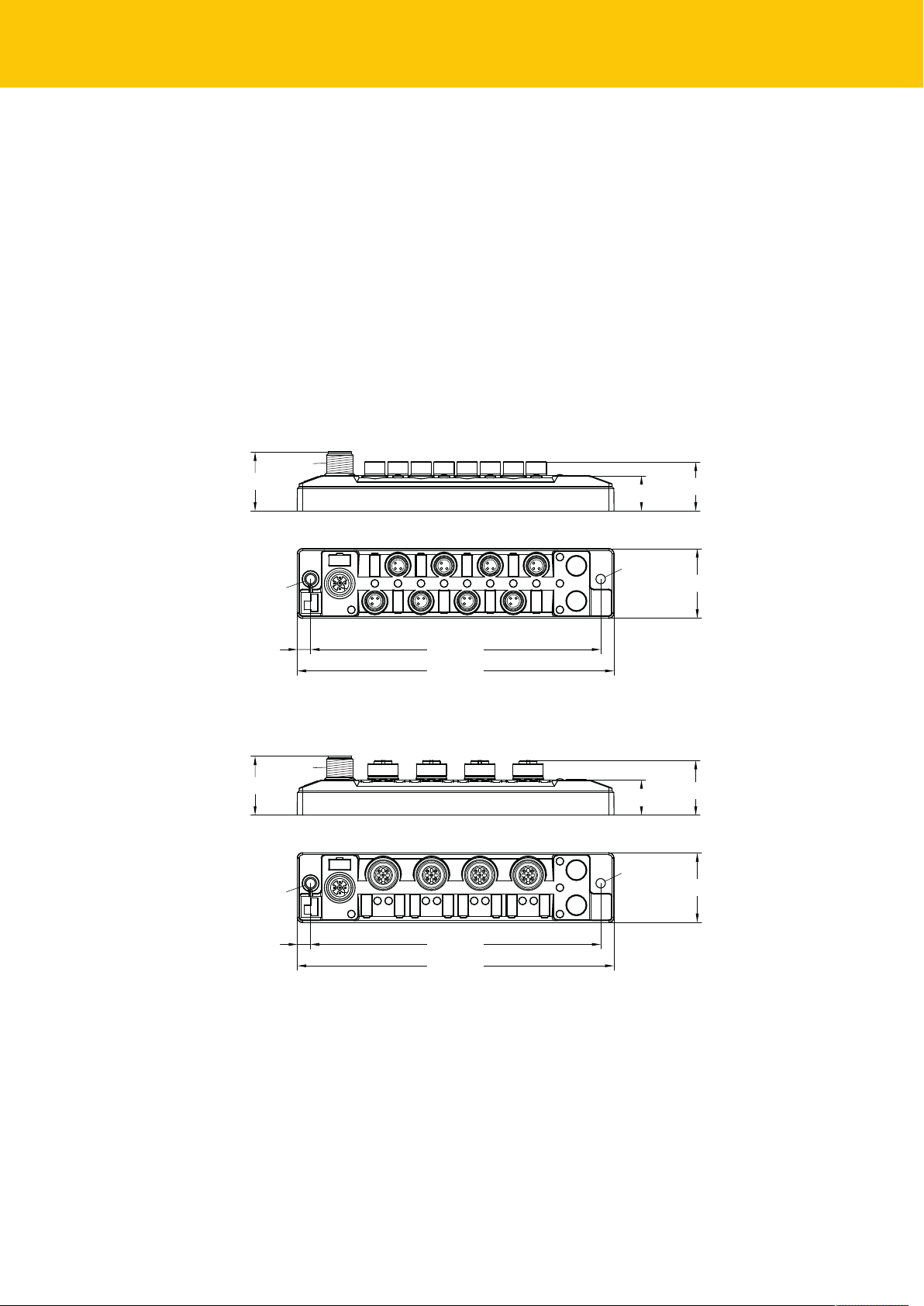
16 [0.63]
22.2 [0.87]
26.8 [1.06]
31.6 [1.24]
132 [5.20]6.1 [0.24]
144 [5.67]
M12 x 1
Ø 4.3 [0.17]
Ø 4.3 [0.17]
C3 C2
C7 C6
C1
C5
C0
C4
16 [0.63]
24.9 [0.98]
26.8 [1.06]
31.6 [1.24]
132 [5.20]6.1 [0.24]
144 [5.67]
M12 x 1
Ø 4.3 [0.17]
Ø 4.3 [0.17]
C3
C2 C1 C0
Device Overview
4 Product Description
The I/O hubs of the TBIL-S… series connect up to 8 digital sensors or up to sensors or actuators
with one IO-Link master port.
4 device types are available:
n TBIL-S3-8DIP: 8 digital input channels, 8 M8 connectors
n TBIL-S3-8DXP: 8 digital I/O, 8 M8 connectors, each channel can be used as digital in- or
output without additional configuration
n TBIL-S4-8DIP: 8 digital input channels, 4 M12 connectors
n TBIL-S4-8DXP: 8 digital I/O, 4 M12 connectors, each channel can be used as digital in- or
output without additional configuration
The devices are designed in a fully encapsulated housing with degree of protection IP67/IP69K.
4.1 Device Overview
Fig.1: Dimensions TBIL-S3-…
Fig.2: Dimensions TBIL-S4-…
4.1.1 Display Elements
The device has the following LED indicators:
n IO-Link communication
n I/O status
8
Hans Turck GmbH & Co. KG | T +49 208 4952-0 | F +49 208 4952-264 | more@turck.com | www.turck.com
Page 9

4.2 Properties and Features
n Fibre-glass reinforced housing
n Shock and vibration tested
n Fully potted module electronics
n Protection class IP67/IP69K
n IO-Link diagnostics for short-circuit and supply over- and undervoltage
n TBIL-S3-…: 1 digital input channel or 1 universal digital channel per M8 connector
TBIL-S4-…: 2 digital input channels or 2 universal digital channels per M12 connector
n metal connectors
4.3 Functions and Operating Modes
The I/O hubs with IO-Link of the TBIL-S series connect up to 8 digital sensors or 8 digital sensors
and actuators with one IO-Link master port.
The device provides diagnostics for power supply and short circuit of the sensors and actuators
on the IO-Link master.
V 01.01 | 2018/11
9
Page 10

Mounting
31.8
132
M4 (2 x)
max. 1.3 Nm
Grounding the device
5 Mounting
The device is mounted via four M4 screws on a flat and pre-drilled mounting surface.
Attach the module to the mounting surface with two M4 screws. The maximum tighten-
ing torque for the screws is 1.3 Nm
Fig.3: Mounting the device to a mounting surface (example: TBIL-S3-…)
5.1 Grounding the device
When mounting on a mounting plate, fasten the device with an M4 metal screw.
a The FE connection of the device is connected to the reference potential of the installation
via the M4 metal screw.
10
Hans Turck GmbH & Co. KG | T +49 208 4952-0 | F +49 208 4952-264 | more@turck.com | www.turck.com
Page 11
6 Connecting
4
13
2
5
1 = 24 VDC
2 = n.c.
3 = GND
4 = C/Q (IO-Link)
5 = n.c.
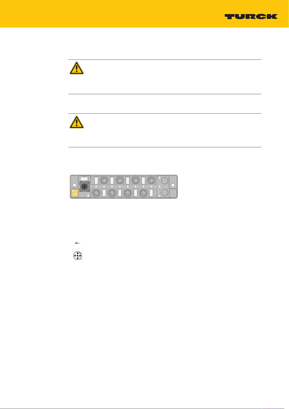
WARNING
Penetration of liquids or foreign objects through leaking connections
Danger to life due to malfunction
Fasten the M12 connectors with a tightening torque of 0.8 Nm.
Always seal unused connectors with respective protection caps.
6.1 Connecting the supply voltage and IO-Link
WARNING
Defective power supply unit
Danger to life due to dangerous voltages on touchable parts
Only use SELV or PELV power supplies in accordance with EN ISO 13849-2, which
allow a maximum of 60 VDC or 25 VAC in the event of a fault.
For the connection to IO-Link and the supply voltage, a 5-pole M12 connector is available.
Fig.4: M12 connector for the connection to IO-Link
Connect the device to the supply voltage and IO-Link according to the pin assignment.
Fig.5: Pin assignment IO-Link
V 01.01 | 2018/11
11
Page 12

Connecting
3 1
4
v
1 = V
AUX
3 = GND
4 = Signal In
C0…C7
3 1
4
v
1 = V
AUX
3 = GND
4 = Signal In/Out
C0…C7
Connecting Digital Sensors and Actuators
6.2 Connecting Digital Sensors and Actuators
Connecting Digital Sensors and Actuators – TBIL-S3-…
For connecting digital sensors and actuators, 3-pin M8 connectors are available.
Fig.6: TBIL-S3-…: M8 connector for connecting digital sensors and actuators
Connect the sensors to the device according to the pin assignment.
Fig.7: Pin assignment TBIL-S3-8DIP
Connect the sensors and actuators to the device according to the pin assignment.
Fig.8: Pin assignment TBIL-S3-8DIP
12
Hans Turck GmbH & Co. KG | T +49 208 4952-0 | F +49 208 4952-264 | more@turck.com | www.turck.com
Page 13

Connecting Digital Sensors and Actuators – TBIL-S4-…
4
1
3
2
5
v
1 = V
AUX
2 = Signal In
3 = GND
4 = Signal In
5 = FE
C0...C3
4
1
3
2
5
v
1 = V
AUX
2 = Signal In/Out
3 = GND
4 = Signal In/Out
5 = FE
C0...C3
For connecting digital sensors and actuators, 5-pin M12 connectors are available.
Fig.9: TBIL-S4-…: M12 connector for connecting digital sensors and actuators
Connect the sensors to the device according to the pin assignment.
Fig.10: Pin assignment TBIL-S4-8DIP
Connect the sensors and actuators to the device according to the pin assignment.
Fig.11: Pin assignment TBIL-S4-8DXP
V 01.01 | 2018/11
13
Page 14

Parameterizing an Configuring
Parameters
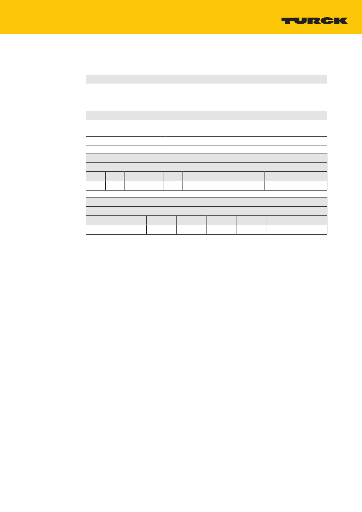
7 Parameterizing and Configuring
7.1 Parameters
IO-Link object directory – ISDU device parameters: Direct Parameter Page
ISDU
Index
Hex.
(Dec.)
0x00
(0)
Sub index Object name Access Length
[Byte]
Direct Parameter Page 1 read
only
0x07 Vendor ID read
0x08
0x09 Device ID read
0x0A
0x0B
only
only
16
2 0x013D
3 e.g. TBIL-S3-8DXP:
IO-Link object directory – ISDU device parameters: Identification
ISDU
Index
Hex.
(Dec.)
0x10
(16)
0x11
(17)
0x12
(18)
0x13
(19)
0x14
(20)
0x15
(21)
0x16
(22)
0x17
(23)
0x18
(24)
0x19
(25)
Object name Access Length
[Byte]
Vendor
Name
Vendor Text read
Product
Name
Product ID read
Product Text read
Serial
Number
Hardware ID read/
Firmware
Revision
Application
Specific Tag
Function Tag read/
read
only
only
read
only
only
only
read
only
write
read
only
read/
write
write
16 Turck
32 www.turck.com
32 e.g. TBIL-S3-8DXP
16 Ident no. of the device:
32 I/O hub
16 Sequential
8 Hardware ID of the
16 Firmware version of
32 Default "***" Customer-specific or
32 Default "***" The application-spe-
Meaning/
default value
e.g. 100002595 for
TBIL-S3-8DXP
serial number
device, e.g. V1.0
the device, e.g.
V1.0.7.0
Meaning/default value
(ID for Turck)
0x1E2213
Comment
application-specific
data can be stored in
this field.
cific device function
can be stored in this
field.
14
Hans Turck GmbH & Co. KG | T +49 208 4952-0 | F +49 208 4952-264 | more@turck.com | www.turck.com
Page 15

ISDU
Index
Object name Access Length
[Byte]
Meaning/
default value
Comment
Hex.
(Dec.)
0x1A
(26)
Location Tag read/
write
32 Default "***" The application-spe-
cific installation location of the device can
be stored in this field.
IO-Link object directory – ISDU device parameters: Preferred Index (parameters and
diagnostics of the digital in- and outputs)
ISDU
Index
Object name Access Length
Hex.
(dec.)
0x40
Parameter ID read/
(64)
0x41
(65)
0x42
(66)
0x43
(67)
Inverting
Input
Activate
Output
Impulse
Stretching
Input
0x44
(68)
0x45
Short Circuit
Recovery
Failsafe read/
(69)
0x46
(70)
Under
Voltage
Diagnostics
Diagnostics
0x50
Supply Error read
(80)
0x51
(81)
Output Short
Circuit
write
read/
write
read/
write
read/
write
read/
write
write
read/
write
only
read
only
Meaning
[Byte]
4 Customer-specific ID, for free use
1 Invert digital input
1 Activate output
only for TBIL-S…-8DXP
8 Pulse stretching input
1 Manual output reset after overcurrent
only for TBIL-S…-8DXP
2 Output After Error
only for TBIL-S…-8DXP
2 Undervoltage Diagnosis (defining the
threshold value for the undervoltag diagnostics)
2 n Over- and undervoltage supply
n Overcurrent V
connector C0…C7 or
AUX
C0…C3
1 Overcurrent output 0…7
only for TBIL-S…-8DXP
V 01.01 | 2018/11
15
Page 16

Parameterizing an Configuring
Parameters
Invert Digital Input – 0x41 (65), Sub Index 0
This parameter inverts the state of the digital input in the process image.
Format Length
Byte 1 byte 1 bit per channel
Default values are shown in bold.
Value Meaning
0 No
1 Yes Input signal inverted
n TBIL-S3-8DIP
n TBIL-S3-8DXP
Byte 0
Bit offset
7 6 5 4 3 2 1 0
C7P4 C6P4 C5P4 C4P4 C3P4 C2P4 C1P4 C0P4
n TBIL-S4-8DIP
n TBIL-S4-8DXP
Byte 0
Bit offset
7 6 5 4 3 2 1 0
C3P2 C3P4 C2P2 C2P4 C1P2 C1P4 C0P2 C0P4
NOTE
This parameter can also be set for all connectors of the module via the IODD.
16
Hans Turck GmbH & Co. KG | T +49 208 4952-0 | F +49 208 4952-264 | more@turck.com | www.turck.com
Page 17

Activate Output – 0x42 (66), Sub Index 0
this parameeter activates or deactivates the output function of the digital channel.
Format Length
Byte 1 byte 1 bit per channel
Default values are shown in bold.
Value Meaning
0 No Output function deactivated, channel can only be used as
input
1 Yes
n TBIL-S3-8DXP
Byte 0
Bit offset
7 6 5 4 3 2 1 0
C7P4 C6P4 C5P4 C4P4 C3P4 C2P4 C1P4 C0P4
n TBIL-S4-8DXP
Byte 0
Bit offset
7 6 5 4 3 2 1 0
C3P2 C3P4 C2P2 C2P4 C1P2 C1P4 C0P2 C0P4
Output function activated, channel can be used as in- or
output
NOTE
This parameter can also be set for all connectors of the module via the IODD.
V 01.01 | 2018/11
17
Page 18

Parameterizing an Configuring
Parameters
Pulse Stretching Input – 0×43 (67)
This parameter defines the duration of the pulse stretching for digital input edges in multiples
of 10 ms. This allows that even short signals with longer PLC cycle times can be detected.
Format Length
Array of Bytes 8 byte 1 byte per channel
Default values are shown in bold.
Value Meaning
0 disabled
1 1…255 Pulse stretching input [*10 ms]
n TBIL-S3-8DIP
n TBIL-S3-8DXP
Bit offset
0 8 16 24 32 40 48 56
Sub index
8 7 6 5 4 3 2 1
C7P4 C6P4 C5P4 C4P4 C3P4 C2P4 C1P4 C0P4
Pulse stretching deactivated
n TBIL-S3-8DIP
n TBIL-S3-8DXP
Bit offset
0 8 16 24 32 40 48 56
Sub index
16 15 14 13 12 11 10 9
C3P2 C3P4 C2P2 C2P4 C1P2 C1P4 C0P2 C0P4
NOTE
This parameter can also be set for all connectors of the module via the IODD.
18
Hans Turck GmbH & Co. KG | T +49 208 4952-0 | F +49 208 4952-264 | more@turck.com | www.turck.com
Page 19

Manual Output Reset after Overcurrent – 0x44 (68), Sub Index 0
This parameter defines if a manual reset is necessary after an overcurrent occurred at the digital
channel.
Format Length
Byte 1 byte 1 bit per channel
Default values are shown in bold.
Value Meaning
0 No
1 Yes Controlled recovery mode (output has to be reset manually)
n TBIL-S3-8DXP
Byte 0
Bit offset
7 6 5 4 3 2 1 0
C7P2 C6P4 C5P4 C4P4 C5P2 C2P4 C1P4 C0P4
n TBIL-S4-8DXP
Byte 0
Bit offset
7 6 5 4 3 2 1 0
C3P2 C3P4 C2P2 C2P4 C1P2 C1P4 C0P2 C0P4
Automatic recovery mode
NOTE
This parameter can also be set for all connectors of the module via the IODD.
V 01.01 | 2018/11
19
Page 20

Parameterizing an Configuring
Parameters
Output After Error – 0x45 (69), Sub Index 0
This parameter defines the behavior of the output in case of an interruption of the IO-Link communication.
Format Length
Array of Bytes 2 byte 2 bit per channel
Default values are shown in bold.
Value Meaning
00 0
01 1 Set output to 1
10 Current value Hold current value
11 reserved
n TBIL-S3-8DXP
Byte 1 Byte 0
Bit offset Bit offset
6 4 2 0 6 4 2 0
C7P4 C6P4 C5P4 C4P4 C3P4 C2P4 C1P4 C0P4
Set output to 0
n TBIL-S4-8DXP
Byte 1 Byte 0
Bit offset Bit offset
6 4 2 0 6 4 2 0
C3P2 C3P4 C2P2 C2P4 C1P2 C1P4 C0P2 C0P4
NOTE
This parameter can also be set for all connectors of the module via the IODD.
20
Hans Turck GmbH & Co. KG | T +49 208 4952-0 | F +49 208 4952-264 | more@turck.com | www.turck.com
Page 21
Undervoltage Diagnosis – 0x46 (70), Sub Index 0
This parameter defines threshold value for the undervoltage diagnostics.
Format Length
Array of Bytes 2 byte 1 bit per module
Default values are shown in bold.
Value Meaning
0 Standard
(IEC 61131-2)
1 Extended lower threshold: 17.5 V
Byte 0
Bit offset
7 6 5 4 3 2 1 0
- - - - - - - Threshold
Byte 1
Bit offset
7 6 5 4 3 2 1 0
- - - - - - - -
lower threshold: 19.2 V
upper threshold: 20.4 V
V 01.01 | 2018/11
21
Page 22

Operating
Process Input Data
8 Operating
8.1 Process Input Data
TBIL-S3-8DIP
Byte
no.
Inputs
0
Module diagnostics
1
Connector diagnostics – overcurrent sensor supply
2
TBIL-S3-8DXP
Byte
no.
Inputs
0
Module diagnostics
1
Connector diagnostics – overcurrent sensor supply
2
Channel diagnostics – overcurrent output
3
Bit offset
7 6 5 4 3 2 1 0
C7P4 C6P4 C5P4 C4P4 C3P4 C2P4 C1P4 C0P4
Group
diagnostics
Overcurrent
C7
Bit offset
7 6 5 4 3 2 1 0
C7P4 C6P4 C5P4 C4P4 C3P4 C2P4 C1P4 C0P4
Group
diagnostics
Overcurrent
C7
Overcurrent
C7P4
- - - - Undervoltage
Overcurrent
C6
- - - - Under-
Overcurrent
C6
Overcurrent
C6P4
Overcurrent
C5
Overcurrent
C5
Overcurrent
C5P4
Overcurrent
C4
Overcurrent
C4
Overcurrent
C4P4
Overcurrent
C3
Overcurrent
C3
Overcurrent
C3P4
Overcurrent
C2
voltage
Overcurrent
C2
Overcurrent
C2P4
- Overvoltage
Overcurrent
C1
- Over-
Overcurrent
C1
Overcurrent
C1P4
Overcurrent
C0
voltage
Overcurrent
C0
Overcurrent
C0P4
22
Hans Turck GmbH & Co. KG | T +49 208 4952-0 | F +49 208 4952-264 | more@turck.com | www.turck.com
Page 23

TBIL-S4-8DIP
Byte
no.
Inputs
0
Module diagnostics
1
Connector diagnostics – overcurrent sensor supply
2
TBIL-S4-8DXP
Byte
no.
Inputs
0
Module diagnostics
1
Connector diagnostics – overcurrent sensor supply
2
Channel diagnostics – overcurrent output
3
Bit offset
7 6 5 4 3 2 1 0
C3P2 C3P4 C2P2 C2P4 C1P2 C1P4 C0P2 C0P4
Group
dia-
- - - - Undervoltage
- Overvoltage
gnostics
- - - - Overcurrent
C3
Bit offset
7 6 5 4 3 2 1 0
Overcurrent
C2
Overcurrent
C1
Overcurrent
C0
C3P2 C3P4 C2P2 C2P4 C1P2 C1P4 C0P2 C0P4
Group
dia-
- - - - Undervoltage
- Overvoltage
gnostics
- - - - Overcurrent
C3
Overcurrent
C3P2
Overcurrent
C3P4
Overcurrent
C2P2
Overcurrent
C2P4
Overcurrent
C1P2
Overcurrent
C2
Overcurrent
C1P4
Overcurrent
C1
Overcurrent
C0P2
Overcurrent
C0
Overcurrent
C0P4
V 01.01 | 2018/11
NOTE
The diagnoses can also be accessed via IO-Link indices.
23
Page 24

Operating
Process Input Data
Designation Meaning
Inputs
CxPy 0 Input inactive
1 Input active
Module diagnostics
Group diagnostics 0 No diagnostic mes-
sage
1 Module diagnostics
active
undervoltage 0 No diagnostic message
1 Undervoltage of supply voltage
Overvoltage 0 No diagnostic message
1 Overvoltage of supply voltage
Connector diagnostics – overcurrent sensor supply
Overcurrent Cx 0 No diagnostic mes-
sage
1 Overload at the sensor supply at the connector.
The sensor/actuator supply is protected in groups. If an overload
occurs at one slot, all diagnostic bits of a group are active.
Groups:
n TBIL-S3-…: C0…C3, C4…C7
n TBIL-S4-…: C0…C1, C2…C3
Channel diagnostics – overcurrent output
Overcurrent CxPy 0 No diagnostic mes-
sage
1 Overlaod at the output/short-circuit
Evaluate the bit to monitor the dia-
gnostics cyclically.
ð Bit = 0: no diagnostics active
ð Bit = 1: Module diagnostics
Bit = 1: Evaluate further diagnostic
bits to determine the origin of the
diagnosctic message.
24
Hans Turck GmbH & Co. KG | T +49 208 4952-0 | F +49 208 4952-264 | more@turck.com | www.turck.com
Page 25

8.2 Process Output Data
TBIL-S3-8DXP
Byte
no.
Outputs
0
TBIL-S4-8DXP
Byte
no.
Outputs
0
Designation Meaning
CxPy 0 Output inactive
8.3 LED Displays
The device has the following LED indicators:
n IO-Link communication
n I/O status
Bit offset
7 6 5 4 3 2 1 0
C7P4 C6P4 C5P4 C4P4 C3P4 C2P4 C1P4 C0P4
Bit offset
7 6 5 4 3 2 1 0
C3P2 C3P4 C2P2 C2P4 C1P2 C1P4 C0P2 C0P4
1 Output active
8.3.1 IO-Link
IO-Link LED Meaning
Green flashing IO-Link communication error-free, valid process data are sent
Red IO-Link communication error or module error
Red flashing (1
Hz)
Off no voltage supply
8.3.2 Channel-LEDs
LED 0…7 Meaning (input) Meaning (output)
Green Input active Output active
Red flashing (0.5
Hz)
Red – Output active, overload/overcurrent
Off Input inactive Output inactive
IO-Link communication error-free, invalid process data or diagnostic message
Overload of the sensor supply
In devices with group diagnostics, all connector-LEDs of the supply group
flash simultaneously in case of an error.
at output
V 01.01 | 2018/11
25
Page 26

Operating
Evaluating Diagnostic Data
8.4 Evaluating Diagnostic Data
Group Diagnostics: Undervoltage and Overcurrent Sensor Supply – 0x50 (80), Sub Index0
Indicates errors in the module and sensor supply:
n Group diagnostics: Diagnostics pending at the module
n Over- or undervoltage, per module
n Overcurrent sensor supply V
Format Length
Array of Bytes 2 byte
0 = no diagnostics
1 = diagnostic message
Byte 0
Bit offset
15 14 13 12 11 10 9 8
Group diagnostics - - - - Undervoltage
, per connector
AUX
supply
- Overvoltage
supply
TBIL-S3-…
TBIL-S4-…
Byte 1
Bit offset
7 6 5 4 3 2 1 0
Overcurrent
V
C7
AUX
Byte 1
Bit offset
7 6 5 4 3 2 1 0
- - - - Over-
Overcurrent
V
C6
AUX
Overcurrent
V
C5
AUX
Overcurrent
V
C4
AUX
Overcurrent
V
C3
AUX
current
V
C3
AUX
Overcurrent
V
C2
AUX
Overcurrent
V
C2
AUX
Overcurrent
V
C1
AUX
Overcurrent
V
C1
AUX
Overcurrent
V
C0
AUX
Overcurrent
V
C0
AUX
26
Hans Turck GmbH & Co. KG | T +49 208 4952-0 | F +49 208 4952-264 | more@turck.com | www.turck.com
Page 27

Overcurrent Output – 0x51 (81), Sub Index 0
Indicates an overcurrent at the corresponding digital output.
Format Length
Byte 1 byte 1 bit per output
0 = no diagnostics
1 = diagnostic message
TBIL-S3-8DXP
Byte 0
Bit offset
7 6 5 4 3 2 1 0
Overcurrent
C7P4
Overcurrent
C6P4
Overcurrent
C5P4
Overcurrent
C4P4
TBIL-S4-8DXP
Byte 0
Bit offset
7 6 5 4 3 2 1 0
Overcurrent
C3P2
Overcurrent
C3P4
Overcurrent
C2P2
Overcurrent
C2P4
Overcurrent
C3P4
Overcurrent
C1P2
Overcurrent
C2P4
Overcurrent
C1P4
Overcurrent
C1P4
Overcurrent
C0P2
Overcurrent
C0P4
Overcurrent
C0P4
8.5 IO-Link Events
Event
Code
0x5110 Overvoltage
0x5111 Undervoltage
0x7710 Overcurrent V
Description Event Mode
0xF4 (appears) Supply voltage too high
supply
0xB4 (disappears)
0xF4 (appears) Supply voltage too low
supply
nector x
AUX
con-
0xB4 (disappears)
0xF4 (appears) Group event for Overcurrent:
0xB4 (disappears)
or
overcurrent output x
n Overcurrent of the sensor supply at
one of the connectors
or
n overcurrent at one of the outputs
(DO0…DO7)
The mapped diagnostics in the process
image of the inputs show which slot or
output detects an overcurrent.
V 01.01 | 2018/11
27
Page 28

Operating
IO-Link Error Codes
8.6 IO-Link Error Codes
Error code Description
0x8011 Index not available
0x8012 Sub Index not available
0x8023 Accesss denied Index cannot be written
0x8030 Parameter value out of range Parameter value out of range
0x8033 Parameter length overrun Length of data to be written does not
0x8034 Parameter length underrun
0x8035 Function not available Function not available in the device
0x8041 Inconsistent parameter set Inconsistent parameters
match the length defined for this parameter.
28
Hans Turck GmbH & Co. KG | T +49 208 4952-0 | F +49 208 4952-264 | more@turck.com | www.turck.com
Page 29

9 Troubleshooting
If the device does not function as expected, first check whether ambient interference is present.
If there is no ambient interference present, check the connections of the device for faults.
If there are no faults, there is a device malfunction. In this case, decommission the device and
replace it with a new device of the same type.
V 01.01 | 2018/11
29
Page 30

Maintenance
Returning Devices
10 Maintenance
Ensure that the plug connections and cables are always in good condition.
The devices are maintenance-free, clean dry if required.
11 Repair
The device must not be repaired by the user. The device must be decommissioned if it is faulty.
Observe our return acceptance conditions when returning the device to Turck.
11.1 Returning Devices
Returns can only be accepted if a declaration of decontamination is enclosed with the device.
The declaration can be downloaded from
http://www.turck.de/de/produkt-retoure-6079.php
and must be completely filled in, and affixed securely and weather-proof to the outside of the
packaging.
12 Disposal
The devices must be disposed of correctly and must not be included in normal
household garbage.
30
Hans Turck GmbH & Co. KG | T +49 208 4952-0 | F +49 208 4952-264 | more@turck.com | www.turck.com
Page 31

13 Technical Data
13.1 General Technical Data
Technical Data
Connectors
IO-Link M12, 5-pole
Input/output
n TBIL-S3-… M8, 3-pole
n TBIL-S4-… M12, 5-pole
Permissible torques
n IO-Link 0.8 Nm
n I/O channels M8: 0.4 Nm
n Mounting (M4 screws) 1.3 Nm
IO-Link
IO-Link specification Specified according to version 1.1
Parameterization FDT/DTM, IODD
Transmission rate COM 2: 38,4 kbit/s
Transmission physics Corresponds to 3-wire physics (PHY2)
Standard/Directive conformity
Vibration test According to EN 60068-2-6
Shock test According to EN 60068-2-27
Drop and topple According to IEC 60068-2-31/IEC 60068-2-32
Electro-magnetic compatibility According to EN 61131-2/-6-4
Approvals CE, cULus
General Information
Dimensions (w × l × h) 31,6 × 144 × 26,8 mm
Operating temperature -40…+70 °C
Storage temperature -40…+85 °C
Protection class IP67/IP69K
Housing material PA6-GF30
Housing color Black
Halogen-free Yes
Mounting 2 mounting holes, Ø 4,3 mm
M12: 0.6 Nm
V 01.01 | 2018/11
31
Page 32

Technical Data
TBIL-S…-8DIP
13.2 TBIL-S…-8DIP
Technical Data
Power supply
Operating/load voltage 18…30 VDC
Operating current < 90 mA
Sensor/actuator supply V
Total current max. 4 A per module
Inputs
Number of channels 8 digital pnp inputs (EN 61131-2)
Input voltage 18…30 VDC e.g. from supply voltage
Signal voltage, low level -3…5 VDC (EN 61131-2, type 1 and 3)
Signal voltage, high level 11…30 VDC (EN 61131-2, type 1 and 3)
Input delay 0.010 ms
Max. input current 15 mA
Potential isolation Inputs to FE, 500 VDC
IO-Link
Minimum cycle time 2.2 ms
AUX
Supply connectors C0…C7 or C…C3
0.5 A per channel group, short-circuit protected with diagnostics
channel groups:
n TBIL-S3-8DIP: C0…C3, C4…C7
n TBIL-S4-8DIP: C0…C1, C2…C3
32
Hans Turck GmbH & Co. KG | T +49 208 4952-0 | F +49 208 4952-264 | more@turck.com | www.turck.com
Page 33

13.3 TBIL-S…-8DXP
Technical Data
Power supply
Operating/load voltage 18…30 VDC
Operating current < 90 mA
Sensor/actuator supply V
Total current max. 4 A per module
Inputs
Number of channels 8 digital pnp inputs (EN 61131-2)
Input voltage 18…30 VDC e.g. from supply voltage
Signal voltage, low level -3…5 VDC (EN 61131-2, type 1 and 3)
Signal voltage, high level 11…30 VDC (EN 61131-2, type 1 and 3)
Input delay 0.010 ms
Max. input current 15 mA
Potential isolation Inputs to FE, 500 VDC
Outputs
Number of channels 8 digital pnp outputs
Type of output diagnostics Channel diagnostics
Output voltage 24 VDC from supply voltage
Output current per channel 0.5 A, short-circuit-proof
Output delay 0.15 ms
Load type Ohmic, inductive lamp load
Potential isolation Outputs to FE, 500 VDC
IO-Link
Minimum cycle time 2.8 ms
AUX
Supply connectors C0…C7 or C…C3
0.5 A per channel group, short-circuit protected with diagnostics
channel groups:
n TBIL-S3-8DIP: C0…C3, C4…C7
n TBIL-S4-8DIP: C0…C1, C2…C3
V 01.01 | 2018/11
33
Page 34

Appendix
EU-Konformitätserklärung Nr.: 5035-2M
EU Declaration of Conformity No.:
Wir/ We: HANS TURCK GMBH & CO KG
WITZLEBENSTR. 7, 45472 MÜLHEIM A.D. RUHR
erklären in alleiniger Verantwortung, dass die Produkte
declare under our sole responsibility that the products
Kompakte I/O Module in IP20/IP67:
Compact I/O modules in
IP20/IP67:
Typen / types: FDN20-*, FDNL-*, FDNP-*, FDP20-*, FGDP-*, FGEN-*,
FLDP-*, FLIB-*, FXEN-*, SDPX-*, TBDP-*, TBEN-*, TBIL-*, TBPN-*
auf die sich die Erklärung bezieht, den Anforderungen der folgenden EU-Richtlinien durch Einhaltung der
folgenden Normen genügen:
to which this declaration relates are in conformity with the requirements of the following EU-directives by compliance with the following
standards:
EMV - Richtlinie /EMC Directive 2014 / 30 / EU 26.02.2014
EN 61131-2:2007 (Abschnitte / section 8, 9, 10)
RoHS – Richtlinie /RoHS Directive 2011 / 65 / EU 08.06.2011
Weitere Normen, Bemerkungen:
additional standards, remarks:
Zusätzliche Informationen:
Supplementary infomation:
Mülheim, den 13.07.2018
i.V. Dr. M. Linde, Leiter Zulassungen /Manager Approvals
Ort und Datum der Ausstellung / Name, Funktion und Unterschrift des Befugten /
Place and date of issue Name, function and signature of authorized person
14 Appendix: Declaration of Conformity
34
Hans Turck GmbH & Co. KG | T +49 208 4952-0 | F +49 208 4952-264 | more@turck.com | www.turck.com
Page 35

100003857 | 2018/11
Over 30 subsidiaries and over
60 representations worldwide!
100003857
www.turck.com
 Loading...