

Page 1

TM
TBEN-LG EtherNet/IP
Configuration Guide
Date: 03.20.2015
Version: 1.4
TURCK Inc.
Page 2

TBEN-LG EtherNet/IP
TM
Configuration Guide
TURCK • 3000 Campus Drive • Minneapolis, MN 55441-2656 2
Phone: 763.553.7300 • Toll Free: 800.544.7769 • Fax: 763.553.0708 • www.turck.us
Page 3

TBEN-LG EtherNet/IP
TM
Configuration Guide
Table of Contents
Table of Contents ..................................................................................................................... 3
Introduction ........................................................................................................................... 5
TBEN-LG ................................................................................................................................... 7
TBEN-LG Product Line .......................................................................................................... 7
Part Numbers ................................................................................................................... 7
Connection Diagrams ....................................................................................................... 8
LED Diagnostics ...................................................................................................................11
Ethernet Ports and Device Fault LEDs .............................................................................12
Power LED ......................................................................................................................13
IO LEDs TBEN-LG-16DIP ................................................................................................14
IO LEDs TBEN-LG-16DOP ..............................................................................................14
IO LEDs TBEN-LG-8DIP-8DOP .......................................................................................15
IO LEDs TBEN-LG-16DXP ..............................................................................................15
IO Data Format.....................................................................................................................16
TBEN-LG-16DIP ..............................................................................................................16
TBEN-LG-8DIP-8DOP .....................................................................................................17
TBEN-LG-16DOP ............................................................................................................17
TBEN-LG-16DXP .............................................................................................................18
Setting up IP Address ...........................................................................................................19
Address Switches in Static Rotary ...................................................................................19
BOOTP/DHCP Mode (300/400) .......................................................................................20
Note: ................................................................................................................................20
When the device is set to 500 (PGM) mode, its IP address can be further changed using
either the IP Address Tool or WEB page. ........................................................................20
PGM-DHCP Mode (600) ..................................................................................................21
Note: ................................................................................................................................21
When the device is set to 600 (PGM-DHCP) mode, its IP address can be further changed
using either the IP Address Tool or WEB page. ...............................................................21
PGM Mode (500, 600) .....................................................................................................22
PGM (500) and Web Server.............................................................................................22
IP Address Tool ...............................................................................................................24
PGM (500) and IP address tool ........................................................................................25
Restore Mode (0) .............................................................................................................27
Factory Reset Mode (900) ...............................................................................................27
TBEN EtherNet/IP Configuration ............................................................................................28
TBEN Configuration Using EDS Files ...................................................................................28
Configure EtherNet/IP User Interface ...............................................................................29
Create RSLogix5000 Project............................................................................................30
Install EDS File(s) ............................................................................................................31
Create new TBEN Module ...............................................................................................33
Configure Connection and data format ............................................................................36
Module Definition Data Format ........................................................................................37
TURCK • 3000 Campus Drive • Minneapolis, MN 55441-2656 3
Phone: 763.553.7300 • Toll Free: 800.544.7769 • Fax: 763.553.0708 • www.turck.us
Page 4

TBEN-LG EtherNet/IP
TM
Configuration Guide
TBEN Data Tags ..............................................................................................................38
TBEN-LG Configuration Parameters ................................................................................40
Configuration Assembly Data Structure ...........................................................................41
TBEN-LG Profile Info .......................................................................................................45
TBEN Configuration Using Generic Device ..........................................................................46
Configure TBEN-LG-16DIP ..............................................................................................47
Configure TBEN-LG-16DOP ............................................................................................47
Configure TBEN-LG-8DIP-8DOP .....................................................................................48
Configure TBEN-LG-16DXP ............................................................................................48
Configure Connection ......................................................................................................49
TBEN Web Server ...............................................................................................................50
Home Page ......................................................................................................................50
Login / password ..............................................................................................................51
Network Configuration .....................................................................................................52
Station Configuration .......................................................................................................53
Station Diagnostics ..........................................................................................................54
Ethernet Statistics ............................................................................................................54
IO Parameters .................................................................................................................55
TURCK • 3000 Campus Drive • Minneapolis, MN 55441-2656 4
Phone: 763.553.7300 • Toll Free: 800.544.7769 • Fax: 763.553.0708 • www.turck.us
Page 5

TBEN-LG EtherNet/IP
TM
Configuration Guide
Introduction
The guide provides information about device features, connection diagrams and LED diagnostics.
It also shows how to set up device IP address using different tools. TBEN-LG devices can be configured
with EDS files, or using a generic device profile. Device web server provides advanced configurati on and
diagnostics information. TURCK IP address tool is used for quick discovery of TURCK devices residing
on different VLANS.
The guide, together with the data sheets, provides sufficient information for using TBEN in DLR
(device level ring) or QC (quick connect) applications. DLR application does not require any specific device setup, as devices are ready for DLR networks. QC mat be enabled or disabled by a single configuration bit, part of configuration data tag. Address conflict detection (ADC) is implemented and enabled in
the device by default. TBEN supports up to 3 TCP connections and 6 CIP connections, and it may be
configured with 3 PLCs using Exclusive Owner, Input only or Listen Only connections.
TURCK • 3000 Campus Drive • Minneapolis, MN 55441-2656 5
Phone: 763.553.7300 • Toll Free: 800.544.7769 • Fax: 763.553.0708 • www.turck.us
Page 6

TBEN-LG EtherNet/IP
TM
Configuration Guide
TURCK • 3000 Campus Drive • Minneapolis, MN 55441-2656 6
Phone: 763.553.7300 • Toll Free: 800.544.7769 • Fax: 763.553.0708 • www.turck.us
Page 7
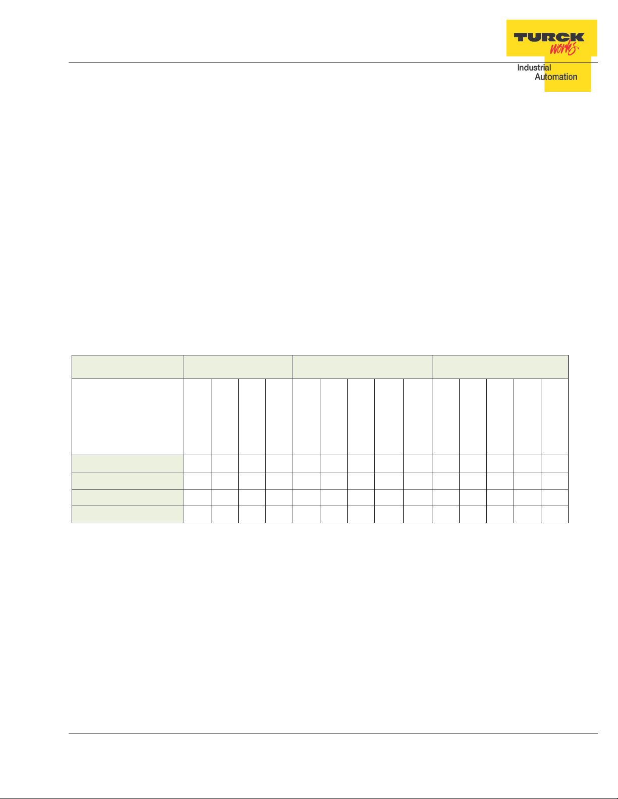
Number of
inputs Input type
Inputs per con-
nector PNP / NPN type
Number of
outputs Output type
outputs per
connector Maximum out-
put load Short circuit
protection Ethernet ports
Configuration
Assembly DLR QC ACD
#1
2
2
2
TBEN-LG EtherNet/IP
TM
Configuration Guide
TBEN-LG
TBEN-LG Product Line
The TBEN-LG series are multiprotocol communication adapters and they support Modbus
TCP/IP, EtherNet/IP and PROFINET communication protocols. All protocols are enabled “outof-box” by default. After power up, a multiprotocol station queries all necessary ports to detect
what protocol is used. The “Active Fieldbus Protocol” is defined as the first protocol to do one of
the following actions:
− Modbus TCP Write to output register range.
− EtherNet/IP Establish Class 1 Exclusive Owner connection to device.
− PROFINET Connect request.
This “Configuration Guide” shows TBEN-LG-8DIP-8DOP in an EtherNet/IP environment to describe features and configuration procedures of the TBEN-LG series.
Part Numbers
Part Number Input description Output description Ethernet
TBEN-LG-16DIP
TBEN-LG-16DOP
TBEN-LG-16DXP
TBEN-LG-8DIP-8DOP
16 2S 2 PNP
16 2G 2 1A
16 2X 2 PNP 16 2X 2 1A
8 2S 2 PNP 8 2G 2 1A
#2
✔
✔
✔
✔
2
Key:
2S: Two PnP inputs per connector
2X: Dual combined input/output per connector, PNP / 1A
2G: Two outputs per connector, 1A each
#1: 2A output when single output per connector is used
#2: Inputs protected per connector; outputs are individually protected
DLR Device Level Ring
QC Q uick Connect; QC time 100msec
ACD Address Conflict Detection and resolution
✔ ✔ ✔ ✔
✔ ✔ ✔ ✔
✔ ✔ ✔ ✔
✔ ✔ ✔ ✔
TURCK • 3000 Campus Drive • Minneapolis, MN 55441-2656 7
Phone: 763.553.7300 • Toll Free: 800.544.7769 • Fax: 763.553.0708 • www.turck.us
Page 8

Ethernet
M12, d-coded
IN
M12, a-coded
TBEN-LG EtherNet/IP
TM
Connection Diagrams
Configuration Guide
Device Type
TBEN-LG-16DIP
1 = TD+ 1 = RD+
2 = RD+ 2 = TD+
3 = TD- 3 = RD 4 = RD- 4 = TD-
(see „Note 1“)
P1 P2
Power (7/8“)
C0 … C7
1 = VAUX1 (+)
2 = Second input
3 = V1 (-)
4 = First input
5 = FE
(see „Note 2“)
TURCK • 3000 Campus Drive • Minneapolis, MN 55441-2656 8
Phone: 763.553.7300 • Toll Free: 800.544.7769 • Fax: 763.553.0708 • www.turck.us
Page 9
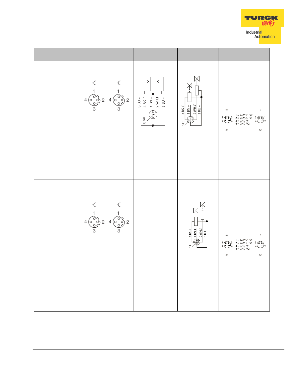
Ethernet
M12, d-coded
IN
M12, a-coded
Out
M12, a-coded
TBEN-LG EtherNet/IP
TM
Configuration Guide
Device Type
TBEN-LG-8DIP-8DOP
P1 P2
1 = TD+ 1 = RD+
2 = RD+ 2 = TD+
3 = TD- 3 = RD 4 = RD- 4 = TD-
(see „Note 1“)
C0 … C3
1 = VAUX1 (+)
2 = Second input
3 = V1 (-)
4 = First input
5 = FE
1 = VAUX2 (+)
2 = Second output
3 = V2 (-)
4 = First output
5 = FE
C4 … C7
Power (7/8“)
TBEN-LG-16DOP
P1 P2
1 = TD+ 1 = RD+
2 = RD+ 2 = TD+
3 = TD- 3 = RD 4 = RD- 4 = TD-
(see „Note 1“)
C0 … C7
1 = VAUX2 (+)
2 = Second output
3 = V2 (-)
4 = First output
5 = FE
TURCK • 3000 Campus Drive • Minneapolis, MN 55441-2656 9
Phone: 763.553.7300 • Toll Free: 800.544.7769 • Fax: 763.553.0708 • www.turck.us
Page 10
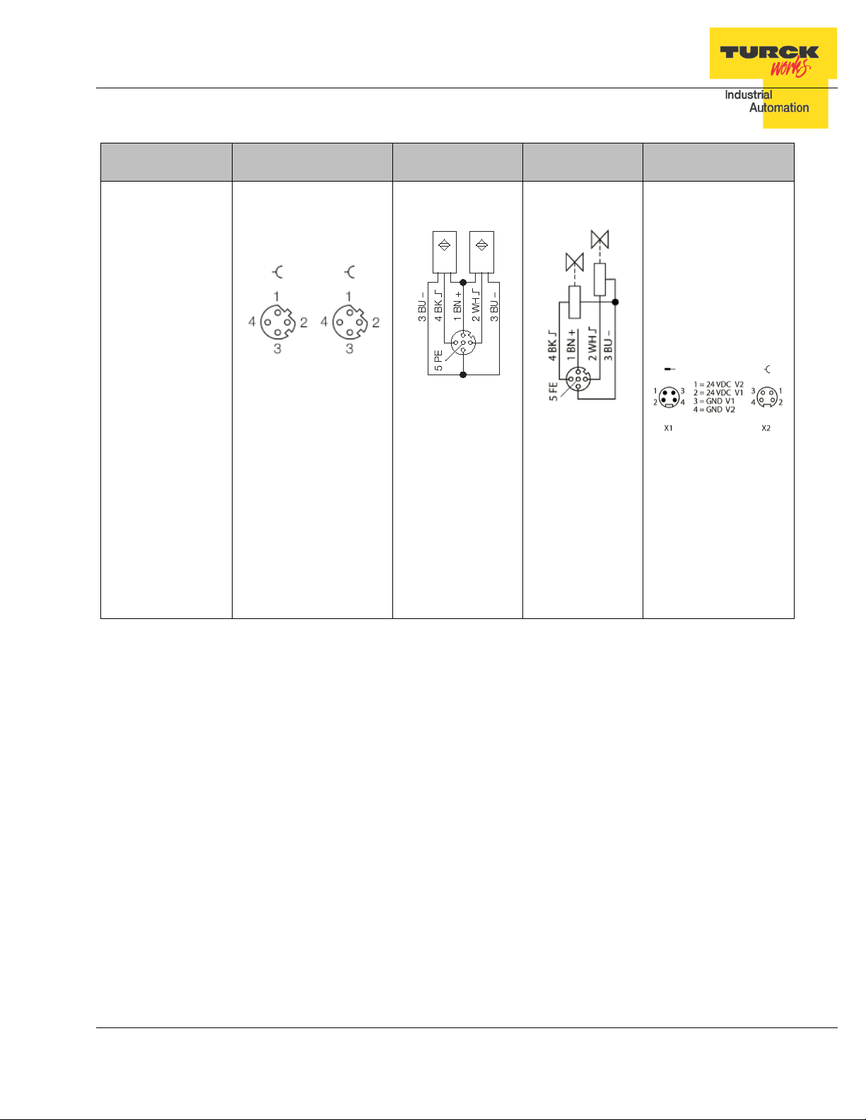
Ethernet
IN
Out
TBEN-LG EtherNet/IP
TM
Configuration Guide
Device Type
TBEN-LG-16DXP
M12, d-coded
P1 P2
1 = TD+ 1 = RD+
2 = RD+ 2 = TD+
3 = TD- 3 = RD 4 = RD- 4 = TD(see „Note 1“)
M12, a-coded
M12, a-coded
Power (7/8“)
C0 … C7
1 = VAUX1 (+)
2 = Second input
3 = V1 (-)
4 = First input
5 = FE
DXP allows for any
combination of IO per
single connector
C0 … C7
1 = VAUX2 (+)
2 = Second output
3 = V2 (-)
4 = First output
5 = FE
Note 1:
The pin-out of P1 and P2 are “crossed over”. P1 has a “NIC-Type” connection and P2 has a “Switch-
Type” connection. The TBEN devices are configured with Auto-MDIX enabled when not used for fast
startup / quick connect. In that case the switch detects the cabling type itself.
With the crossed connection of P2 it is possible to connect multiple devices in a row without Auto-MDIX
with 1:1 EtherNet cables. This ensures that the switch could establish a link quickly for fast start-up devices.
Note 2:
VAUX1 = V1 – 0.2 VDC (voltage drop over protective circuit)
VAUX2 = V2 – 0.2 VDC (voltage drop over protective circuit)
TURCK • 3000 Campus Drive • Minneapolis, MN 55441-2656 10
Phone: 763.553.7300 • Toll Free: 800.544.7769 • Fax: 763.553.0708 • www.turck.us
Page 11
TBEN-LG EtherNet/IP
TM
Configuration Guide
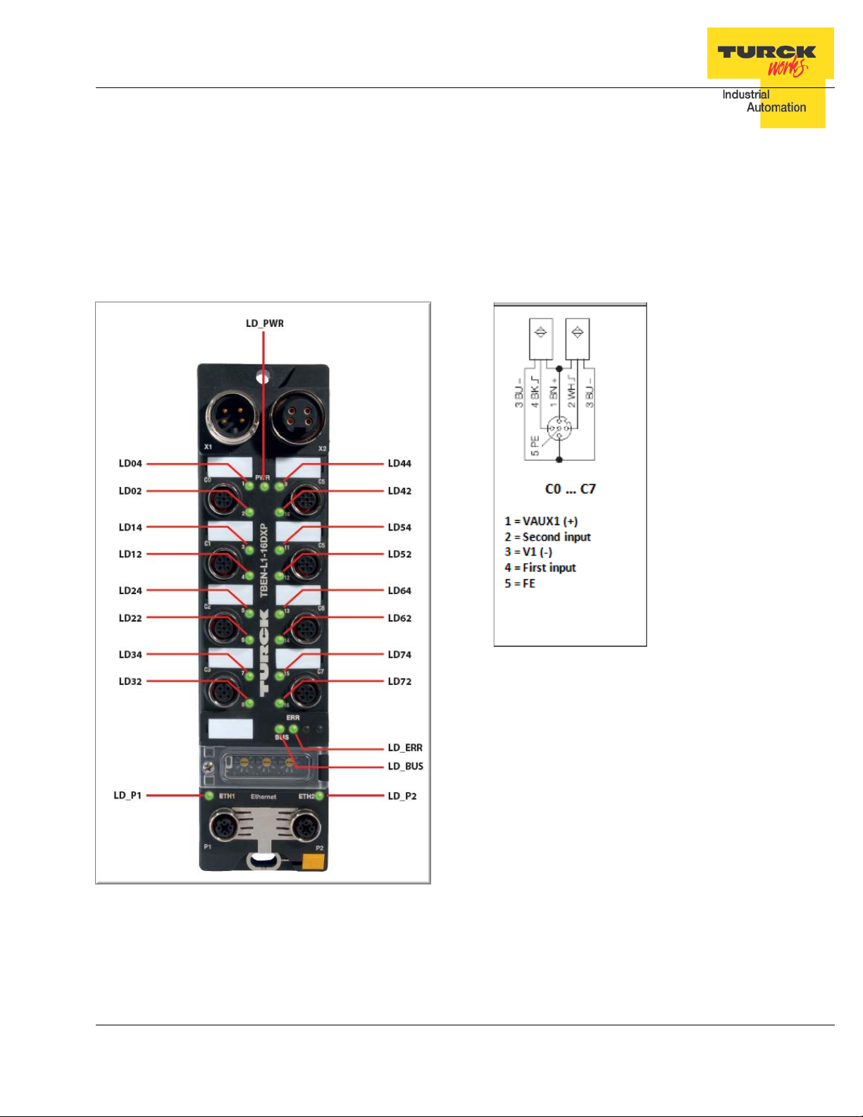
LED Diagnostics
The notation of the IO LEDs (LD04 … LD72) is “LDxy”. I t is linked to the appropriate channel
and is coded as follows:
LDxy key:
− x: connector number: 0, 1,…, 7 (C0, C1, …, C7)
− y: signal pin number of the appropriate connector ( 2, 4)
− LD24: connector 2, pin 4
TURCK • 3000 Campus Drive • Minneapolis, MN 55441-2656 11
Phone: 763.553.7300 • Toll Free: 800.544.7769 • Fax: 763.553.0708 • www.turck.us
Page 12
alternating
TBEN-LG EtherNet/IP
TM
Configuration Guide
Ethernet Ports and Device Fault LEDs
LED Status Description
LD_P1 and LD_P2 (same functionality for all device types)
off No Ethernet link
LD_P1 , LD_P2 green on Link 100MBit. The LED flashes during data transfer.
( yellow / green ) yellow o n Link 10MBit. The LED flashes during data transfer.
yellow on / green on Not valid state
LD_BUS (same functionality for all device types)
off No supply voltage
green on Active connect ion to a master
LD_BUS green blinking Ready for operation
( red / green ) red on
red on / green on
LD_ERR (same functionality for all device types)
LD_ERR green on Normal operation
( red / green ) red on Diagnostics active
red on / green on Not valid state
IP address conflict is detected or restore mode (0 /
900 switch position),
red flashing
off No supply voltage
Blink / Wink is active (command sent from the IO
assistant, IP address tool)
Auto-negotiation and/or DHCP/BOOTP waiting for IP
address assignment
TURCK • 3000 Campus Drive • Minneapolis, MN 55441-2656 12
Phone: 763.553.7300 • Toll Free: 800.544.7769 • Fax: 763.553.0708 • www.turck.us
Page 13
LD-PWR (device powered by V1 only)
TBEN-LG-16DIP
LD_PWR (device powered by V1 and V2)
TBEN-LG-8DIP-8DOP
TBEN-LG-16DOP
TBEN-LG-16DXP
V1 power on
V2 power off or undervoltage < 18V
TBEN-LG EtherNet/IP
Power LED
LED Status Description
TM
Configuration Guide
LD_PWR
( green )
LD_PWR
( green )
off V1 power off or undervoltage < 18V
on V1 and V2 power on
off V1 power off or undervoltage < 18V
green on V1 and V2 power on
flashing
TURCK • 3000 Campus Drive • Minneapolis, MN 55441-2656 13
Phone: 763.553.7300 • Toll Free: 800.544.7769 • Fax: 763.553.0708 • www.turck.us
Page 14
Input Channel I0,…,I15 LEDs
Channel LEDs: LD02 … LD74 (Channel CH02 … Channel CH74)
LD72
4
LD72
4
off
Output inactive
TBEN-LG EtherNet/IP
TM
Configuration Guide
IO LEDs TBEN-LG-16DIP
LED Status Description
TBEN-LG-16DIP
off Input inactive
LD02,...,
LD04,…,LD7
( red / green )
IO LEDs TBEN-LG-16DOP
LED Status Description
Channel LEDs: LD02 … LD74 (Channel CH02 … Channel CH74)
LD02,...,
LD04,…,LD7
( red / green )
green on Input active
red flashing
Power overload at the connector “x”, both LEDs of
the input channels CHx2 and CHx4 are flashing.
Output Channel O0,…,O15 LEDs
TBEN-LG-16DOP
green on Output ac ti ve
red on
Power overload at the corresponding output channel CHxy
TURCK • 3000 Campus Drive • Minneapolis, MN 55441-2656 14
Phone: 763.553.7300 • Toll Free: 800.544.7769 • Fax: 763.553.0708 • www.turck.us
Page 15
LD12, LD14,
LD62, LD64,
LD72, LD74,
LD02,...,LD72
4
Power overload at the corresponding output
channel CHxy.
Output channel CH22 active (solid green / flashing
TBEN-LG EtherNet/IP
TM
Configuration Guide
IO LEDs TBEN-LG-8DIP-8DOP
LED Status Description
Channel LEDs: LD02 … LD34 (Channel CH02 … Channel CH34)
Input Channel I0,…,I7 LEDs
TBEN-LG-8DIP-8DOP
LD02, LD04,
LD22, LD24,
LD32, LD34,
( red / green )
Channel LEDs: LD42 … LD74 (Channel CH42 … Channel CH74)
LD42, LD44,
LD52, LD54,
( red / green )
IO LEDs TBEN-LG-16DXP
LED Status Description
Channel LEDs: LD02 … LD74 (Channel CH02 … Channel CH74)
off Input inactive
green on Input active
red flashing
Power overload at the connector “x”, both LEDs of
the input channels CHx2 and CHx4 are flashing.
Output Channel O0,…,O7 LEDs
TBEN-LG-8DIP-8DOP OUTPUTS
off Output inactive
green on Output ac ti ve
red on
Power overload at the corresponding output
channel CHxy.
IO Channel IO0,…,IO15 LEDs
TBEN-LG-16DXP
2 x red flashing
LD04,…,LD7
( red / green )
green on / flashing red
TURCK • 3000 Campus Drive • Minneapolis, MN 55441-2656 15
Phone: 763.553.7300 • Toll Free: 800.544.7769 • Fax: 763.553.0708 • www.turck.us
off IO inactive (input or output)
green on IO active (input or output)
Power overload at the connector “x”, both LEDs of
the input channels CHx2 and CHx4 are flashing.
red on
red).
e.g. LD22
Power overload at the input channel CH24 (flashing
red)
Page 16
TBEN-LG EtherNet/IP
TM
Configuration Guide
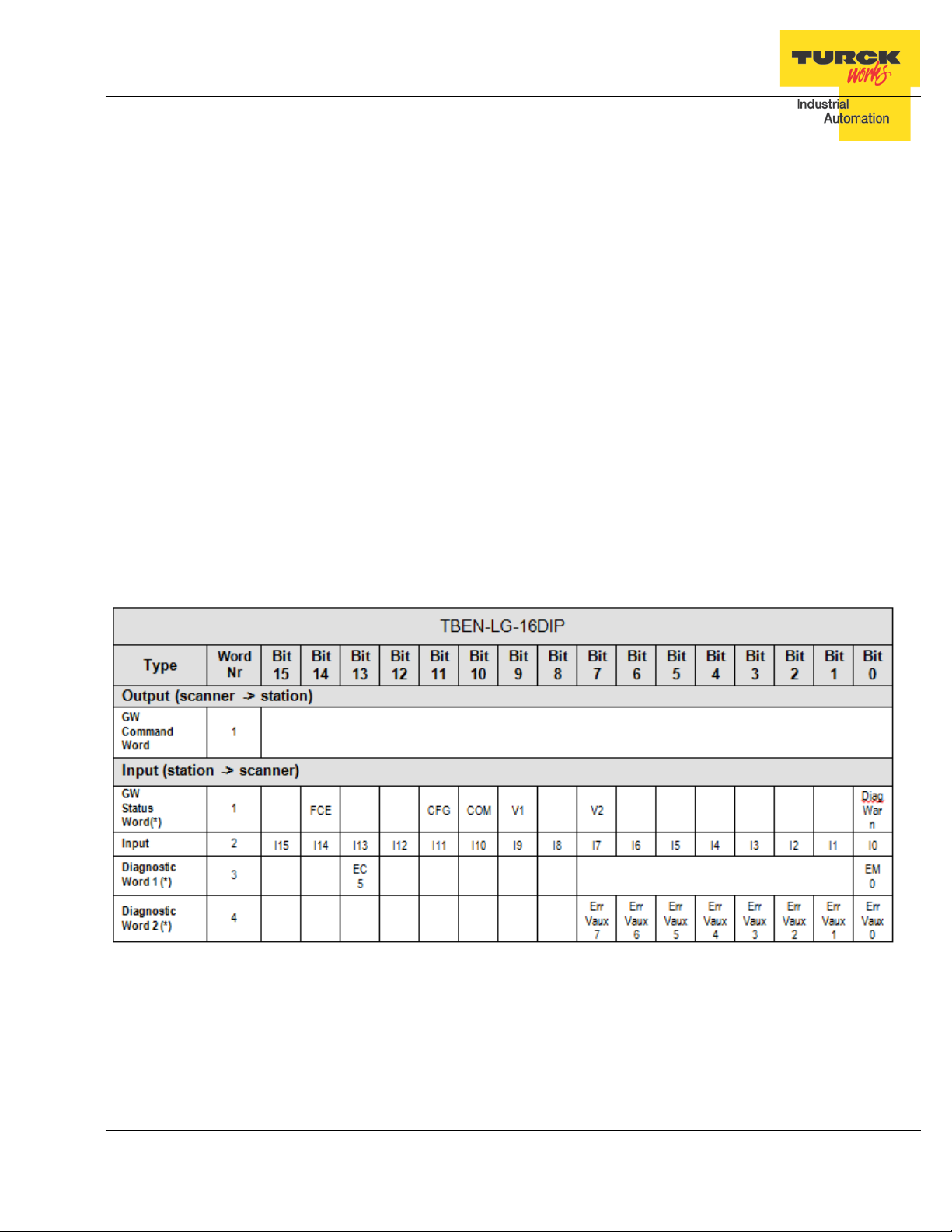
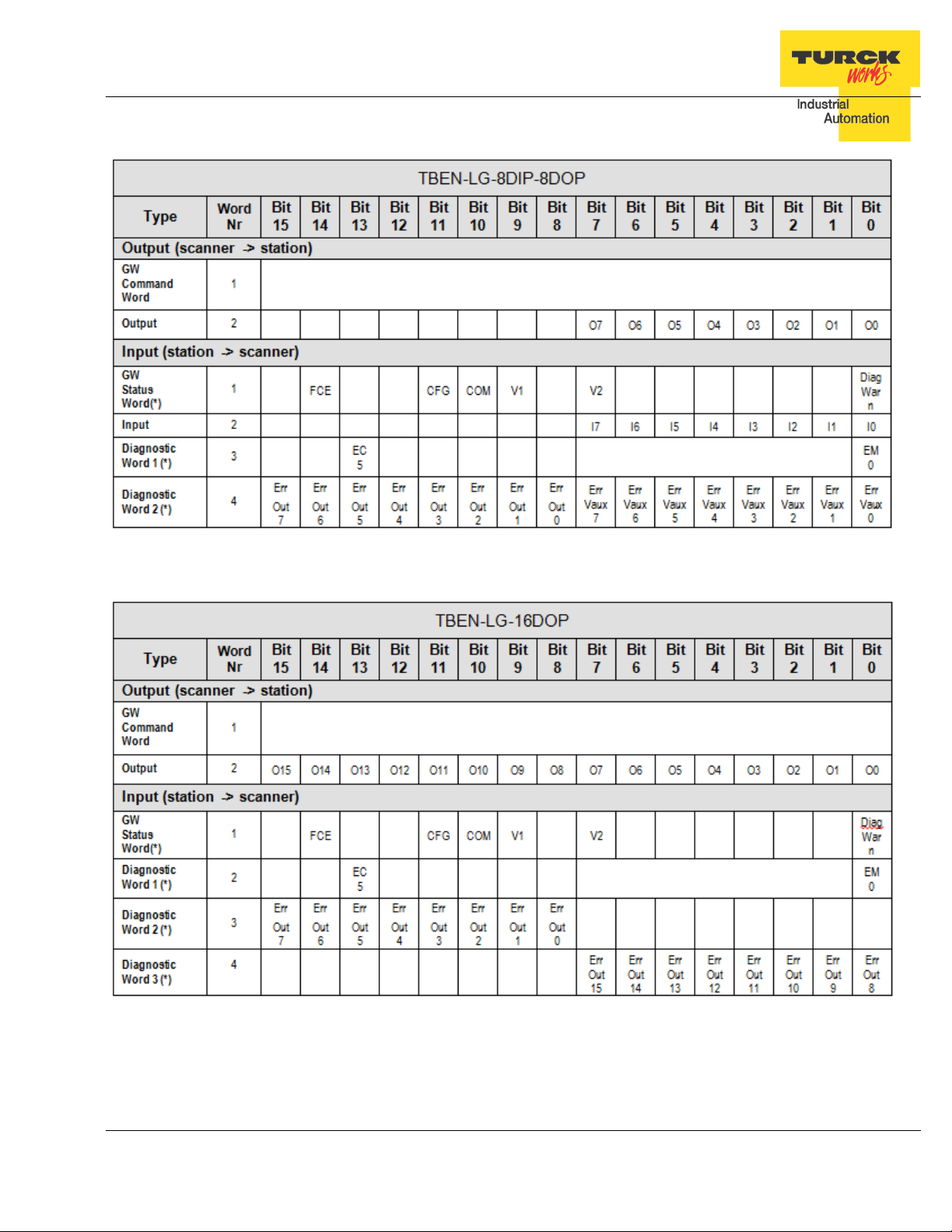
IO Data Format
Abbreviations:
I0…I15: Inputs
O0…O15: Outputs
FCE: Force mode active
CFG: I/O configuration error
COM: Communication lost on the internal bus
V1: V1 too low
V2: V2 too low
DiagWarn: Summarized diagnostic of the device
EM0: Summarized diagnostic of the device
ECx : Error Code bit x in error-code bit area
SRO0…15: Short circuit recovery mode of outputs 0…15
Err Vaux0…7: Auxiliary supply error on connector 0…7
Err Out0…15: Short circuit output 0…15
Inv.I0…I15: Inverted input signal 0…15
TBEN-LG-16DIP
Note: a blank field means reserved or not used.
TURCK • 3000 Campus Drive • Minneapolis, MN 55441-2656 16
Phone: 763.553.7300 • Toll Free: 800.544.7769 • Fax: 763.553.0708 • www.turck.us
Page 17
TBEN-LG EtherNet/IP
TM
TBEN-LG-8DIP-8DOP
Configuration Guide
TBEN-LG-16DOP
TURCK • 3000 Campus Drive • Minneapolis, MN 55441-2656 17
Phone: 763.553.7300 • Toll Free: 800.544.7769 • Fax: 763.553.0708 • www.turck.us
Page 18

TBEN-LG EtherNet/IP
TBEN-LG-16DXP
TM
Configuration Guide
TURCK • 3000 Campus Drive • Minneapolis, MN 55441-2656 18
Phone: 763.553.7300 • Toll Free: 800.544.7769 • Fax: 763.553.0708 • www.turck.us
Page 19

TBEN-LG EtherNet/IP
TM
Configuration Guide
Setting up IP Address
TBEN has three rotary switches which are used to set either the last octet of the device IP address or device mode of operation. Valid address range and mode of operation are:
The address switches are pre-set out of box to 600 (PGM-DHCP mode). IP address can be assigned immediately using DHCP server.
General procedure for IP address setup is:
− Set rotary switches to desired mode (300, 400, 500, 600)
− Cycle power to the station
− Run IP address utility to assign IP address
− Set address switches to static rotary position or PGM mode
− Cycle power to the station
The TBEN station IP address can be configured and/or changed in following ways:
− Using static rotary mode
− BootP Server utility
− DHCP Server utility
− TBEN Web page
− IP Address tool
Address Switches in Static Rotary
When address switches are in static mode, the last octet may be dialed in 1-254 range.
Addresses 0 and 255 are reserved and cannot be used.
Following example shows the last octet set to of address xx.xxx.xxx.173
Setting rotary switches to any other position not listed on the device or data sheet sets device
into DHCP mode and bus LED flashes green / red.
TURCK • 3000 Campus Drive • Minneapolis, MN 55441-2656 19
Phone: 763.553.7300 • Toll Free: 800.544.7769 • Fax: 763.553.0708 • www.turck.us
Page 20

TBEN-LG EtherNet/IP
TM
Configuration Guide
BOOTP/DHCP Mode (300/400)
The TBEN rotary switches, when set to 300 or 400, allow for IP address assignment as follows:
− Set the rotary switches to 300 to enable BOOTP mode and power cycle the device
− Set the rotary switches to 400 to enable DHCP mode and power cycle the device
− Run BOOTP or DHCP utility and assign IP address
− Set the rotary switches either to 500 (PGM mode) or to a number that matches the last
octet of the assigned IP address (e.g. 125)
− Power cycle the device
Note: When the device is set to 500 (PGM) mode, its IP address can be further changed using either the IP Address Tool or WEB page.
TURCK • 3000 Campus Drive • Minneapolis, MN 55441-2656 20
Phone: 763.553.7300 • Toll Free: 800.544.7769 • Fax: 763.553.0708 • www.turck.us
Page 21

TBEN-LG EtherNet/IP
TM
Configuration Guide
PGM-DHCP Mode (600)
When rotary switches are set to 600, it enables PGM–DHCP mode of operation. It is the default,
out-of-box setup mode of the device. To assign IP address the first time:
− Power up the device
− Run the DHCP utility and assign IP address
− Disable the DHCP request from the module by clicking the Di sa ble BOOTP/DHCP but-
ton in the utility
− Leave the rotary switches in 600 (PGM-DHCP) position or set switches to a number that
matches the last octet of the assigned IP address [1,…,254]
− Power cycle the device
Note: When the device is set to 600 (PGM-DHCP) mode, its IP address can be further changed using either the IP Address Tool or WEB page.
TURCK • 3000 Campus Drive • Minneapolis, MN 55441-2656 21
Phone: 763.553.7300 • Toll Free: 800.544.7769 • Fax: 763.553.0708 • www.turck.us
Page 22

TBEN-LG EtherNet/IP
TM
Configuration Guide
PGM Mode (500, 600)
When the device rotary switches are set to 500 or 600, the device IP address can be changed
using following tools:
− Device WEB server
− TURCK IP address tool
While the rotary switches are set to 500, power up the device. It comes up with the last IP address that was saved in the EEPROM memory. It can be either the factory default IP address
192.168.1.254 or the last assigned IP address whatever it i s.
PGM (500) and Web Server
To login into the Web server as administrator use following procedure:
− Set rotary switches to 500 and power-up device
− If IP address has never been assigned before, enter 192.168.1.254 into Web browser
− If IP address is known, enter the device current IP address into Web browser
− If IP address is unknown, read the “Factory Reset Mode (900)” to reset device to factory
default setup. IP address
− When device web server starts, enter “password” into “Password” field and click “Login”
TURCK • 3000 Campus Drive • Minneapolis, MN 55441-2656 22
Phone: 763.553.7300 • Toll Free: 800.544.7769 • Fax: 763.553.0708 • www.turck.us
Page 23

TBEN-LG EtherNet/IP
TM
Configuration Guide
− You will be logged-in to the extended home page as administrator
− Select “Network Configuration” at the left column
− Enter new IP address, Netmask and Default Gateway and press “Submit”
− To reboot device, leave rotary switches at 500 and cycle device power
TURCK • 3000 Campus Drive • Minneapolis, MN 55441-2656 23
Phone: 763.553.7300 • Toll Free: 800.544.7769 • Fax: 763.553.0708 • www.turck.us
Page 24

TBEN-LG EtherNet/IP
TM
Configuration Guide
IP Address Tool
Download IP address tool from: http://www.turck.de/en/index.php
Search > Downloads > Software > Service tool
The tool is designed to:
− Search TURCK devices on different subnets
− Modify IP address when rotary switches are set to 500 / PGM mode
− Access device web page, when tool and device are on the same subnet
TURCK • 3000 Campus Drive • Minneapolis, MN 55441-2656 24
Phone: 763.553.7300 • Toll Free: 800.544.7769 • Fax: 763.553.0708 • www.turck.us
Page 25

TBEN-LG EtherNet/IP
TM
Configuration Guide
PGM (500) and IP address tool
Start the IP address tool and click “Search”:
Highlight device which is in PGM mode and click “Change”:
TURCK • 3000 Campus Drive • Minneapolis, MN 55441-2656 25
Phone: 763.553.7300 • Toll Free: 800.544.7769 • Fax: 763.553.0708 • www.turck.us
Page 26

TBEN-LG EtherNet/IP
TM
Configuration Guide
Enter new IP address and click “Write to device”:
Search again and verify setup:
TURCK • 3000 Campus Drive • Minneapolis, MN 55441-2656 26
Phone: 763.553.7300 • Toll Free: 800.544.7769 • Fax: 763.553.0708 • www.turck.us
Page 27

TBEN-LG EtherNet/IP
TM
Configuration Guide
Restore Mode (0)
When rotary switches are set to 0 and device power cycled, the device recovers only IP address
to factory default value:
− IP address: 192.168.1.254
− Mask: 255.255.255.0
− Gateway: 192.168.1.1
The device responds to PING command, but it does not operate when switches are set to 0. At
this point it is necessary either, to assign new IP using address tools as described earlier, or
simply dial rotary switches between xx=1,…, 253; to set address as 192.168.1.x.
Factory Reset Mode (900)
The device resets itself to factory default settings, as follows:
− Set the rotary switches to 900 position
− Power up the device (the BUS LED solid red) and wait 10 sec
− Set the rotary switches to 600 (PGM-DHCP mode)
− Cycle power to the device
TURCK • 3000 Campus Drive • Minneapolis, MN 55441-2656 27
Phone: 763.553.7300 • Toll Free: 800.544.7769 • Fax: 763.553.0708 • www.turck.us
Page 28

TBEN-LG EtherNet/IP
TM
Configuration Guide
TBEN EtherNet/IP Configuration
Following section provides information how to configure TBEN device with Rockwell Automation
Logix controllers. There are two configuration methods which depend on a controller revision:
− Configuration using EDS file ( Electronic Data Sheet):
It is supported only by Logix controllers firmware revision 20.00.00 and above.
− Configuration using Ethernet Generic device profile:
It is supported by all Logix controllers
TBEN Configuration Using EDS Files
The EDS file which supports configuration assembly may be imported into RSLogix5000 project.
The Logix Designer creates device profile based on EDS and saves device configuration in the
project. The controller pushes configuration data to the device whenever connection between
them is established.
The TBEN-LG configuration procedure includes following steps:
• Configure EtherNet/IP User Interface
• Create RSLogix5000 project
• Install Device EDS File(s)
• TBEN General Configuration
• TBEN Connection Configuration
• Module Definition Data Format
• Communication RPI, Multicast / Unicast
• TBEN Input, Output and Configuration Data Tags
TURCK • 3000 Campus Drive • Minneapolis, MN 55441-2656 28
Phone: 763.553.7300 • Toll Free: 800.544.7769 • Fax: 763.553.0708 • www.turck.us
Page 29

TBEN-LG EtherNet/IP
TM
Configuration Guide
Configure EtherNet/IP User Interface
Configure user interface to the ControlLogix platform using RSLinx communication software.
Add new EtherNet/IP driver that is used to establish connection between programing PC and
the Logix controller:
Select designated driver and click apply:
TURCK • 3000 Campus Drive • Minneapolis, MN 55441-2656 29
Phone: 763.553.7300 • Toll Free: 800.544.7769 • Fax: 763.553.0708 • www.turck.us
Page 30

TBEN-LG EtherNet/IP
TM
Configuration Guide
Create RSLogix5000 Project
Open new RSlogix5000 project and configure PLC resourced or open an existing project.
TURCK • 3000 Campus Drive • Minneapolis, MN 55441-2656 30
Phone: 763.553.7300 • Toll Free: 800.544.7769 • Fax: 763.553.0708 • www.turck.us
Page 31

TBEN-LG EtherNet/IP
TM
Configuration Guide
Install EDS File(s)
Tools > EDS Hardware Installation Tool
Follow the wizard instructions
TURCK • 3000 Campus Drive • Minneapolis, MN 55441-2656 31
Phone: 763.553.7300 • Toll Free: 800.544.7769 • Fax: 763.553.0708 • www.turck.us
Page 32

TBEN-LG EtherNet/IP
TM
Configuration Guide
Register single file or directory of EDS files and follow registration dialog:
TURCK • 3000 Campus Drive • Minneapolis, MN 55441-2656 32
Phone: 763.553.7300 • Toll Free: 800.544.7769 • Fax: 763.553.0708 • www.turck.us
Page 33

TBEN-LG EtherNet/IP
TM
Configuration Guide
Create new TBEN Module
Configure new TBEN device in RSLogix5000:
File > New Component > Module
Or right-click at “Ethernet” and select “New module”
TURCK • 3000 Campus Drive • Minneapolis, MN 55441-2656 33
Phone: 763.553.7300 • Toll Free: 800.544.7769 • Fax: 763.553.0708 • www.turck.us
Page 34

TBEN-LG EtherNet/IP
TM
Configuration Guide
“Select Module Type” page provides a search box:
- Enter device name into search box
- Highlight device to be configure d
- Click “Create”
TURCK • 3000 Campus Drive • Minneapolis, MN 55441-2656 34
Phone: 763.553.7300 • Toll Free: 800.544.7769 • Fax: 763.553.0708 • www.turck.us
Page 35

TBEN-LG EtherNet/IP
TM
Configuration Guide
Enter required data into the “New Module” General page:
− Name (tag name)
− IP address
− Click “Change” to open Module Definition page
TURCK • 3000 Campus Drive • Minneapolis, MN 55441-2656 35
Phone: 763.553.7300 • Toll Free: 800.544.7769 • Fax: 763.553.0708 • www.turck.us
Page 36

TBEN-LG EtherNet/IP
TM
Configuration Guide
Configure Connection and data format
When Module Definition page is opened select:
- Connection type = Exclusive Owner
- Data size format = INT
Click OK and follow dialog to complete device configuration.
TURCK • 3000 Campus Drive • Minneapolis, MN 55441-2656 36
Phone: 763.553.7300 • Toll Free: 800.544.7769 • Fax: 763.553.0708 • www.turck.us
Page 37

TBEN-LG EtherNet/IP
TM
Configuration Guide
Module Definition Data Format
TBEN utilizes integer IO data format. It can be selected from drop down menu as follows:
TBEN supports following CIP connections:
− Exclusive Owner
− Input Only
− Listen Only
The Exclusive Owner is preferred and default IO connection used by the device. It provides access to the input and output data, and configuration assembly.
The Input-Only and Listen-Only connections may be used to configure the device with multiple
PLCs. The TBEN device supports up to 3 TCP sessions and 8 CIP connections.
TURCK • 3000 Campus Drive • Minneapolis, MN 55441-2656 37
Phone: 763.553.7300 • Toll Free: 800.544.7769 • Fax: 763.553.0708 • www.turck.us
Page 38

TBEN-LG EtherNet/IP
TM
Configuration Guide
TBEN Data Tags
Once the TBEN is configured and added to the Controller Organizer, t he controller creates configuration, input and output data tags as shown hereafter:
.
Input data tag:
Device “Connection Faulted” flag is also attached to the input data by the controller.
Output data tag:
TURCK • 3000 Campus Drive • Minneapolis, MN 55441-2656 38
Phone: 763.553.7300 • Toll Free: 800.544.7769 • Fax: 763.553.0708 • www.turck.us
Page 39

TBEN-LG EtherNet/IP
TM
Configuration Guide
Configuration tags may be edited, which enables user to utilize device features such
as:
− Enable QuickConnect
− Invert input signal
− Disable auto-recovery of outputs ( requires user to turn-off and then-on an output that
was previously faulted)
− Stretch input signal for specified time
TURCK • 3000 Campus Drive • Minneapolis, MN 55441-2656 39
Phone: 763.553.7300 • Toll Free: 800.544.7769 • Fax: 763.553.0708 • www.turck.us
Page 40

Parameter
Inversion of input signal. A 0 means that an acti-
Default = 0
TBEN-LG EtherNet/IP
TM
Configuration Guide
The device configuration data consist of parameters that are read / write enabled. Parameters are set while the controller is in the program (offline) mode. Configuration is saved in
the controller. The controller always pushes configuration data to the device during PLC download, or at device power-up, when connection between the controller and the device is in process of configuring (ForwardOpen).
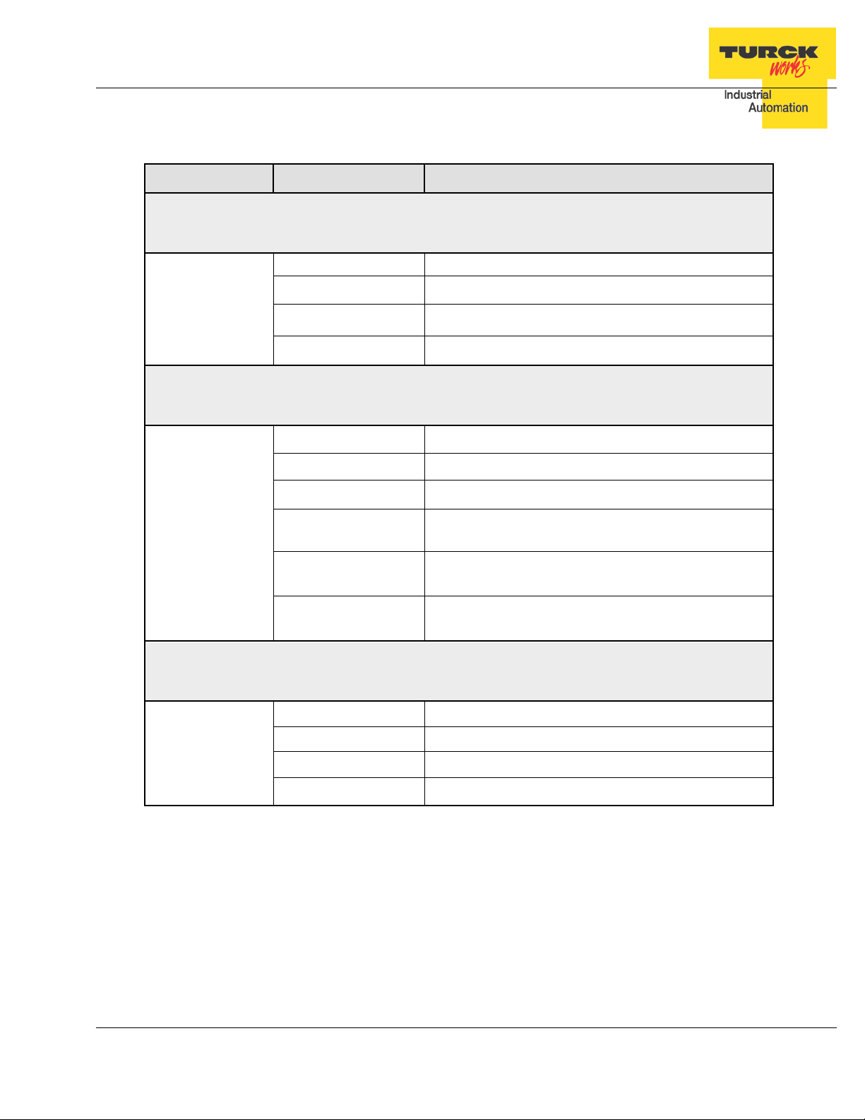
TBEN-LG Configuration Parameters
Item
name
TBEN Digital Inputs
Pulse_stretching
Trigger to an internal TOF
timer, (available for input
IStx
channels only)
Input_Inversion Inv.Ix
TBEN Digital Outputs
Disable_Auto_Recovery
Recovery mode of the out-
SROx
puts in case of short circuit
Description
It is an input signal OFF timer. The time base is
10ms. For example a value of 14 means 140ms.
Pulse stretch range [0-127].
Default = 0 value [Pulse stretching is disabled].
vated input (green LED on) is transmitted as a
logical 1 in the process data.
A 1 means that an activated input (green LED
on) is transmitted as a logical 0 in the process
data.
The behaviour of an output that recovers from
short condition is controlled by this parameters:
= 0, automatic recovery is enabled; Output tu rns
ON after short condition
= 1, automatic recovery is disabled; Output stays
OFF after short condition.
Default = 0
Output_Enable Out Enable x
TURCK • 3000 Campus Drive • Minneapolis, MN 55441-2656 40
Phone: 763.553.7300 • Toll Free: 800.544.7769 • Fax: 763.553.0708 • www.turck.us
Only available on DXP devices.
0 = output driver is not be enabled.
1 = output driver is enabled
Default = 1
Page 41

TBEN-LG-8DIP-8DOP
Byte2
Byte8
Byte14
Byte20
ISt5
TBEN-LG EtherNet/IP
TM
Configuration Guide
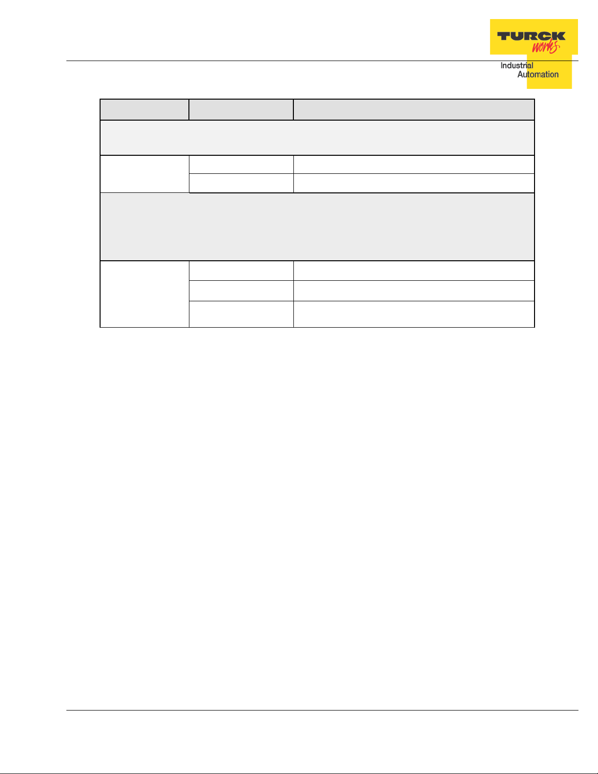
Configuration Assembly Data Structure
The structure of the configuration data is different for each TBEN-LG device, as follows:
Bit7 BIt6 Bit5 Bit4 Bit3 Bit2 Bit1 Bit0
Byte0
Byte1
Byte3
Byte4
Byte5
Byte6
Byte7
Byte9 Reserved QC
Byte10 Inv I7 Inv I6 Inv I5 Inv I4 Inv I3 Inv I2 Inv I1 Inv I0
Byte11 SRO 7 SRO 6 SRO 5 SRO 4 SRO 3 SRO 2 SRO 1 SRO 0
Byte12
Reserved
Reserved Byte13
Byte15 ISt0
Byte16 ISt1
Byte17 ISt2
Byte18 ISt3
Byte19 ISt4
Byte21 ISt6
Byte22 ISt7
Byte 23-45 Reserved
Table 2.4 – TBEN-LG-8DIP-8DOP configuration data
Abbreviations:
• QC Quick Connect
• INVx Input Inversion
• SROx Output Short Recovery
• IStx Input pulse stretching
• OE O ut put enable
TURCK • 3000 Campus Drive • Minneapolis, MN 55441-2656 41
Phone: 763.553.7300 • Toll Free: 800.544.7769 • Fax: 763.553.0708 • www.turck.us
Page 42

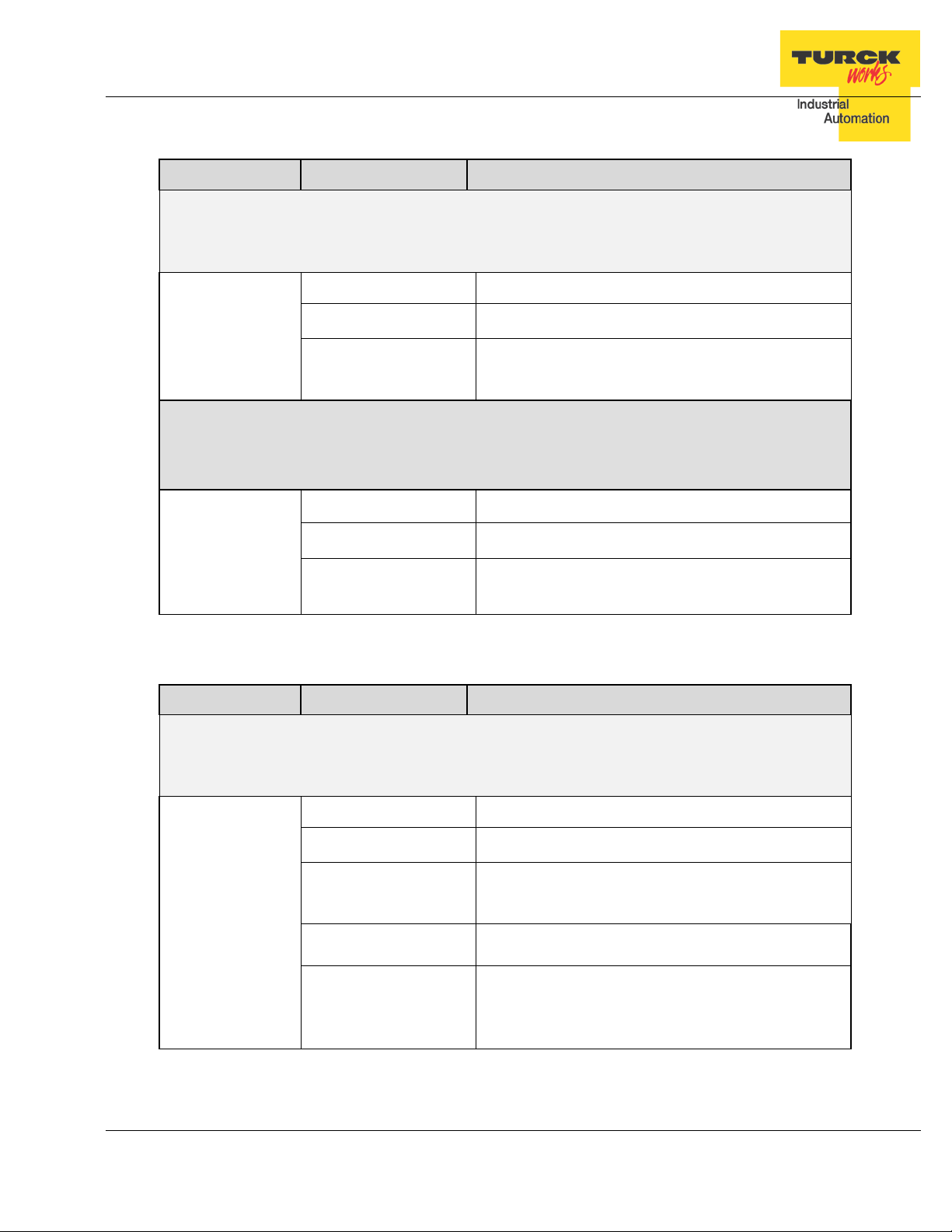
TBEN-LG-16DIP
Byte0
Byte2
Byte8
Byte12
Byte14
ISt1
Byte18
ISt3
Byte20
ISt7
ISt9
Byte26
ISt13
Byte30
TBEN-LG EtherNet/IP
TM
Configuration Guide
Byte1
Byte3
Byte4
Byte5
Byte6
Byte7
Byte9
Byte10
Byte11
Byte13
Byte15
Byte16
Byte17
Bit7 BIt6 Bit5 Bit4 Bit3 Bit2 Bit1 Bit0
Reserved
Reserved QC
Reserved
Inv I7 Inv I6 Inv I5 Inv I4 Inv I3 Inv I2 Inv I1 Inv I0
Inv I15 Inv I14 Inv I13 Inv I12 Inv I11 Inv I10 Inv I9 Inv I8
Reserved
ISt0
ISt2
Byte19
Byte21
Byte22
Byte23
Byte24
Byte25
Byte27
Byte28
Byte29
Byte 31-45
ISt4
ISt5
ISt6
ISt8
ISt10
ISt11
ISt12
ISt14
ISt15
Reserved
Table 2.5 – TBEN-LG-16DIP configuration data
TURCK • 3000 Campus Drive • Minneapolis, MN 55441-2656 42
Phone: 763.553.7300 • Toll Free: 800.544.7769 • Fax: 763.553.0708 • www.turck.us
Page 43

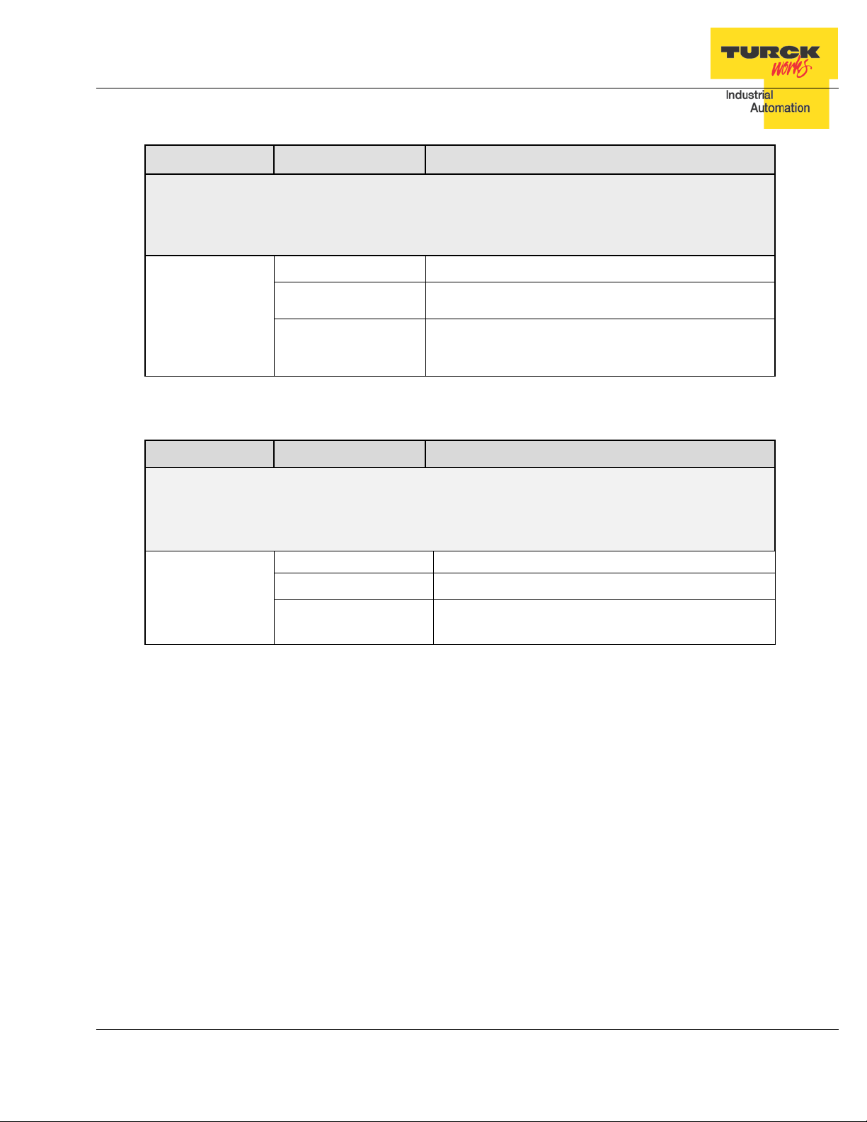
TBEN-LG-16DOP
Byte0
Byte4
Byte6
Byte10
SRO 7
SRO 6
SRO 5
SRO 4
SRO 3
SRO 2
SRO 1
SRO 0
TBEN-LG EtherNet/IP
TM
Configuration Guide
Byte1
Byte2
Byte3
Byte5
Byte7
Byte8
Byte9 Reserved QC
Byte11 SRO 15 SRO 14 SRO 13 SRO 12 SRO 11 SRO 10 SRO 9 SRO 8
Byte12
Byte13
Byte 14-45 Reserved
Bit7 BIt6 Bit5 Bit4 Bit3 Bit2 Bit1 Bit0
Reserved
Reserved
Table 2.6 – TBEN-LG-16DOP configuration data
TURCK • 3000 Campus Drive • Minneapolis, MN 55441-2656 43
Phone: 763.553.7300 • Toll Free: 800.544.7769 • Fax: 763.553.0708 • www.turck.us
Page 44

TBEN-LG-16DXP
Byte0
Byte4
Byte6
Byte10
Byte16
OE 7
OE 6
OE 5
OE 4
OE 3
OE 2
OE 1
OE 0
Byte18
Reserved
Byte22
ISt3
Byte24
ISt5
Byte28
ISt9
Byte34
ISt15
TBEN-LG EtherNet/IP
TM
Configuration Guide
Byte1
Byte2
Byte3
Byte5
Byte7
Byte8
Byte9 Reserved QC
Byte11
Byte12 Inv I7 Inv I6 Inv I5 Inv I4 Inv I3 Inv I2 Inv I1 Inv I0
Byte13 Inv I15 Inv I14 Inv I13 Inv I12 Inv I11 Inv I10 Inv I9 Inv I8
Byte14 SRO 7 SRO 6 SRO 5 SRO 4 SRO 3 SRO 2 SRO 1 SRO 0
Byte15 SRO 15 SRO 14 SRO 13 SRO 12 SRO 11 SRO 10 SRO 9 SRO 8
Byte17 OE 15 OE 14 OE 13 OE 12 OE 11 OE 10 OE 9 OE 8
Bit7 BIt6 Bit5 Bit4 Bit3 Bit2 Bit1 Bit0
Reserved
Reserved
Byte19 ISt0
Byte20 ISt1
Byte21 ISt2
Byte23 ISt4
Byte25 ISt6
Byte26 ISt7
Byte27 ISt8
Byte29 ISt10
Byte30 ISt11
Byte31 ISt12
Byte32 ISt13
Byte33 ISt14
Byte 35-45 Reserved
Table 2.7 – TBEN-LG-16DXP configuration data
TURCK • 3000 Campus Drive • Minneapolis, MN 55441-2656 44
Phone: 763.553.7300 • Toll Free: 800.544.7769 • Fax: 763.553.0708 • www.turck.us
Page 45

TBEN-LG EtherNet/IP
TM
Configuration Guide
TBEN-LG Profile Info
The device property is a subject to change. It provides path to view installed EDS file: right-click
on the device and select “Properties”:
Click on marked icon and follow instructions:
TURCK • 3000 Campus Drive • Minneapolis, MN 55441-2656 45
Phone: 763.553.7300 • Toll Free: 800.544.7769 • Fax: 763.553.0708 • www.turck.us
Page 46

TBEN-LG EtherNet/IP
TM
Configuration Guide
TBEN Configuration Using Generic Device
Earlier versions of RSlogix5000 Programming Software and Logix controllers, revision 19 or
less do not support EDS files. In such case, TBEN may be configured using Ethernet Generic
Module profile. The TBEN device configuration includes following steps:
− Create / open existing RSLogix5000 project
− Add Ethernet Generic device (as seen in RSLogix5000 rev 16)
− Add Ethernet Generic device (as seen in RSLogix5000 rev 20 and up)
− Configure device by entering assembly instances and data size as follows:
TURCK • 3000 Campus Drive • Minneapolis, MN 55441-2656 46
Phone: 763.553.7300 • Toll Free: 800.544.7769 • Fax: 763.553.0708 • www.turck.us
Page 47

TBEN-LG EtherNet/IP
TM
Configuration Guide
Configure TBEN-LG-16DIP
Note: “Comm Format” is always “Data – INT”.
Configure TBEN-LG-16DOP
TURCK • 3000 Campus Drive • Minneapolis, MN 55441-2656 47
Phone: 763.553.7300 • Toll Free: 800.544.7769 • Fax: 763.553.0708 • www.turck.us
Page 48

TBEN-LG EtherNet/IP
TM
Configuration Guide
Configure TBEN-LG-8DIP-8DOP
Configure TBEN-LG-16DXP
TURCK • 3000 Campus Drive • Minneapolis, MN 55441-2656 48
Phone: 763.553.7300 • Toll Free: 800.544.7769 • Fax: 763.553.0708 • www.turck.us
Page 49

TBEN-LG EtherNet/IP
TM
Configuration Guide
Configure Connection
The “Connection” page setup is identical for all TBEN devices as follows:
Controller organizer differentiates between EDS and Generic configured device by default icon.
TURCK • 3000 Campus Drive • Minneapolis, MN 55441-2656 49
Phone: 763.553.7300 • Toll Free: 800.544.7769 • Fax: 763.553.0708 • www.turck.us
Page 50

TBEN-LG EtherNet/IP
TM
Configuration Guide
TBEN Web Server
Open the web server by entering the device IP address in a web browser.
If IP address is not assigned to the device (DHCP, BootP server etc.), it’s the web server can
be opened using the default IP address 192.168.1.254.
Home Page
The home or start page of the web server shows general device information, network settings
and network status. There are several pages such as "Station Diagnostics", "Ethernet Statistics"
and "Links" which can be accessed for viewing.
TURCK • 3000 Campus Drive • Minneapolis, MN 55441-2656 50
Phone: 763.553.7300 • Toll Free: 800.544.7769 • Fax: 763.553.0708 • www.turck.us
Page 51

TBEN-LG EtherNet/IP
TM
Configuration Guide
Login / password
In order to get access to the extended functions of the web server and access to device setup,
login to the web server as administrator.
Enter initial password as “password” and click Login. The administrator privileges allow changing device setup using page links listed to the left. The home page shows the same information:
TURCK • 3000 Campus Drive • Minneapolis, MN 55441-2656 51
Phone: 763.553.7300 • Toll Free: 800.544.7769 • Fax: 763.553.0708 • www.turck.us
Page 52

TBEN-LG EtherNet/IP
TM
Configuration Guide
Network Configuration
The network configuration page is used to modify EtherNet port settings and device IP address.
TURCK • 3000 Campus Drive • Minneapolis, MN 55441-2656 52
Phone: 763.553.7300 • Toll Free: 800.544.7769 • Fax: 763.553.0708 • www.turck.us
Page 53

TBEN-LG EtherNet/IP
TM
Configuration Guide
Station Configuration
The station configuration page is used for enabling / disabling listed features. It is recommended
to keep default setup of the device.
Notes:
− Disabling GW Status and/or Control word shifts the position of the IO data map. Do not
change.
− “Submit” button applies changes to the device setup
− "Reset" only resets the changes done in the web server mask, back to the original values
− "Reboot" executes a power-cycle at the device.
− “Reset to Factory Defaults” corresponds to switch position 900 and it restores factory de-
fault setup, including password.
TURCK • 3000 Campus Drive • Minneapolis, MN 55441-2656 53
Phone: 763.553.7300 • Toll Free: 800.544.7769 • Fax: 763.553.0708 • www.turck.us
Page 54

TBEN-LG EtherNet/IP
TM
Configuration Guide
Station Diagnostics
The diagnostics page provides historical content of diagnostics from the last device power-up.
Ethernet Statistics
The Ethernet statict ics page provide currrent status and statistics of Ethernet ports.
TURCK • 3000 Campus Drive • Minneapolis, MN 55441-2656 54
Phone: 763.553.7300 • Toll Free: 800.544.7769 • Fax: 763.553.0708 • www.turck.us
Page 55

TBEN-LG EtherNet/IP
TM
Configuration Guide
IO Parameters
The IO parameters page is used to change setup of device IO behavior such as:
− Invert state of discrete input
− Disable automatic recovery of an output upon recovery from a short condition
− Pulse stretching value is in range 0-127; input signal is extended in steps of 10msec
from 0-1270 msec.
TURCK • 3000 Campus Drive • Minneapolis, MN 55441-2656 55
Phone: 763.553.7300 • Toll Free: 800.544.7769 • Fax: 763.553.0708 • www.turck.us
Page 56

TBEN-LG EtherNet/IP
TM
Configuration Guide
TURCK • 3000 Campus Drive • Minneapolis, MN 55441-2656 56
Phone: 763.553.7300 • Toll Free: 800.544.7769 • Fax: 763.553.0708 • www.turck.us
 Loading...