

Page 1

TBEN-LF
EtherNet/IP
TM
Configuration
Guide
0719A
Page 2

2
— This page intentionally left blank —
Page 3

3
1 General Information 4
1.1 About these instructions 4
1.2 Explanation of symbols used 4
1.2.1 Warnings 4
1.3 Contents 5
1.4 Feedback about these instructions 5
1.5 Technical support 5
2 Getting Started 6
2.1 About this document 6
2.2 Factory default IP address 6
2.3 Address switches 6
2.3.1 Static rotary mode 7
2.3.2 BOOTP mode (300) and DHCP mode (400) 7
2.3.3 PGM mode (500) 7
2.3.4 PGM-DHCP mode (600) 7
2.3.5 Factory Reset mode (900) 7
2.3.6 Restore IP Address (000) 8
2.4 TURCK Service Tool (TST) 8
2.4.1 Search (F5) 9
2.4.2 DHCP Server (F6) 9
3 TBEN-LF Quick View 12
3.1 Installation instruction and pinout 12
3.1.1 Dimensions and connector assignment 12
3.1.2 Ethernet P1 and P2 connectors pin assignment 12
3.1.3 Discrete IO connector pin assignment 13
3.1.4 Power connector pin assignment and distribution 14
3.1.5 LEDs 15
3.2 IO data maps 17
3.3 Generic device configuration 19
3.3.1 TBEN-LF-16DIP 20
3.3.2 TBEN-LF-16DOP 20
3.3.3 TBEN-LF-16DXP 21
3.3.4 TBEN-LF-8DIP-8DOP 21
4 EtherNet/IP Class Objects 22
4.1 EtherNet/IP Standard Objects 23
4.2 EtherNet/IP Vendor Specific Objects 27
Page 4
4
1 General Information
1.1 About these instructions
The following configuration guide describes the setup, functions, and use of the TBEN-LF stations. It helps you
to plan, design, and implement the system for its intended purpose.
Note*: Please read this manual carefully before using the system. This will prevent the risk of personal injury
or damage to property or equipment. Keep this manual safe during the service life of the system. If the system
is passed on, be sure to transfer this manual to the new owner as well.
1.2 Explanation of symbols used
1.2.1 Warnings
Action-related warnings are placed next to potentially dangerous work steps and are marked by graphic
symbols. Each warning is initiated by a warning sign and a signal word that expresses the gravity of the
danger. The warnings have absolutely to be observed:
DANGER!
DANGER indicates an immediately dangerous situation, with high risk, the death or severe injury, if
not avoided.
WARNING!
WARNING indicates a potentially dangerous situation with medium risk, the death or severe injury, if
not avoided.
ATTENTION!
ATTENTION indicates a situation that may lead to property damage, if it is not avoid-ed.
NOTE
In NOTES you find tips, recommendations and important information. The notes facilitate work,
provide more information on specific actions and help to avoid overtime by not following the correct
procedure.
➢ CALL TO ACTION
This symbol identifies steps that the user has to perform.
➔ RESULTS OF ACTION
This symbol identifies relevant results of steps
Italic Text in Italic is associated with the function of the third party software or application
(E.g. Controller Organizer)
Page 5

5
1.3 Contents
The TBEN-LF EtherNet/IP configuration guide provides information about configuration of the following
modules:
◼ TBEN-LF-16DIP
◼ TBEN-LF-16DOP
◼ TBEN-LF-8DIP-8DOP
◼ TBEN-LF-16DXP
The “TBEN-LF”, assigned to the product family, is used throughout the guidet to describe the common
features of the devices.
The complementary documentation and files:
◼ TBEN-LF data sheets
◼ EDS files revision 2.7
The Rockwell PLC demo:
◼ 1756-L72 controller v30
◼ 1756-EN2TR Ethernet Bridge
◼ Studio5000 Logic Designer V30
1.4 Feedback about these instructions
We make every effort to ensure that these instructions are as informative and as clear as possible. If you have
any suggestions for improving the design or if some information is missing in the document, please send your
suggestions to techdoc@turck.com.
1.5 Technical support
For additional support, email inquiries to appsupport@turck.com, or call Application Support at 763-553-7300,
Monday-Friday 8AM-5PM CST.
Page 6
6
2 Getting Started
2.1 About this document
The configuration guide provides information about configuration of the TBEN-LF including:
◼ Address switches
◼ IP address assignment
◼ Configuration options with Rockwell and Omron PLCs
NOTE
The device data sheet and technical information is available for download at
www.turck.us
2.2 Factory default IP address
The TBEN-LF default rotary switches are set at 000 with default IP address of:
◼ IP address: 136.129.1.1
◼ Netmask: 255.255.0.0
NOTE
Position 000 is used to “Restore” or recover the default IP address if lost or forgotten.
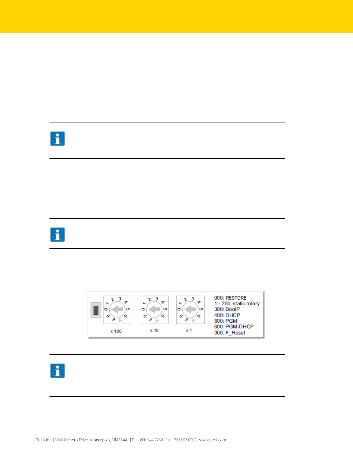
2.3 Address switches
The device has 3 rotary address switches (see Figure 2.2 below). The position of the them determines the
mode of operation.
Figure 2.1 – Rotary switches
NOTE
Protective cover opened - Protection class IP65/IP67/IP69K not warranted
➢ Screw the protective cover over the rotary coding-switches firmly
➢ Check if seal of the protective cover is correctly placed
Page 7

7
Table 2.1 below provides a description of the device action when switches are set to a specific position and
the device is powered up.
Switch position
Mode
Description
000
Restore
IP address is restored to 136.129.1.1
001,…,254
Static rotary
mode
Sets the last octet of IP address in range [1…254].
300
BOOTP
BOOTP client is active and requesting an IP address
400
DHCP
DHCP client is active and requesting an IP address
500
PGM
Device comes up with the last IP address saved in
EEPROM. IP address is programmable.
600
PGM-DHCP
DHCP client is active and requesting an IP address.
When IP address is acquired, the device transitions to
PGM mode.
900
Factory Reset
Device is reset to the factory default setup.
Table 2.2: Address Modes
2.3.1 Static rotary mode
Set the last octet of the IP address using the rotary switches in the range [xxx = 1,…, 254],
e.g. 136.129.1.120 or 10.10.10.120.
2.3.2 BOOTP mode (300) and DHCP mode (400)
When rotary switches are set to either 300 or 400, the device BOOTP or DHCP client is active, requesting an
IP address assignment. The setup procedure - from any switch position:
➢ Turn OFF device power and set switches to 300 or 400
➢ Turn ON device power
➢ Start BOOTP / DHCP server and assign IP address
➢ Wait for the acknowledgement from the server
➢ Set rotary switches to either the last octet of the IP address or to 500 (PGM)
➢ Cycle the power.
2.3.3 PGM mode (500)
When rotary switches are set to 500 while device is powered, the current IP address, Netmask and Gateway
addresses are saved into the EEPROM. The IP address is programmable and may be changes using TURCK
Service Tool. The setup procedure – from any switch position set switches to 500 and then cycle the power.
2.3.4 PGM-DHCP mode (600)
When out-of-box TBEN-LF is powered for the first time, while the rotary switches are set to 600, the device
DHCP client is enabled and running. Use any DHCP server to assign the IP address. When IP address is
acquired, the DHCP client is disabled and device transitions to the PGM mode.
2.3.5 Factory Reset mode (900)
When rotary switches are set to 900 and the power is cycled, the device resets itself to the factory default
mode (out-of-box). The QC setup is deleted; the ETH1 and ETH2 ports are set to Autonegotiation and AutoMDIX.
Page 8

8
From any switch position:
➢ Set address switches to 900
➢ Cycle the power of the device and wait 10sec
➢ Set switches to either static address 1…254 or specific mode of operation 300/400/500/600
➢ Cycle the power.
2.3.6 Restore IP Address (000)
When rotary switches are set to 000 and the power is cycled, the IP address is set to 136.129.1.1. The device
preserves custom data /setup while restoring IP address.
From any switch position:
➢ Set the address switches to 000
➢ Cycle the power of the device and wait 10sec
➢ Set switches to either static position or 300/400/500/600 mode
➢ Cycle the power.
2.4 TURCK Service Tool (TST)
The TURCK Service Tool can be downloaded from the TURCK Web site:
➢ Enter “TURCK Service Tool” in the search field
➢ Follow the link
➢ Download and install the tool
➢ The tool is used for the management of the TURCK devices only
Figure 2.3 – TURCK Web page
The tool has a set of action buttons in the tool bar:
Figure 2.4 – Service Tool
Page 9
9
The tool features are:
◼ It scans for existing devices (F5). All devices are found by using DCP (PROFINET Standard) and
IBTP (TURCK Service Protocol) protocols. The IBTP protocol provides extended information such
as FW version and operating mode improved scanning are read out of TURCK devices and
displayed.
◼ It set an IP address (F2)
◼ It locates device using Wink function (F3)
◼ Actions menu that resets the device to the factory default or reset network (F4)
◼ It assigns the PROFINET name to the device
◼ It supports Clipboard menu
◼ Expert view, when enabled, provides additional functions like DHCP Server, ARGEE and BEEP
features by TURCK multiprotocol device
◼ DHCP server
◼ ARGEE status
◼ BEEP status
Frequently used action buttons / functions are:
◼ Search (F5)
◼ Change (F2)
◼ DHCP (F6)
◼ Action (F4)
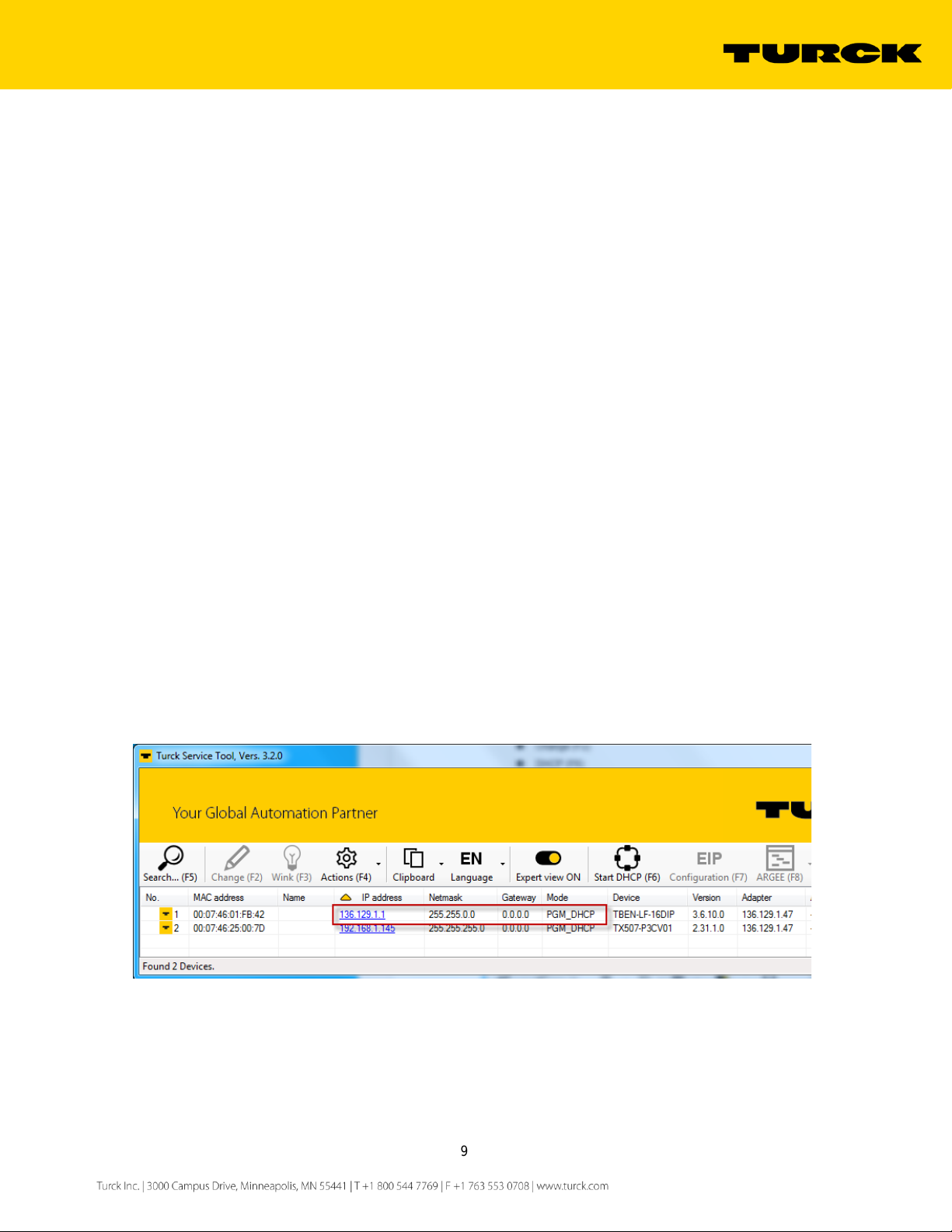
2.4.1 Search (F5)
The Search is used to identify TURCK multiprotocol device on the continuous physical network segment,
including devices connected to the layer 2 switches. The IP address 136.129.1.1 appears when the device is
in the PGM-DHCP mode and DHCP client is active. The IP address transitions to 0.0.0.0 when DCHP server
is started.
Figure 2.5 – Search function
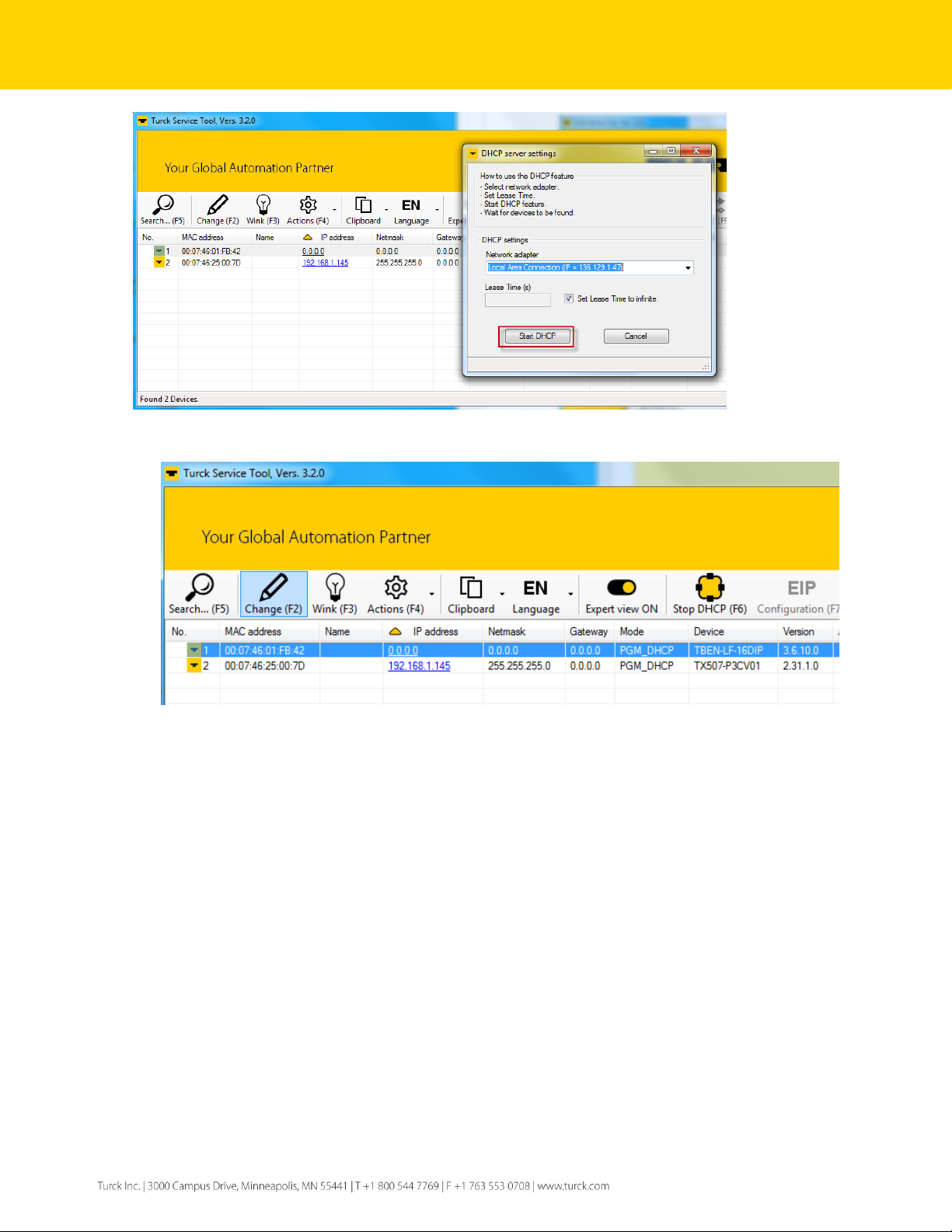
2.4.2 DHCP Server (F6)
The IP address may be assigned to the device using DHCP server (F6). Procedure:
➢ Search (F5) to discover device with address 136.129.1.1
➢ Start DHCP server (F6)
➢ Select network adapter in the DHCP server settings page and click Start DHCP
Page 10
10
Figure 2.6 – Initialize DHCP server
➢ Highlight the device with 0.0.0.0 IP address
Figure 2.7 – Device DHCP client active view
➢ Click Change (F2); A “Change device configuration” pop-up page appears
➢ Assign IP address and click at Set in device button
Page 11

11
Figure 2.8 – Set IP Configuration
➢ Click at Stop DHCP (F6) button
Figure 2.9 – Stop DHCP server
Page 12

12
3 TBEN-LF Quick View
3.1 Installation instruction and pinout
The summary of the device installation guidance, connector’s assignment, power distribution and grounding
requirements are as follows.
3.1.1 Dimensions and connector assignment
Figure 3.1 – Connector assignment
3.1.2 Ethernet P1 and P2 connectors pin assignment
Figure 3.2 – P1 and P2 connector pinout
Page 13

13
3.1.3 Discrete IO connector pin assignment
➢ Discrete inputs
Connect digital sensors to the device according to the pin assignment.
Figure 3.3 – Discrete input wiring diagram
➢ Discrete outputs
Connect digital actuators to the device according to the pin assignment.
Figure 3.4 – Discrete output wiring diagram
Page 14

14
➢ Discrete combined IO
Connect digital combined IO to the device according to the pin assignment
Figure 3.5 – Discrete combined IO wiring diagram
3.1.4 Power connector pin assignment and distribution
➢ Connect power to the device according to the pin assignment
Figure 3.6 – X1 and X2 connector pinout
Figure 3.7 – V1 and V2 power distribution
Page 15

15
3.1.5 LEDs
Figure 3.8 – LED assignment
LED
Color
Status
Meaning
Remedy
PWR
green
off
V1 missing or < 18 VDC
Check V1
on
V1 and V2 OK
blinking
V2 missing or < 18 VDC
Check V2
ETHx
green
on
Link established, 100Mbps
blinking
Ethernet traffic, 100Mbps
yellow
on
Link established, 10Mbps
blinking
Ethernet traffic, 10Mbps
none
off
No Ethernet link
Check Ethernet connection
ERR
green
on
No diagnostic message
red
on
Diagnostic message pending
BUS
green
on
Active connection to a master
blinking
Device is ready for operation
red
on
IP address conflict
Check duplicate IP address
Restore mode (900)
Check setup of rotary switches
Connection timeout
Check media
blinking
Blink / wink command active
red/green
on
Autonegotiation
BootP/DHCP client active
Waiting for IP address assignment
Figure 3.9 – Module LED behavior
Page 16

16
TBEN-LF-16DIP LED Status I/O
LED
Color
Status
Meaning
Remedy
LED 0…15
green
on
Input active
off
Input off
red blinking
Overcurrent at input
Check short condition
TBEN-LF-16DOP LED Status I/O
LED
Color
Status
Meaning
Remedy
LED 0…15
green
on
Output active
off
Output off
red blinking
Overcurrent at output
Check short condition
TBEN-LF-16DXP LED Status I/O
LED
Color
Status
Meaning
Remedy
LED 0…15
green
on
IO signal active
input or output
off
IO signal off
input or output
red
blinking
Overcurrent at input
Check input short condition
Solid
Overcurrent at output
Check output short condition
TBEN-LF-8DIP-8DOP LED Status I/O
LED
Color
Status
Meaning
Remedy
LED 0…7
green
on
Input active
off
Input off
red blinking
Overcurrent at input
Check short condition
LED 8…15
green
on
Output active
off
Output off red
Overcurrent at output
Check short condition
Figure 3.10 – IO LED behavior
Page 17

17
3.2 IO data maps
◼ TBEN-LF-16DIP
◼ TBEN-LF-16DOP
◼ TBEN-LF-8DIP-8DOP
◼ TBEN-LF-16DXP
Page 18

18
IO Map key:
Device status word
Meaning
DIAG
Module Diagnostics Available
V2
Undervoltage Field Supply V2 <18V
V1
Undervoltage Field Supply V1 <18V
COM
Modulebus Communication Lost
CFG
Modulebus Configuration Error
ETH1
Ethernet Port 1 Errors
ETH2
Ethernet Port 2 Errors
FCE
Force Mode Enabled
Device scheduled diagnostics
EM0
Internal slot 0
EC5
Diagnostics active
Error-Cx
Input short at connector Cx [x=0, 1, …, 7]
OSC-x
Output short at condition at output x [x=0, 1, …, 15]
Device IO channels
I-x
Input channel [x=0, 1, …, 15]
O-x
Output channel [x=0, 1, …, 15]
◼ TBEN-LG Configuration assembly data and size
Configuration Assembly Data
Bit 7
Bit 6
Bit 5
Bit 4
Bit 3
Bit 2
Bit 1
Bit 0
Byte 0
reserved
Byte 1
reserved
Byte 2
reserved
Byte 3
reserved
Byte 4
reserved
Byte 5
reserved
Byte 6
reserved
Byte 7
reserved
Byte 8
reserved
Byte 9
reserved
QC
Byte 10
reserved
Byte 11
reserved
Byte 12
reserved
Byte 13
reserved
Byte 14
reserved
Byte 15
reserved
QC = QC enable / disable bit
Page 19

19
3.3 Generic device configuration
The TBEN-LF is configured with the Rockwell PLCs using “ETHERNET MODULE – Generic Ethernet Module”
profile:
TBEN-LF configuration requirements:
◼ Catalog Number: Generic Ethernet Module
◼ Comm.Format: Data – INT
◼ Select “Connection Parameters” listed for specific device as follows:
Figure 11: TBEN-LF connection summary
Figure 12: New Module page
Page 20

20
3.3.1 TBEN-LF-16DIP
Figure 13: TBEN-LF-16DIP configuration page
3.3.2 TBEN-LF-16DOP
Figure 14: TBEN-LF-16DOP configuration page
Page 21

21
3.3.3 TBEN-LF-16DXP
Figure 15: TBEN-LF-16DXP configuration page
3.3.4 TBEN-LF-8DIP-8DOP
Figure 16: TBEN-LF-8DIP-8DOP general page
Page 22

22
4 EtherNet/IP Class Objects
The TBEN-LF supports following CIP1 objects:
CIP Object Classes
Class Code
Object type
01 (0x01)
Identity Object
04 (0x04)
Assembly Object
06 (0x06)
Connection Manager
71 (0x47)
DLR Object
72 (0x48)
QoS Object
245 (0xF5)
TCP/IP Interface Object
246 (0xF6)
Ethernet Link Object
Figure 4.1 – EtherNet/IP standard objects
The Vendor Specific objects are defined hereafter:
Following
VSC Object Classes
Class Code
Object type
100 (0x64)
Gateway Object
117 (0x75)
DXP Object
Figure 4.2 – Vendor Specific objects
Common service:
Common class and instance services
Service code
Service Name
01 (0x01)
Get_Attribute_All
05 (0x05)
Reset
14 (0x0E)
Get_Attribute_Single
16 (0x10)
Set_Attribute_Single
Figure 4.3 – Common services
1
The CIP Networks Library, Volume 1, Common Industrial, Protocol (CIP
TM
) by ODVA, Edition 3.24, April 2018
The CIP Networks Library, Volume 2, EtherNet/IP Adaptation of CIP, by ODVA, Edition 1.23, April 2018
Page 23

23
4.1 EtherNet/IP Standard Objects
Identity Object
Class code: 01 (0x01)
Instance 1 (0x01) Attributes
Attribute
Access
Name
Data type
Value
1 (01h)
Get
Vendor
UINT
48 (0x0030)
2 (02h)
Get
Product Type
UINT
12 (0x000C)
3 (03h)
Get
Product Code
UINT
Device specific code
4 (04h)
Get
Revision major
USINT
2
Revision minor
USINT
7
Revision Internal
35
5 (05h)
Get
Device Status
WORD
Status
6 (06h)
Get
Serial Number
UDINT
Device specific number
7 (07h)
Get
Product name
STRING[length]
TBEN-LF-xxxx
Supported services
Service code
Class
Instance
Service
01 (0x01)
yes
Get_Attribute_All
05 (0x05)
yes
Reset
14 (0x0E)
yes
Get_Attribute_Single
Figure 4.5 – Identity Object
Assembly Object
Class code: 04 (0x04)
Instance 103 (0x67) Attributes
Attribute
Access
Name
Data type
Value
3 (03h)
Get
Input data
ARRAY of BYTE
4 (04h)
Get
Size
UINT
Number of bytes in Attr 3
Instance 104 (0x68) Attributes
Attribute
Access
Name
Data type
Value
3 (03h)
Get
Output data
ARRAY of BYTE
4 (04h)
Get
Size
UINT
Number of bytes in Attr 3
Supported services
Service code
Class
Instance
Service
14 (0x0E)
yes
Get_Attribute_Single
Figure 4.6 – Assembly Object
NOTE
Refer to the following reference for the omitted attribute values:
The CIP Networks Library, Volume 1, Common Industrial, Protocol by ODVA, Edition 3.24, April 2018
The CIP Networks Library, Volume 2, EtherNet/IP Adaptation of CIP, by ODVA, Edition 1.23, April 2018
Page 24

24
Connection Manager
Class code: 06 (0x06)
Attribute
Access
Name
Data type
Value
Supported services
Service code
Class
Instance
Service name
84 (0x54)
yes
FWD_OPEN_CMD
78 (0x4E)
yes
FWD_CLOSE_CMD
Figure 4.7 – Connection Manager Object
DLR Object
Class code: 71 (0x47)
Class attributes
Attribute
Access
Name
Data type
Value
1 (0x01)
Get
Revision
UINT
3
Instance 1 attributes
Attribute
Access
Name
Data type
Value
1 (0x01)
Get
Network topology
USINT
2 (0x02)
Get
Network status
USINT
10 (0x0A)
Get
Active supervisor address
STRUCT.
12 (0x0C)
Get
Capability flags
DWORD
Supported services
Service code
Class
Instance
Service
14 (0x0E)
yes
yes
Get_Attribute_Single
Figure 4.8 – DLR Object
QoS Object
Class code: 72 (0x48)
Instance 1 attributes
Attribute
Access
Name
Data type
Value
4 (0x04)
Set
DSCP Urgent
USINT
5 (0x05)
Set
DSCP Scheduled
USINT
6 (0x06)
Set
DSCP High
USINT
7 (0x07)
Set
DSCP Low
USINT
8 (0x08)
Set
DSCP Explicit
USINT
Supported services
Service code
Class
Instance
Service
14 (0x0E)
yes
Get_Attribute_Single
16 (0x10)
yes
Set_Attribute_Single
Figure 4.9 – QoS Object
Page 25

25
TCP/IP Object
Class code: 245 (0xF5)
Class attributes
Attribute
Access
Name
Data type
Value
1 (01h)
Get
Revision
UINT
3
2 (02h)
Get
Max instance
UINT
1
3 (03h)
Get
No. of instances
UINT
1
Instance 1 attributes
Attribute
Access
Name
Data type
Value
1 (0x01)
Get
Status
DWORD
2 (0x02)
Get
Configuration capability
DWORD
3 (0x03)
Get
Configuration control
DWORD
4 (0x04)
Get
Physical Link
Structure of:
Path Size
UINT
Path
Padded EPATH
5 (0x05)
Get
Interface Configuration
Structure of:
Get
IP address
UDINT
Get
Network mask
UDINT
Get
Gateway address
UDINT
Get
Name server
UDINT
Get
Name server 2
UDINT
Get
Domain name
UDINT
6 (0x06)
Get
Host name
String
10 (0x0A)
Set
ACD Enable
Bool 11 (0x0B)
Get/Set
Last Conflict detect
Structure of:
12 (0x0C)
Get/Set
QuickConnet
Bool
Supported services
Service code
Class
Instance
Service
01 (0x01)
yes
Get_Attribute_All
14 (0x0E)
yes
yes
Get_Attribute_Single
16 (0x10)
yes
Set_Attribute_Single
Figure 4.10 – TCP/IP Object
Page 26

26
Ethernet Link Object
Class code: 246 (0xF6)
Class attributes
Attribute
Access
Name
Data type
Value
1 (0x01)
Get
Revision
UINT
3
2 (0x02)
Get
Max instance
UINT
3
3 (0x03)
Get
No. of instances
UINT
3
Instance 1, 2, 3, attributes
Attribute
Access
Name
Data type
Value
1 (0x01)
Get
Interface speed
UDINT
2 (0x02)
Get
Interface flags
DWORD
3 (0x03)
Get
Physical address
Array of USINT
4 (0x04)
Get
Interface counters
Structure of UDINT:
5 (0x05)
Get
Media counters
Structure of UDINT:
6 (0x06)
Set
Interface control
Structure of:
Control bits
WORD
Forced intf. Speed
UINT
7 (0x07)
Get
Interface type
USINT
10 (0x0A)
Set
Interface label
SHORT_STRING
14 (0x0D)
Get
Ethernet errors
UDINT
15 (0x0F)
Get
Link down counters
UDINT
Supported services
Service code
Class
Instance
Service
01 (0x01)
yes
Get_Attribute_All
14 (0x0E)
yes
yes
Get_Attribute_Single
16 (0x10)
yes
Set_Attribute_Single
76 (0x4C)
yes (attr. 4, 5)
Get_and_Clear
Figure 4.11 – Ethernet Link Object
Page 27

27
4.2 EtherNet/IP Vendor Specific Objects
Gateway Object
Class code: 100 (0x64)
Instance 2 attributes
Attribute
Access
Name
Data type
Value
109 (0x6D)
Get
GW Status Word
WORD
Structure of:
115 (0x73)
Get/Set
On Connection timeout
USINT
0: Switch IO Faulted
1: Switch IO OFF
2: Switch IO Hold
138 (0x8A)
Get/Set
Enable GW Status word
DWORD
0 = no; 1=yes
139 (0x8B)
Get/Set
Enable GW Control word
DWORD
0 = no; 1=yes
Supported services
Service ode
Class
Instance
Service
14 (0x0E)
yes
Get_Attribute_Single
16 (0x10)
yes
Set_Attribute_Single
Figure 4.20 – Gateway Object
DXP Object
Class code: 117 (0x75)
Instance 1 attributes
Attribute
Access
Name
Data type
Value
113 (71h)
Get
Digital In/Out – Input value
DWORD
0 - "Channel 0",
1 - "Channel 1",
2 - "Channel 2",
3 - "Channel 3",
4 - "Channel 4",
5 - "Channel 5",
6 - "Channel 6",
7 - "Channel 7",
8 - "Channel 8",
9 - "Channel 9",
10 - "Channel 10",
11 - "Channel 11",
12 - "Channel 12",
13 - "Channel 13",
14 - "Channel 14",
15 - "Channel 15",
16-31 – reserved,
115 (73h)
Get
Digital In/Out – Output value
DWORD
0 - "Channel 0",
1 - "Channel 1",
2 - "Channel 2",
3 - "Channel 3",
4 - "Channel 4",
5 - "Channel 5",
6 - "Channel 6",
7 - "Channel 7",
8 - "Channel 8",
9 - "Channel 9",
10 - "Channel 10",
11 - "Channel 11",
12 - "Channel 12",
13 - "Channel 13",
14 - "Channel 14",
15 - "Channel 15",
16-31 – reserved,
Page 28

28
119 (77h)
Get
Digital In/Out – Output
overcurrent
DWORD
0 - "Channel 0",
1 - "Channel 1",
2 - "Channel 2",
3 - "Channel 3",
4 - "Channel 4",
5 - "Channel 5",
6 - "Channel 6",
7 - "Channel 7",
8 - "Channel 8",
9 - "Channel 9",
10 - "Channel 10",
11 - "Channel 11",
12 - "Channel 12",
13 - "Channel 13",
14 - "Channel 14",
15 - "Channel 15",
16-31 – reserved,
121 (79h)
Get
Digital In/Out – Input overcurrent
VAUX
DWORD
0 - "Channel 0",
1 - "Channel 1",
2 - "Channel 2",
3 - "Channel 3",
4 - "Channel 4",
5 - "Channel 5",
6 - "Channel 6",
7 - "Channel 7",
8-31 – reserved,
127 (7Fh)
Get / Set
Digital In/Out – Invert digital
input
UDINT
0 - "Channel 0",
1 - "Channel 1",
2 - "Channel 2",
3 - "Channel 3",
4 - "Channel 4",
5 - "Channel 5",
6 - "Channel 6",
7 - "Channel 7",
8 - "Channel 8",
9 - "Channel 9",
10 - "Channel 10",
11 - "Channel 11",
12 - "Channel 12",
13 - "Channel 13",
14 - "Channel 14",
15 - "Channel 15",
16-31 – reserved,
137 (89h)
Get / Set
Digital In/Out – Manual reset
output after overcurrent
DWORD
0 - "Channel 0",
1 - "Channel 1",
2 - "Channel 2",
3 - "Channel 3",
4 - "Channel 4",
5 - "Channel 5",
6 - "Channel 6",
7 - "Channel 7",
8 - "Channel 8",
9 - "Channel 9",
10 - "Channel 10",
11 - "Channel 11",
12 - "Channel 12",
13 - "Channel 13",
14 - "Channel 14",
15 - "Channel 15",
16-31 – reserved,
139 (8Bh)
Get / Set
Digital In/Out – Activate output
DWORD
0 - "Channel 0",
1 - "Channel 1",
2 - "Channel 2",
3 - "Channel 3",
4 - "Channel 4",
5 - "Channel 5",
6 - "Channel 6",
7 - "Channel 7",
8 - "Channel 8",
9 - "Channel 9",
10 - "Channel 10",
Page 29

29
11 - "Channel 11",
12 - "Channel 12",
13 - "Channel 13",
14 - "Channel 14",
15 - "Channel 15",
16-31 – reserved,
149 (95h)
Get / Set
Digital In/Out 0 – Pulse stretch
USINT
0-255
150 (96h)
Get / Set
Digital In/Out 1 – Pulse stretch
USINT
0-255
151 (97h)
Get / Set
Digital In/Out 2 – Pulse stretch
USINT
0-255
152 (98h)
Get / Set
Digital In/Out 3 – Pulse stretch
USINT
0-255
153 (99h)
Get / Set
Digital In/Out 4 – Pulse stretch
USINT
0-255
154 (9Ah)
Get / Set
Digital In/Out 5 – Pulse stretch
USINT
0-255
155 (9Bh)
Get / Set
Digital In/Out 6 – Pulse stretch
USINT
0-255
156 (9Ch)
Get / Set
Digital In/Out 7 – Pulse stretch
USINT
0-255
157 (9Dh)
Get / Set
Digital In/Out 8 – Pulse stretch
USINT
0-255
158 (9Eh)
Get / Set
Digital In/Out 9 – Pulse stretch
USINT
0-255
159 (9Fh)
Get / Set
Digital In/Out 10 – Pulse stretch
USINT
0-255
160 (A0h)
Get / Set
Digital In/Out 11 – Pulse stretch
USINT
0-255
161 (A1h)
Get / Set
Digital In/Out 12 – Pulse stretch
USINT
0-255
162 (A2h)
Get / Set
Digital In/Out 13 – Pulse stretch
USINT
0-255
163 (A3h)
Get / Set
Digital In/Out 14 – Pulse stretch
USINT
0-255
164 (A4h)
Get / Set
Digital In/Out 15 – Pulse stretch
USINT
0-255
Supported services
Service code
Class
Instance
Service
14 (0x0E)
yes
Get_Attribute_Single
16 (0x10)
yes
Set_Attribute_Single
Figure 4.20 – DXP Object
Page 30

30
NOTE
Pulse stretch is a trigger to an internal TOF timer. The timer stretches an input discrete single
In 10msec increments. The time base is 10msec. Example:
0 = timer disabled (default value)
1 = 10 msec delay
10 = 100 msec delay
ATTENTION!
DXP object attributes cannot be SET while PLC – TBEN connection is running.
Page 31

31
TURCK sells its products through Authorized Distributors. These distributors provide our customers
with technical support, service and local stock. TURCK distributors are located nationwide –
Including all major metropolitan marketing areas
For Application Assistance or for the location of your nearest TURCK distributor, call:
1-800-544-7769
Specifications in this manual are subject to change without notice. TURCK also reserves the right to
make modifications and makes no guarantee of the accuracy of the information contained herein.
 Loading...