

turck TBEN-L5-4RFID-8DXP-CDS, TBEN-L4-4RFID-8DXP-CDS, TBEN-L4-4RFID-8DXP-CDS-WV, TBEN-L5-4RFID-8DXP-CDS-WV Instructions For Use Manual
Page 1

Your Global Automation Partner
Instructions for Use
TBEN-L…-4RFID-8DXPCDS…
Compact RFID Interface
Page 2

2
Hans Turck GmbH & Co. KG | T +49 208 4952-0 | F +49 208 4952-264 | more@turck.com | www.turck.com
Page 3

V02.00 | 2018/08
3
Contents
1 About these Instructions 7
1.1 Target groups 7
1.2 Explanation of symbols used 7
1.3 Other documents 7
1.4 Feedback about these instructions 7
2 Notes on the Product 8
2.1 Product identification 8
2.2 Scope of delivery 8
2.3 Legal requirements 8
2.4 Manufacturer and Service 8
3 For Your Safety 9
3.1 Intended use 9
3.2 General safety notes 9
4 Product Description 10
4.1 Device overview 10
4.1.1 Indication elements 10
4.1.2 Operating elements 10
4.2 Properties and features 11
4.3 Operating principle 11
4.4 Functions and operating modes 12
4.4.1 Multiprotocol function 12
4.4.2 Data transfer to the PLC 12
4.4.3 RFID channels – Operating modes 13
4.4.4 RFID commands 15
4.4.5 Loop counter function 15
4.4.6 Configurable digital channels – Functions 16
4.4.7 USB host port 16
4.4.8 USB device port 16
4.4.9 Compatible CODESYS versions 16
4.5 Technical Accessories 16
5 Mounting 17
5.1 Grounding the device 18
5.1.1 Grounding and shielding concept 18
5.1.2 Grounding the device (FG) 19
6 Connection 20
6.1 Connecting modules to Ethernet 20
6.2 Connecting the power supply 21
6.3 Connecting RFID read/write heads 22
6.4 Connecting digital sensors and actuators 23
7 Commissioning 24
7.1 Setting the IP address 24
7.1.1 Setting the IP address via switches on the device 24
7.1.2 Setting the IP address via the Turck Service Tool 26
7.1.3 Setting the IP address via the web server 28
7.2 Connecting the device to a Modbus master 29
Page 4

Contents
4
Hans Turck GmbH & Co. KG | T +49 208 4952-0 | F +49 208 4952-264 | more@turck.com | www.turck.com
7.2.1 Connecting the device with the controller 30
7.2.2 Renaming a Modbus slave 34
7.2.3 Setting up network interfaces 35
7.2.4 Setting Modbus channels (registers) 37
7.2.5 Setting the I/O mapping 39
7.2.6 Writing the application to the device 45
7.2.7 Connecting the device online with the controller 51
7.2.8 Reading out process data 51
7.3 Connecting a device to an EtherNet/IP™ controller 52
7.3.1 Configuring the device in CODESYS as an EtherNet/IP™ slave 53
7.3.2 Setting up the network interface 61
7.3.3 Installing an EDS file 65
7.3.4 Connecting the device with the controller 69
7.3.5 Reading out process data 72
7.4 Connecting a device to a Siemens controller 73
7.4.1 Configuring the device in CODESYS as a PROFINET device 74
7.4.2 Setting up the network interface 82
7.4.3 Connecting a device to a Siemens controller in the TIA Portal 86
7.4.4 Reading out process data 92
7.5 Starting the device as the Modbus master 93
7.5.1 Setting up the network interface 99
7.5.2 Setting Modbus channels (registers) 103
7.5.3 Reading out process data 105
8 Setting 106
8.1 RFID channels – Setting parameter data 108
8.1.1 Meaning of the parameter bits 109
8.1.2 HF applications – Selecting the tag type 111
8.1.3 HF applications – Setting the bridging time 113
8.1.4 HF applications – Setting Continuous mode 114
8.1.5 HF applications – Setting HF bus mode 115
8.1.6 UHF applications – Setting Continuous presence sensing mode 120
8.1.7 UHF applications – Transferring read/write head settings 120
8.2 RFID channels – Evaluating process input data 121
8.2.1 Meaning of the status bits 124
8.2.2 Using “Tag in detection range” bit (TP) or "pre-loading" the command 125
8.3 RFID channels – Writing process output data 126
8.3.1 Meaning of the command bits 129
8.4 Digital channels – Setting parameter data 131
8.4.1 Meaning of the parameter bits 131
8.5 Digital channels – Evaluating process input data 132
8.5.1 Meaning of the status bits 132
8.6 Digital channels – Writing process output data 133
8.6.1 Meaning of the command bits 133
8.7 Digital channels – Setting switchable VAUX power supply 134
8.7.1 VAUX switchable power supply – Parameter data 134
8.7.2 VAUX switchable power supply – Output data 135
8.8 RFID channels – Overview of commands 136
8.8.1 Idle command 138
8.8.2 Inventory command 139
8.8.3 Read command 142
8.8.4 Write command 143
8.8.5 Write and verify command 145
Page 5

V02.00 | 2018/08
5
8.8.6 Continuous mode 147
8.8.7 “Get data from buffer” command (Continuous mode/“Continuous presence sensing
mode”) 149
8.8.8 “Continuous presence sensing mode” command (UHF) 152
8.8.9 “Stop continuous (presence sensing) mode” command 153
8.8.10 Read/write head identification command 154
8.8.11 Switch off HF read/ command 155
8.8.12 Tune read/write head command 156
8.8.13 “Get HF read/write head address” command 157
8.8.14 “Set HF read/write head address” command 158
8.8.15 Direct read/write head command 159
8.8.16 Set tag password command 164
8.8.17 Set read/write head password command 166
8.8.18 Reset read/write head password command 167
8.8.19 Set tag protection command 168
8.8.20 Get HF tag protection status command 170
8.8.21 Set perma lock command 172
8.8.22 Tag info command 174
8.8.23 Kill UHF tag 176
8.8.24 Restore settings UHF read/write head command 177
8.8.25 Backup settings UHF read/write head command 178
8.8.26 “Get UHF read/write head error/status” command 179
8.8.27 Reset command 182
8.9 Setting RFID interfaces via the web server 183
8.9.1 Opening a web server 183
8.9.2 Editing settings in the web server 184
8.10 Testing and parameterizing RFID interfaces via the DTM 190
8.10.1 Connecting the device with the PC 190
8.10.2 Editing parameter data with the DTM – Online parameterization 193
8.10.3 Reading process input data with the DTM – Measured value 194
8.10.4 Changing process output data with the DTM – Simulation 195
8.10.5 Evaluating diagnostics with the DTM 196
8.10.6 Example: Executing a read command with the DTM 197
8.11 Setting UHF read/write heads 199
8.12 Opening WebVisu 199
8.13 Using SFTP access 200
9 Operation 201
9.1 Executing a command and calling data 201
9.1.1 Typical times for command processing 201
9.2 Using fragmentation 203
9.3 Using commands with a loop counter function 203
9.4 Using NEXT mode 204
9.4.1 Example: Using NEXT mode for a read command 204
9.5 Using Inventory command and Continuous (presence sensing) mode 205
9.6 Executing commands in HF bus mode 205
9.7 LEDs 206
9.8 Software diagnostic messages 208
9.8.1 Diagnostic messages – Gateway functions 208
9.8.2 Diagnostic messages – RFID channels 208
9.8.3 Diagnostic messages – Digital channels 209
9.8.4 Diagnostic messages – Module status 209
9.9 Reading error codes 210
Page 6

Contents
6
Hans Turck GmbH & Co. KG | T +49 208 4952-0 | F +49 208 4952-264 | more@turck.com | www.turck.com
9.10 Using the USB Host port 216
9.10.1 USB Host port – Function overview 217
9.10.2 Executing USB functions 219
9.10.3 USB functions – Behavior of the RUN LED in the event of an error 220
9.11 Reset device (Reset) 220
10 Troubleshooting 221
11 Maintenance 222
11.1 Executing the firmware update via FDT/DTM 222
11.2 Executing the firmware update via the USB interface 226
12 Repair 227
12.1 Returning devices 227
13 Disposal 227
14 Technical Data 228
15 Appendix: Flow charts showing the operation of the device 231
15.1 Flow chart: Command processing 231
15.2 Flow chart: Rapid command processing with loop counter 232
15.3 Flow chart: Command processing with fragmentation 233
15.4 Flow chart: Continuous mode with interruption before reading data 234
15.5 Flow chart: Continuous mode without interruption before reading data 235
16 Appendix: EU conformity declaration 236
Page 7
V02.00 | 2018/08
7
1 About these Instructions
These operating instructions describe the structure, functions and the use of the product and
will help you to operate the product as intended. Read these instructions carefully before using
the product. This is to avoid possible damage to persons, property or the device. Retain the instructions for future use during the service life of the product. If the product is passed on, pass
on these instructions as well.
1.1 Target groups
This document is written for specially trained personnel , and must be read carefully by anyone
who is responsible for the mounting, commissioning, operation, maintenance, disassembly or
disposal of the device.
1.2 Explanation of symbols used
The following symbols are used in these instructions:
DANGER
DANGER indicates a dangerous situation with high risk of death or severe injury if
not avoided.
WARNING
WARNING indicates a dangerous situation with medium risk of death or severe injury if not avoided.
CAUTION
CAUTION indicates a dangerous situation of medium risk which may result in minor
or moderate injury if not avoided.
NOTICE
NOTICE indicates a situation which may lead to property damage if not avoided.
NOTE
NOTE indicates tips, recommendations and useful information on specific actions
and facts. The notes simplify your work and help you to avoid additional work.
u
CALL TO ACTION
This symbol denotes actions that the user must carry out.
a
RESULTS OF ACTION
This symbol denotes relevant results of actions.
1.3 Other documents
Besides this document the following material can be found on the Internet at www.turck.com:
n Data sheet
n Operating instructions
n Declaration of Conformity
1.4 Feedback about these instructions
We make every effort to ensure that these instructions are as informative and as clear as possible. If you have any suggestions for improving the design or if some information is missing in
the document, please send your suggestions to techdoc@turck.com.
Page 8

Notes on the Product
8
Hans Turck GmbH & Co. KG | T +49 208 4952-0 | F +49 208 4952-264 | more@turck.com | www.turck.com
2 Notes on the Product
2.1 Product identification
These instructions apply to the following compact RFID interfaces:
n TBEN-L4-4RFID-8DXP-CDS
n TBEN-L5-4RFID-8DXP-CDS
n TBEN-L4-4RFID-8DXP-CDS-WV
n TBEN-L5-4RFID-8DXP-CDS-WV
2.2 Scope of delivery
n Compact RFID interface
n Closure caps for M12 connectors
2.3 Legal requirements
The device is subject to the following EC directives:
n 2014/30/EU (electromagnetic compatibility)
n 2011/65/EU (RoHS II Directive)
2.4 Manufacturer and Service
Hans Turck GmbH & Co. KG
Witzlebenstraße 7
45472 Muelheim an der Ruhr
Germany
Turck supports you with your projects, from initial analysis to the commissioning of your application. The Turck product database contains software tools for programming, configuration or
commissioning, data sheets and CAD files in numerous export formats. You can access the
product database at the following address: www.turck.de/produkte
For further inquiries in Germany contact the Sales and Service Team on:
n Sales: +49 208 4952-380
n Technology: +49 208 4952-390
Outside Germany, please contact your local Turck representative.
Page 9

V02.00 | 2018/08
9
3 For Your Safety
The product is designed according to state-of-the-art technology. However, residual risks still
exist. Observe the following warnings and safety notices to prevent damage to persons and
property. Turck accepts no liability for damage caused by failure to observe these warning and
safety notices.
3.1 Intended use
These devices are designed solely for use in industrial areas.
The TBEN-L…-4RFID-8DXP-CDS block module is an RFID interface for use in the Turck RFID system. The device is connected between the controller and the read/write head and transmits
commands from the controller to the read/write heads. Read data is sent to the controller via
the device. The device can take over autonomous controller and diagnostic functions in order
to relieve the load on the controller. The device functions can be programmed in accordance
with IEC 61131- 3 using CODESYS V3.
The multiprotocol interfaces can be used as an EtherNet/IP™ device, Modbus TCP Turck slave,
or PROFINET RT device. In Modbus TCP systems the devices can also be used as masters.
The devices support the HF read/write heads from firmware version Vx.90 and UHF read/write
heads from firmware version FW 1.45.
In normal operation, up to four BL ident® read/write heads can be connected to the device. In
Bus mode it is possible to connect up to 32 HF read/write heads per channel for static applications. Eight configurable digital channels are also provided.
The devices may only be used as described in these instructions. Any other use is not in accordance with the intended use; Turck accepts no liability for any resulting damage.
3.2 General safety notes
n The device may only be assembled, installed, operated, parameterized and maintained by
professionally-trained personnel.
n The device may only be used in accordance with applicable national and international regu-
lations, standards and laws.
n The device only meets the EMC requirements for industrial areas and is not suitable for use
in residential areas.
Page 10
Product Description
10
Hans Turck GmbH & Co. KG | T +49 208 4952-0 | F +49 208 4952-264 | more@turck.com | www.turck.com
4 Product Description
The devices are designed with a fully encapsulated housing with degree of protection IP67/
IP69K. Four RFID channels are provided for connecting read/write heads. It is also possible to
connect sensors and actuators via eight digital I/O channels, which can be configured as inputs
or outputs as required. The terminals for the read/write heads and for digital I/Os are M12 sockets. An M12 socket is provided for the Ethernet connection. The plug connectors are 4-pin
(TBEN-L4) or 5-pin (TBEN-L5) 7/8” female connectors.
The TBEN-L…-4RFID-8DXP-WV block modules are supplied with a complete WebVisu license.
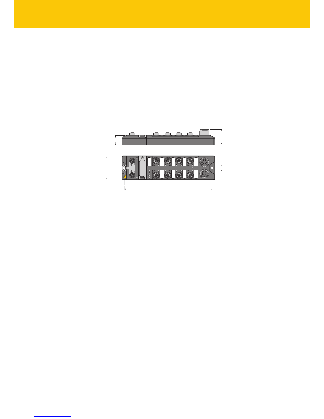
4.1 Device overview
218
230.5
C4C5C6C7
6.3
38.8
60.4
C0C1C2C3
24
30.2
X2
X1
P2
P1
Fig.1: Dimensions
4.1.1 Indication elements
The devices are provided with multi-color LEDs for displaying information:
n Power supply
n Group and bus errors
n Status
n Diagnostics
4.1.2 Operating elements
The devices are provided with the following operating elements:
n Rotary coding switches and DIP switch for setting the IP address
n SET button for activating the write accesses of the USB Host port functions
Page 11

V02.00 | 2018/08
11
4.2 Properties and features
n Glass fiber reinforced housing
n Shock and vibration tested
n Fully encapsulated module electronics
n Degree of protection IP65/IP67/IP69K
n Multiprotocol: EtherNet/IP™ device, Modbus TCP slave or PROFINET device
n Up to 128 bytes of user data per read/write cycle per channel as well as use of fragments for
larger data volumes
n Data interface for convenient use of the RFID functions
n 4 or 5-pin 7/8” plug connector for the power supply
n Two 4-pin M12 terminals for Ethernet
n Four channels with an M12 terminal for RFID
n Mixed operation of HF and UHF read/write heads
n Eight digital channels can be configured as 2 A pnp inputs or outputs
n Integrated Ethernet switch enables line topology
n 10 Mbps/100 Mbps transfer rate
n Integrated web server
n LEDs and diagnostics
4.3 Operating principle
When used as slaves, the RFID interfaces connect the RFID system with the higher-level controller system. The interfaces are provided with a fieldbus interface and fieldbus-independent I/O
electronics with an RFID interface. The interfaces can also process signals of sensors and actuators via eight configurable digital channels. The interfaces are provided with a multiprotocol
fieldbus interface for Modbus TCP, EtherNet/IP™ and PROFINET. The fieldbus interface connects
the interface to an (existing) fieldbus system as an EtherNet/IP™ device, Modbus TCP slave or
PROFINET device. During operation, the process data is exchanged between the fieldbus and
RFID system. The read/write heads are connected to the interfaces via the RFID interfaces.
When used as Modbus TCP master, the RFID interfaces connect the RFID system with other systems communicating via TCP/IP. The interfaces are provide with an Ethernet interface and RFID
interfaces.
The RFID system can be linked via the TCP/IP interface to a third-party system, such as an ERP
system. The read/write heads are connected to the interfaces via the RFID interfaces. The interfaces can also process signals of sensors and actuators via eight configurable digital channels.
Page 12

Product Description
12
Hans Turck GmbH & Co. KG | T +49 208 4952-0 | F +49 208 4952-264 | more@turck.com | www.turck.com
4.4 Functions and operating modes
The compact RFID interfaces transfer the data between the RFID level (read/write head and tag)
and the controller level. HF and UHF read/write heads can be connected to the RFID channels.
Parallel operation of HF and UHF read/write heads on the same device is also possible.
The devices can be used as an EtherNet/IP™ device, Modbus TCP Turck slave, or PROFINET RT
device. The devices can also be used as masters in the Modbus TCP fieldbus system.
The device enables the execution of different commands such as inventory (single-tag and
multitag applications), read, write and password protection. Additional functions are provided
for optimizing the speed, the self triggering of the system, as well as for backup and restore operations. In every write or read cycle, up to 128 bytes can be transferred on each channel to the
controller. The data must be fragmented in order to transfer more than 128 bytes.
Sensors and actuators can be connected to the configurable digital channels. Up to eight 3wire PNP sensors or four PNP DC actuators with a maximum output current of 2 A can be connected per output.
The device can take over autonomous controller and diagnostic functions in order to relieve
the load on the controller. The devices can be programmed using the IEC61131-3 compliant
CODESYS 3 programming software.
The TBEN-L…4RFID- 8DXP-CDS-WV block modules are provided with a complete WebVisu license.
4.4.1 Multiprotocol function
The I/O modules combine three Ethernet protocols in a single device:
n Modbus TCP
n EtherNet/IP™
n PROFINET
The Ethernet protocol used must be selected in the CODESYS project.
Manual protocol selection
The protocol must be defined manually in the CODESYS program. The other protocols only allow read access to the device. Manual protocol selection thus also provides an additional permanent locking feature.
4.4.2 Data transfer to the PLC
In every write or read cycle, up to 128 bytes can be transferred on each channel. The data must
be fragmented in order to transfer more than 128 bytes. The amount of data transferred per
read or write cycle can be set as follows for different Ethernet protocols:
PROFINET EtherNet/IP™ Modbus TCP
n 8 bytes
n 16 bytes (default setting)
n 32 bytes
n 64 bytes
n 128 bytes
n 16 bytes
n 64 bytes
n 128 bytes (default setting)
n 128 bytes (permanently set)
Adjustable fragment size:
n 8 bytes
n 16 bytes (default setting)
n 32 bytes
n 64 bytes
n 128 bytes
Page 13

V02.00 | 2018/08
13
4.4.3 RFID channels – Operating modes
Five different data interfaces can be selected for the RFID channels:
n HF compact
n HF extended
n HF bus mode
n UHF compact
n UHF extended
Different functions are available to the user, depending on the selected data interface.
HF compact mode
HF compact mode is suitable for transferring smaller data volumes of up to 128bytes (e.g. UID)
in single-tag applications.
HF extended mode
HF extended mode contains all the functions provided in HF compact mode. It is also possible
to transfer more than 128 bytes by fragmenting the data. The operating mode is suitable for
single-tag and multitag applications.
NOTE
Not all commands are supported in Multitag mode.
The user can set a command timeout to define the time for the execution of a command.
“HF extended” mode enables the use of Continuous mode for the repeated execution of an inventory, tag info, read or write command. In Continuous mode the read/write head executes
the commands autonomously. Different data is stored in the internal memory of the interface.
The memory operates as a FIFO memory.
Page 14

Product Description
14
Hans Turck GmbH & Co. KG | T +49 208 4952-0 | F +49 208 4952-264 | more@turck.com | www.turck.com
HF bus mode
In HF bus mode up to 32 bus-capable read/write heads per RFID channel can be connected to
the TBEN module. Depending on the number of connected read/write heads, an addition
power supply may be required. A power consumption analysis of the connected read/write
heads is required in order to determine the additional power supply required. Every connected
read/write head supplies a “Tag present” signal in HF bus mode. The HF bus mode can be used
for static applications because a command can only be processed by one read/write head at a
time.
TBEN-L…-4RFID-8DXP-…
VT2-FKM5-FKM5-FSM5
RFID connection cable
(e.g. RK4.5T-0.3-RS4.5T/S2503)
TN-M18-H1147/C53
TN-CK40-H1147/C53
TN-M30-H1147/C53
up to 32 per port
Fig.2: HF bus mode setup
The following read/write heads can be used for HF bus mode:
n TN-M18-H1147/C53
n TB-M18-H1147/C53
n TN-M30-H1147/C53
n TB-M30-H1147/C53
n TN-CK40-H1147/C53
n TNSLR-Q42TWD-H1147/C53
n TB-Q08-0.15-RS4.47T/C53
n TB-Q08-0.15-RS4.47T/C53
n TN-Q14-0.15-RS4.47T/C53
n TNSLR-Q80WD-H1147/C53
HF bus mode supports the HF read/write heads from firmware version Vx.90.
UHF compact mode
UHF compact mode enables up to 128 bytes of data to be transferred in single-tag applications
(e.g. EPC).
Page 15

V02.00 | 2018/08
15
UHF extended mode
UHF extended mode contains all the functions provided in UHF compact mode. It is also possible to transfer more than 128 bytes. The operating mode is suitable for single-tag and multitag applications. The user can set a command timeout to define the time for the execution of a
command.
UHF extended mode enables the use of presence sensing mode for the repeated execution of
an inventory, read or write command. In Presence sensing mode the read/write heads are automatically switched on or off and also carry out commands automatically. In this case, the read
data is stored in the internal memory of the interface. The memory operates as a FIFO memory.
4.4.4 RFID commands
The device can perform the following commands and functions. A complete description of the
commands is provided in the section “Setting”.
n Idle
n Inventory
n Read
n Write
n Write and verify
n Continuous mode
n Get data from buffer (Continuous mode)
n Continuous presence sensing mode (UHF)
n End Continuous (presence sensing) mode
n Read/write head identification
n HF read/write head off
n Tune HF read/write head
n Query HF read/write head address
n Set HF read/write head address
n Direct read/write head command
n Set tag password
n Set read/write head password
n Reset read/write head password
n Set tag protection
n Get HF tag protection status
n Set perma lock
n Tag info
n Kill UHF tag
n Restore settings of the UHF read/write head
n Backup settings of the UHF read/write head
n Query error/status of UHF read/write head
n Reset
4.4.5 Loop counter function
The loop counter function is provided for rapid command processing. The loop counter function only requires two PLC cycles to execute a command repeatedly (flow chart see p. [}232]).
This increments the loop counter to execute a command repeatedly. At least four PLC cycles
are required in conventional command processing. In order to execute a command repeatedly
with conventional command processing, a command has to be reset and then set again. The
loop counter function is provided for special commands. If the command was successfully executed, the command code is output in the response data.
Page 16

Product Description
16
Hans Turck GmbH & Co. KG | T +49 208 4952-0 | F +49 208 4952-264 | more@turck.com | www.turck.com
4.4.6 Configurable digital channels – Functions
The device is provided with eight digital channels, which can be configured as inputs or outputs according to the application requirements. Up to eight 3-wire PNP sensors or eight PNP
DC actuators with a maximum output current of 2 A can be connected per input or output.
4.4.7 USB host port
The device is provided with a USB host port for connecting USB memory sticks. The USB host
port is a USB2.0 A socket. The USB functions enable CODESYS applications and user data to be
saved, restored and transferred. The firmware of the devices can also be updated via the USB
interface. Memory expansion via the USB host port is not possible.
4.4.8 USB device port
The device is provided with a USB device port for connecting USB cables. The USB device port is
designed as a mini USB-B socket. The USB device port can be used as a service interface for the
device DTM or as a programming interface. The use of the USB device port requires an RNDIS
driver. This is automatically installed with the installation of the DTM.
4.4.9 Compatible CODESYS versions
The device is compatible with the following CODESYS versions:
CODESYS
programming environment
CODESYS
runtime
Firmware
update
CODESYS
package
3.5.8.10 3.5.8.10 1.0.1.0 1.0.1.0
3.5.12.10 3.5.11.20 1.1.4.0 1.1.4.0
4.5 Technical Accessories
Accessories for mounting, connecting and parameterizing can be found in product database or
the Accessories List for TBEN (D301367) under www.turck.com. The accessories are not part of
the scope of delivery.
Page 17

V02.00 | 2018/08
17
5 Mounting
Fasten the devices on a level, pre-drilled and grounded mounting surface.
Fasten the module on the mounting surface with the two M6 screws. The maximum
tightening torque for fastening the screws is 1.5Nm.
218 [5.58]
M6 (2x)
max. 1.5 Nm
Fig.3: Fixing a device on a mounting plate
Page 18
Mounting
18
Hans Turck GmbH & Co. KG | T +49 208 4952-0 | F +49 208 4952-264 | more@turck.com | www.turck.com
5.1 Grounding the device
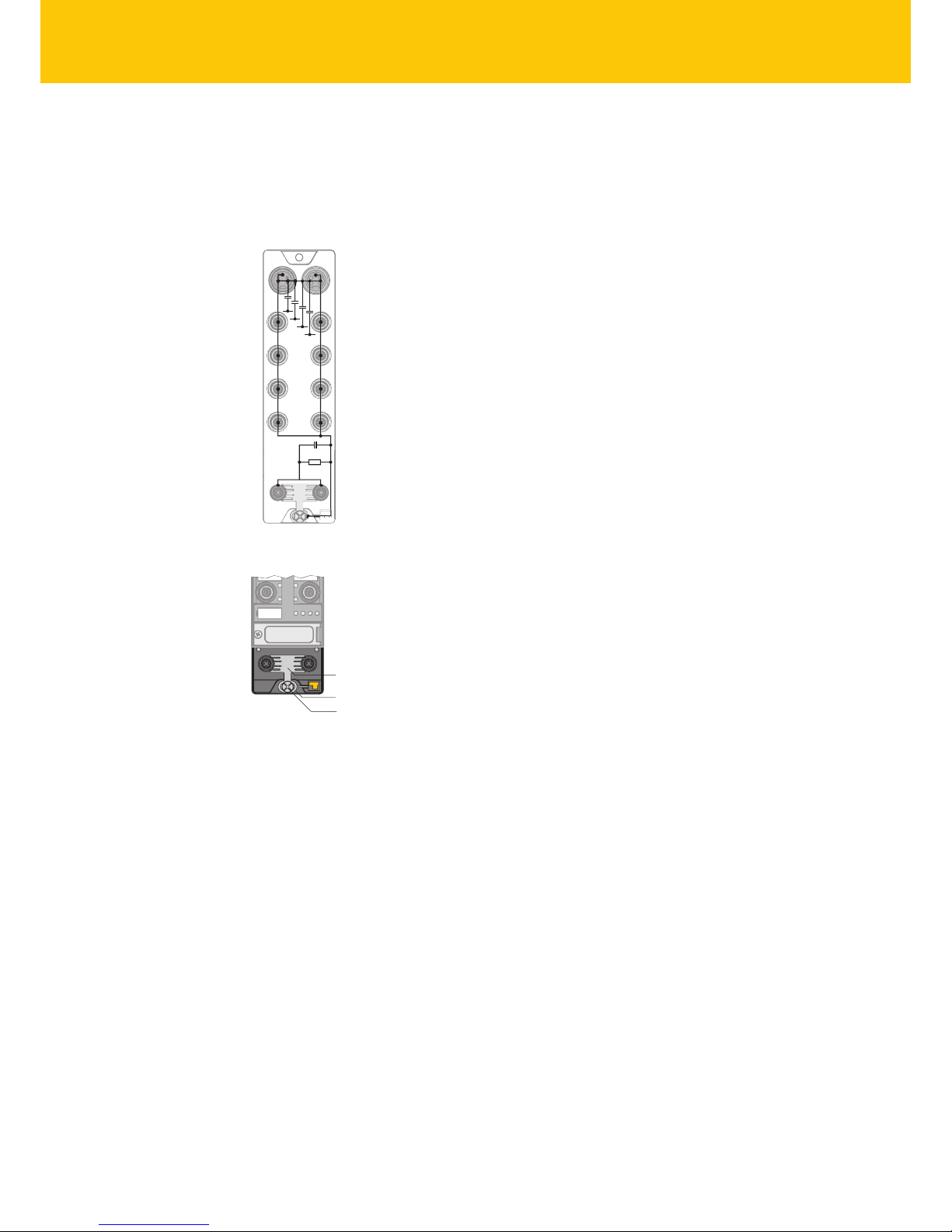
5.1.1 Grounding and shielding concept
The grounding and shielding concept of the TBEN-S modules enables the separate grounding
of the fieldbus and I/O sections.
1 nF
2,2 MΩ
X1
C0
C1
C2
C3
P1
X2
C4
C5
C6
C7
P2
4 x 15 nF
Fig.4: Equivalent circuit, shielding concept
1
2
3
Fig.5: Grounding components
The grounding clip (1) on the M12 plug connectors for the fieldbus connection (P1, P2) connects the shield of the fieldbus cables. The metal ring (2) is fitted underneath the grounding
strip and connects the functional ground of the 7/8” plug connectors (Pin 3) for the power supply with the functional ground of the M12 plug connectors (Pin 5) for connecting the read/
write heads, sensors and actuators. A metal screw (3) connects the device with the reference
potential of the system.
Page 19
V02.00 | 2018/08
19
5.1.2 Grounding the device (FG)
Grounding strip and metal ring are connected to each other. A fixing screw through the bottom
mounting hole of the module connects the shield of the fieldbus cables with the functional
ground of the power supply and connected devices as well as the reference potential of the
system. If a common reference potential is not required, remove the grounding clip to disconnect the fieldbus shield or fasten the module with a plastic screw.
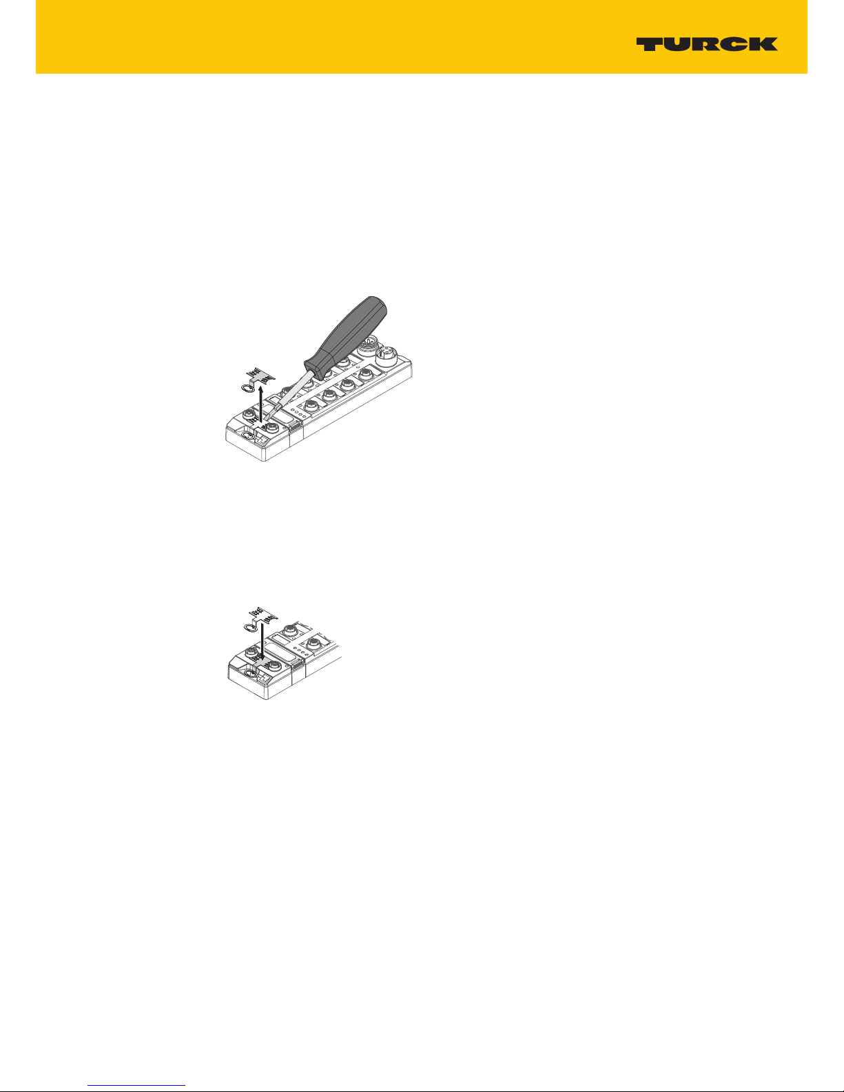
Removing the grounding clip
Lever up the grounding strip with a flat slot-head screwdriver and remove.
Fig.6: Removing the grounding clip
Mounting the grounding clip
Use a screwdriver to insert the grounding clip between the fieldbus connectors so that
contact is made with the metal housing of the plug connectors.
a The shield of the fieldbus cables is connected to the grounding clip.
Fig.7: Mounting the grounding clip
Page 20
Connection
20
Hans Turck GmbH & Co. KG | T +49 208 4952-0 | F +49 208 4952-264 | more@turck.com | www.turck.com
6 Connection
6.1 Connecting modules to Ethernet
The device is provided with an integrated autocrossing switch with two 4-pin M12 Ethernet
plug connectors for connecting to an Ethernet system. The maximum tightening torque is
0.6Nm.
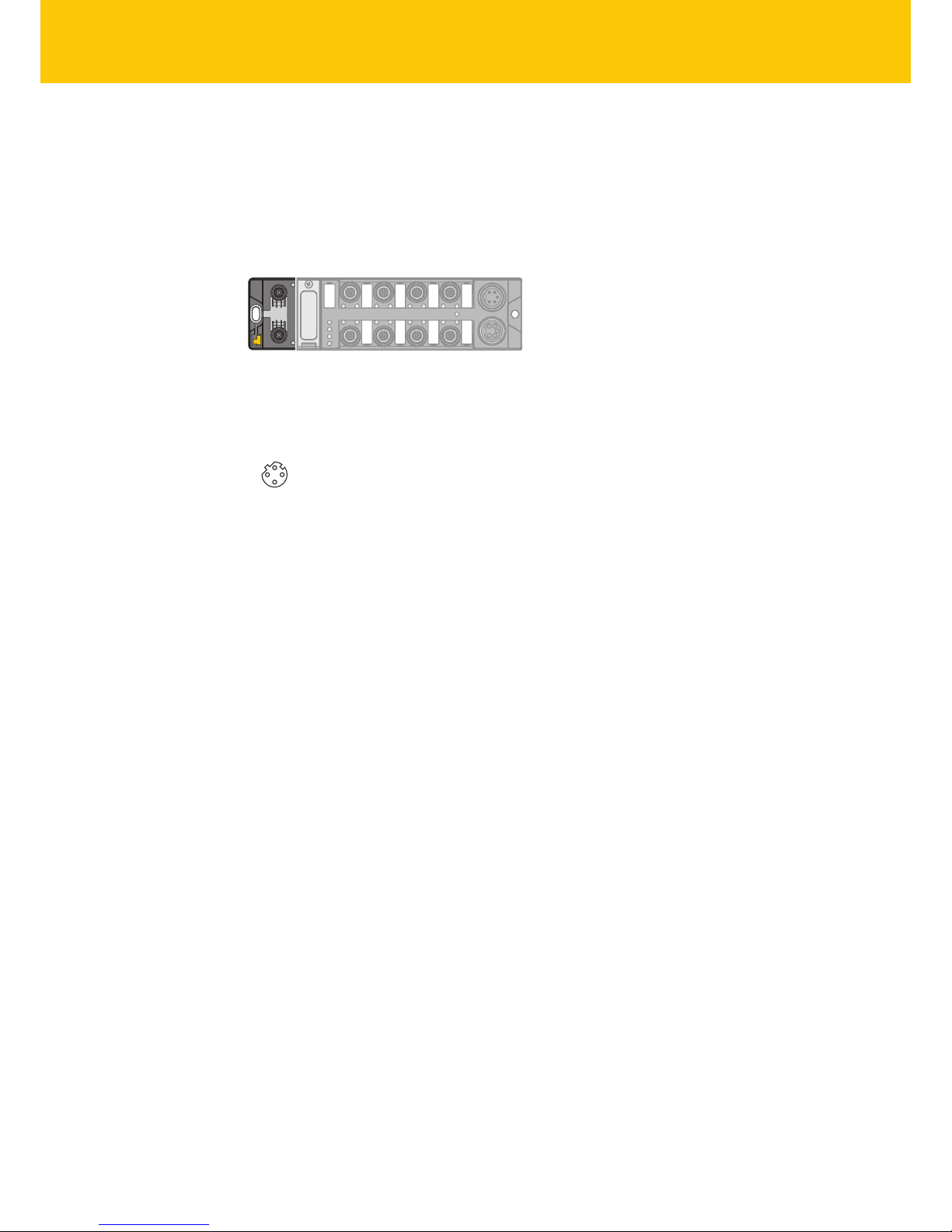
Fig.8: M12 Ethernet plug connectors for connecting the fieldbus
Connect the device to the fieldbus according to the pin layout below.
v
4
1
3
2
P1, P2
1 = TX +
2 = RX +
3 = TX –
4 = RX –
ange = FE
Fig.9: Pin layout of the Ethernet connections
Page 21
V02.00 | 2018/08
21
6.2 Connecting the power supply
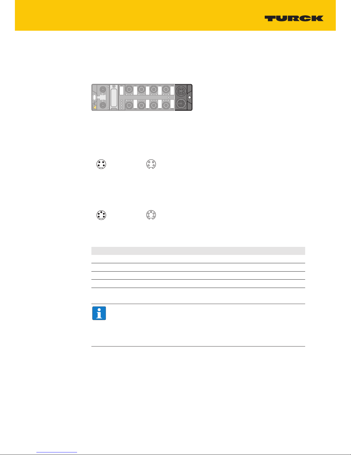
The device is provided with two 7/8” pin plug connectors for connecting the power supply. The
plug connectors are 4-pin (TBEN-L4) or 5-pin (TBEN-L5) connectors. V1 and V2 are electrically
isolated from each other. The maximum tightening torque is 0.8Nm.
Fig.10: 7/8” plug connectors for connecting the power supply
Connect the device to the power supply according to the pin layout below.
w v
123
4
1 RD = 24 VDC V2
2 GN = 24 VDC V1
3 WH = GND V1
4 BK = GND V2
1
2
3
4
X1 X2
Fig.11: TBEN-L4… – Pin layout of the power supply connections
1 BK = GND V2
2 BU = GND V1
3 GNYE = FE
4 BN = 24 VDC V1
5 WH = 24 VDC V2
3
452
1
w v
3
4
5
2
1
X1 X2
Fig.12: TBEN-L5… – Pin layout of the power supply connections
Connection Function
X1 Incoming voltage supply
X2 Routing the voltage to the next node
V1 System voltage: Supply voltage 1 (incl. electronics supply)
V2 Load voltage: Power supply 2
NOTE
The system voltage (V1) and the load voltage (V2) are supplied and monitored separately. If the voltage goes below the permissible lower limit, the sockets are disconnected according to the supply concept of the module type. If V2 goes below the
permissible minimum voltage, PWR LED changes from green to red. If V1 goes below
the permissible minimum, the PWR LED goes out.
Page 22

Connection
22
Hans Turck GmbH & Co. KG | T +49 208 4952-0 | F +49 208 4952-264 | more@turck.com | www.turck.com
6.3 Connecting RFID read/write heads
The device has four 5-pin M12 plug connectors for connecting RFID read/write heads. The maximum tightening torque is 0.8Nm.
Connect the read/write heads to the device as per the pin layout shown below.
4
1 3
2
5
v
1 = V
aux
1
2 = Data B
3 = GND V1
4 = Data A
5 = FE/Shield
Fig.13: RS485 – Pin layout of the read/write head connections
4
1
3
2
5
v
1 = BN (+)
2 = BK (Data)
3 = BU (GND)
4 = WH (Data)
5 = shield
Fig.14: …/S2500 connection cables – Pin layout of the read/write head connections
4
1
3
2
5
v
1 = BN (+)
2 = WH (Data)
3 = BU (GND)
4 = BK (Data)
5 = shield
Fig.15: …/S2501 connection cables – Pin layout of the read/write head connections
4
1 3
2
5
v
1 = RD (+)
2 = BU (Data)
3 = BK (GND)
4 = WH (Data)
5 = shield
Fig.16: …/S2503 connection cables – Pin layout of the read/write head connections
Page 23
V02.00 | 2018/08
23
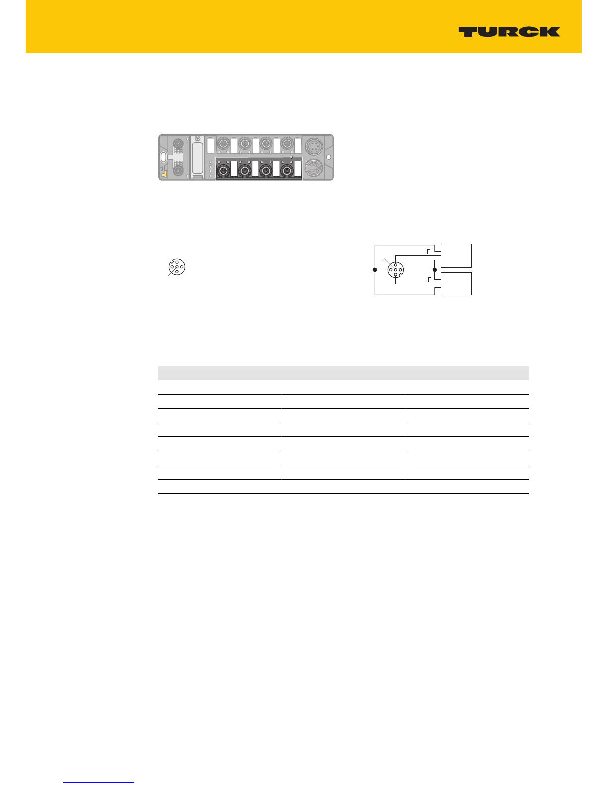
6.4 Connecting digital sensors and actuators
The device has four 5-pin M12 plug connectors for connecting digital sensors and actuators.
The maximum tightening torque is 0.8Nm.
Fig.17: M12 plug connector for connecting digital sensors and actuators
Connect the sensors and actuators to the device as per the pin layout below.
4
1
3
2
5
v
1 = V
aux
2
2 = Signal In/Out
3 = GND V2
4 = Signal In/Out
5 = FE
C2...C3
5 FE
4 BK
1 BN +
3 BU –
3 BU –
2 WH
v
C2…C3
Sensor
or
Actuator
Sensor
or
Actuator
Fig.18: Connections for digital sensors and actuators – Pin layout
Fig.19: Connections for digital sensors and actuators – Wiring diagram
The channels are assigned to the slots as follows:
Channel Slot Pin
DXP8 Ch8 C4 4
DXP9 Ch9 C4 2
DXP10 Ch10 C5 4
DXP11 Ch11 C5 2
DXP12 Ch12 C6 4
DXP13 Ch13 C6 2
DXP14 Ch14 C7 4
DXP15 Ch15 C7 2
Page 24

Commissioning
24
Hans Turck GmbH & Co. KG | T +49 208 4952-0 | F +49 208 4952-264 | more@turck.com | www.turck.com
7 Commissioning
Once the cables are connected and the power supply is switched on, the device is operational
automatically after a startup delay of 14 s.
The RFID interface can only be operated if an application is running on the device.
7.1 Setting the IP address
The IP address can be set via two decimal rotary coding switches and the DIP switch on the
device, via the web server or via the Turck Service tool.
7.1.1 Setting the IP address via switches on the device
The IP address can be set via two decimal rotary coding switches and the “Mode” DIP switch on
the device. The switches, together with the USB ports and the SET button, are located under a
cover.
5
4
3
2
1
0
9
8
7
6
5
4
3
2
1
0
9
8
7
6
2 1
3
ON
SRV
USB Host
Set
Mode
x 10
x 1
Fig.20: Switches for setting the IP address
Open the cover over the switches.
Set the required rotary coding switches to the required position according to the table
below.
Set the “Mode” DIP switch to the required position according to the table below.
Carry out a voltage reset.
NOTICE! IP67 or IP69K protection is not provided when the cover over the rotary coding
switches is opened. Device damage through penetrating foreign objects or liquids is possible. Close the cover securely over the switches.
Page 25

V02.00 | 2018/08
25
Addressing options
The IP address of the devices can be set in different ways. The following addressing options can
be selected via the switches on the device. Setting changes are activated after a voltage reset.
Setting option “MODE” DIP switch Rotary coding
switch
Description
Default address 0 00 IP address: 192.168.1.100
Subnet mask: 255.255.255.0
Gateway: 192.168.1.1
Rotary mode 0 1…99 In Rotary mode, the last byte of the IP address can
be set manually on the gateway. The other network
settings can be stored retentively in the gateway
memory and cannot be changed in Rotary mode.
Addresses 1…99 can be set.
DHCP mode 1 40 In DHCP mode, the complete IP address is assigned
automatically by a DHCP server in the network. The
subnet mask assigned by the DHCP server and the
default gateway address are stored retentively in
the gateway memory. DHCP supports three types
of IP address assignment:
n Automatic address assignment: The DHCP server
assigns a permanent IP address to the client.
n Dynamic address assignment: The IP address as-
signed by the server is always only reserved for a
specific period. After this time has elapsed or
after the explicit release by a client, the IP address is reassigned.
n Manual address assignment: A network adminis-
trator assigns an IP address to the client. In this
case DHCP is only used for the transfer of the assigned IP address to the client.
PGM mode 1 50 In PGM mode, the complete IP address is assigned
manually via the Turck Service tool, FDT/DTM or via
a web server. In PGM mode, the set IP address and
the subnet mask are stored in the gateway
memory. All network settings (IP address, subnet
mask, default gateway) are accepted by the internal
EEPROM of the module.
PGM-DHCP mode 1 60 In PGM-DHCP mode, the gateway transmits DHCP
requests until it is assigned a fixed IP address. The
DHCP client is automatically deactivated if an IP address is assigned to the gateway via the DTM or a
web server.
F_Reset 1 90 The F_Reset mode resets all device settings to the
default values and clears all data in the internal
flash memory of the device. The following values
are reset or deleted:
n IP address and subnet mask
n PROFINET device name
n CODESYS program
n Parameter
Restore 1 00 IP address: 192.168.1.254
Page 26

Commissioning
26
Hans Turck GmbH & Co. KG | T +49 208 4952-0 | F +49 208 4952-264 | more@turck.com | www.turck.com
7.1.2 Setting the IP address via the Turck Service Tool
The device is factory set to IP address 192.168.1.100 and does not have a PROFINET device
name. The IP address can be set via the Turck Service Tool. The Turck Service Tool is available
free of charge from www.turck.com.
Connect the device to a PC via the Ethernet interface.
Launch the Turck Service Tool.
Click “Search” or press F5.
Fig.21: Turck Service Tool – start screen
The Turck Service Tool displays the connected devices.
Fig.22: Turck Service Tool – found devices
Click the required device.
Click “Change” or press F2.
Page 27
V02.00 | 2018/08
27
Fig.23: Turck Service Tool – Selecting the device to be addressed
NOTE
Clicking the IP address of the device opens the web server.
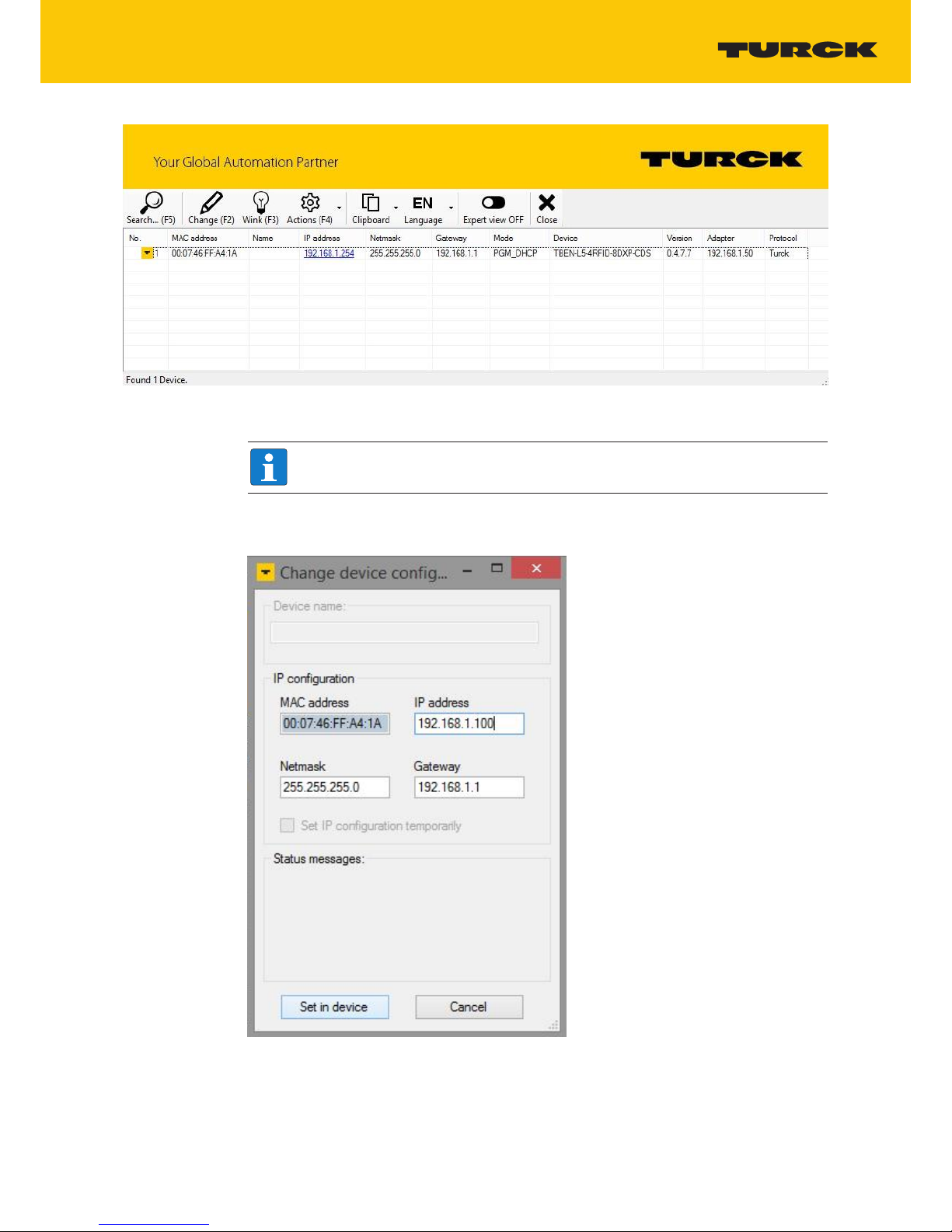
Change the IP address and if necessary the network mask and gateway.
Accept the changes by clicking “Set in device”.
Fig.24: Turck Service Tool – Changing the device configuration
Page 28
Commissioning
28
Hans Turck GmbH & Co. KG | T +49 208 4952-0 | F +49 208 4952-264 | more@turck.com | www.turck.com
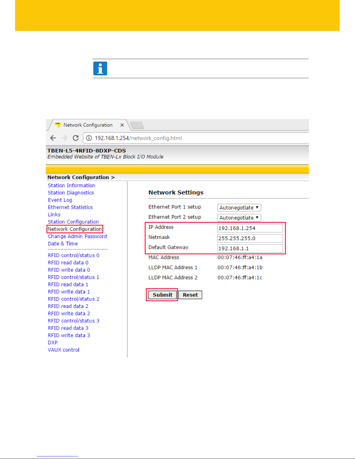
7.1.3 Setting the IP address via the web server
NOTE
The device must be in PGM mode in order to set the IP address via the web server.
Open the web server.
Log into the device as administrator.
Click “Network configuration”.
Change the IP address and if necessary also the subnet mask and default gateway.
Write the new IP address, subnet mask and default gateway via “Submit” to the device.
Fig.25: Setting the IP address via the web server
Page 29

V02.00 | 2018/08
29
7.2 Connecting the device to a Modbus master
In this example the “Tag present” bit is queried. This requires the network interface to be set up,
the hardware configured and the I/O mapping defined.
Hardware used
This example uses the following hardware components:
n Turck HMI TX507-P3CV01 (Modbus master)
n TBEN-L5-4RFID-8DXP-CDS block module (IP address: 192.168.1.100)
n TN-Q80-H1147 HF read/write head
Software used
This example uses the following software:
n CODESYS 3.5.8.1 (download free of charge from www.turck.com)
Prerequisites
n The programming software has been started.
n A new project has been created.
n The PLC has been added to the project.
Page 30
Commissioning
30
Hans Turck GmbH & Co. KG | T +49 208 4952-0 | F +49 208 4952-264 | more@turck.com | www.turck.com
7.2.1 Connecting the device with the controller
To connect the device to the controller, the following components must be added in CODESYS
first of all:
n Ethernet adapter
n Modbus TCP master
n Modbus TCP slave
Adding an Ethernet adapter
Right-click “Device (TX507-P3CV01)” in the project tree.
Fig.26: Project tree
Page 31

V02.00 | 2018/08
31
Select “Append device”.
Select an Ethernet adapter.
Click “Append device”.
a The Ethernet adapter appears as Ethernet (Ethernet) in the project tree.
Fig.27: Adding an Ethernet adapter
Page 32

Commissioning
32
Hans Turck GmbH & Co. KG | T +49 208 4952-0 | F +49 208 4952-264 | more@turck.com | www.turck.com
Adding a Modbus master
Right-click “Ethernet (Ethernet)” in the project tree.
Select “Append device”.
Double-click “Modbus TCP master”.
a The Modbus TCP master appears as “Modbus_TCP_Master” in the project tree.
Fig.28: Adding a Modbus master
Page 33

V02.00 | 2018/08
33
Adding a Modbus slave
Click Modbus slave in the project tree.
Press F2.
Enter a new device name (here: TBEN_L5_4RFID_CDS).
a The Modbus TCP slave appears as “Modbus_TCP_Slave” in the project tree.
Fig.29: Adding a Modbus slave
Page 34

Commissioning
34
Hans Turck GmbH & Co. KG | T +49 208 4952-0 | F +49 208 4952-264 | more@turck.com | www.turck.com
7.2.2 Renaming a Modbus slave
Click Modbus slave in the project tree.
Press F2.
Adapt the name of the slave in the application project tree (here: TBEN_L5_4RFID_CDS).
Fig.30: Renaming a Modbus slave
Page 35

V02.00 | 2018/08
35
7.2.3 Setting up network interfaces
Click “Device” Ò “Scan network”.
Select Modbus master (here: TX507-P3CV01) and confirm with OK.
Fig.31: Setting up a network interface to the Modbus master
Select the “PLC Settings” tab.
In the “Always refresh variables” drop-down menu, select “Activate 2 (always in the bus
cycle task)”.
Fig.32: Selecting the “Always refresh variables” option
Page 36

Commissioning
36
Hans Turck GmbH & Co. KG | T +49 208 4952-0 | F +49 208 4952-264 | more@turck.com | www.turck.com
Double-click “Ethernet”.
Enter the IP address of the Modbus master (here: 192.168.1.25).
Fig.33: Modbus master – Entering the IP address
Double-click the Modbus TCP slave.
In the “General” tab enter the IP address of the slave (here: 192.268.1,100
Fig.34: Modbus slave – Entering the IP address
Page 37

V02.00 | 2018/08
37
7.2.4 Setting Modbus channels (registers)
Set channel 0 (input data)
Double-click the Modbus TCP slave.
In the “Modbus slave channel” tab select Ò “Add channel”.
Enter the following values:
n Name of channel
n Access type: Read holding registers
n Offset: 0x0000
n Length: 64 registers (128 bytes)
Confirm with OK.
Fig.35: Setting the READ register
Page 38

Commissioning
38
Hans Turck GmbH & Co. KG | T +49 208 4952-0 | F +49 208 4952-264 | more@turck.com | www.turck.com
Set channel 1 (output data)
Double-click the Modbus TCP slave.
In the “Modbus slave channel” tab select Ò “Add channel”.
Enter the following values:
n Name of channel
n Access type: Write Holding Registers
n Offset: 0x0000
n Length: 64 registers (128 bytes)
Confirm with OK.
Fig.36: Setting the WRITE registers
Page 39

V02.00 | 2018/08
39
7.2.5 Setting the I/O mapping
To create I/O mapping the local I/Os must be added to the project and connected with the
Modbus master.
Right-click the name of the project in the project tree.
Select “Append device”.
Double-click “TBEN-Lx-4RFID-8DXP-CDS”.
a The local I/Os appear in the project tree.
Fig.37: Adding local I/Os to the project.
Page 40

Commissioning
40
Hans Turck GmbH & Co. KG | T +49 208 4952-0 | F +49 208 4952-264 | more@turck.com | www.turck.com
Attaching the Ethernet adapter to the local I/Os
Right-click “TBEN-Lx-4RFID-8DXP” in the project tree.
Select “Append device”.
Double-click “Ethernet”.
Fig.38: Attaching the Ethernet adapter to the local I/Os
Page 41

V02.00 | 2018/08
41
Attaching the Modbus TCP slave to the local I/Os
Right-click “Ethernet” in the project tree.
Select “Append device”.
Double-click “Modbus TCP slave device”.
Fig.39: Attaching the Modbus TCP slave to the local I/Os
Page 42

Commissioning
42
Hans Turck GmbH & Co. KG | T +49 208 4952-0 | F +49 208 4952-264 | more@turck.com | www.turck.com
Local I/Os – Setting the Ethernet interface
Double-click “TBEN-Lx-4RFID-8DXP-CDS” in the project tree.
In the “Communication” tab click the “Scan network” button.
Select TBEN-L5-4RFID-8DXP-CDS and confirm with “OK”.
Fig.40: Setting up the Ethernet interface to the connected TBEN-L5-4RFID-8DXP interface
Page 43

V02.00 | 2018/08
43
Select the “PLC Settings” tab.
In the “Always refresh variables” drop-down menu, select “Activate 2 (always in the bus
cycle task)”.
Fig.41: Setting the “Always refresh variables” option
Page 44

Commissioning
44
Hans Turck GmbH & Co. KG | T +49 208 4952-0 | F +49 208 4952-264 | more@turck.com | www.turck.com
Double-click “TBEN-Lx-4RFID-8DXP-CDS”.
Enter the IP address of the Modbus slave (here: 192.168.1.100).
Fig.42: Modbus master – Entering the IP address
Page 45

V02.00 | 2018/08
45
7.2.6 Writing the application to the device
To establish communication between Modbus master and TBEN-L…-4RFID-8DXP-CDS an executable application must be present in the device.
Right-click “Application” in the project tree.
Choose “Add object” Ò “Task configuration” in the context menu.
Fig.43: Adding a task for the application
Page 46

Commissioning
46
Hans Turck GmbH & Co. KG | T +49 208 4952-0 | F +49 208 4952-264 | more@turck.com | www.turck.com
Adding Program Organization Unit (POU)
This example uses a simple POU to map the “Tag present” bit to the inputs of the Modbus master.
Right-click “Application” in the project tree.
Choose “Add object” Ò “POU...” in the context menu.
Fig.44: Adding a POU
Page 47

V02.00 | 2018/08
47
Add the POU to the application: Click OK.
Fig.45: Adding the POU to the application
Page 48

Commissioning
48
Hans Turck GmbH & Co. KG | T +49 208 4952-0 | F +49 208 4952-264 | more@turck.com | www.turck.com
Mapping local I/Os of the Modbus master
Obtain the address of the “Tag present” bit from the mapping for the selected operating
mode (here: HF compact).
Fig.46: Address of the “Tag present” input bit in the local I/Os of the RFID interface
Page 49

V02.00 | 2018/08
49
Obtain the address for the “Tag present” output bit from the mapping for the slave
device.
Fig.47: Address for the output bit
Page 50

Commissioning
50
Hans Turck GmbH & Co. KG | T +49 208 4952-0 | F +49 208 4952-264 | more@turck.com | www.turck.com
Transferring the mapping to the POU
Fig.48: Transferring the mapping to the POU
Page 51

V02.00 | 2018/08
51
7.2.7 Connecting the device online with the controller
Select device.
Click Online Ò Login.
7.2.8 Reading out process data
The process data can be interpreted if the device is connected online with the controller.
Double-click the Modbus TCP slave.
Click the “Modbus TCP Slave I/O image” tab.
a The process data is displayed. In this example, the “Tag present” bit is set if a tag is
present in the detection range of the read/write head connected to channel 1.
Fig.49: Example: Process data
Page 52

Commissioning
52
Hans Turck GmbH & Co. KG | T +49 208 4952-0 | F +49 208 4952-264 | more@turck.com | www.turck.com
7.3 Connecting a device to an EtherNet/IP™ controller
In this example the “Tag present” bit is queried. This requires the network interface to be set up,
the hardware configured and the I/O mapping defined.
Hardware used
This example uses the following hardware components:
n Rockwell controller CompactLogix L30ER
n TBEN-L5-4RFID-8DXP-CDS block module (IP address: 192.168.1.100)
n TN-Q80-H1147 HF read/write head
Software used
This example uses the following software:
n Rockwell RS Logix
n CODESYS 3.5.8.1 (download free of charge from www.turck.com)
n EDS file for TBEN-4RFID-8DXP-CDS (download free of charge from www.turck.com)
Requirements
n The package file for TBEN-L…-4RFID-8DXP-CDS must be installed.
n The generic EDS file CDS_PN_DEVICE must be installed (downloaded free of charge from
www.turck.com).
Page 53

V02.00 | 2018/08
53
7.3.1 Configuring the device in CODESYS as an EtherNet/IP™ slave
Open CODESYS.
Create a new standard project.
Fig.50: Creating a new standard project in CODESYS
Page 54

Commissioning
54
Hans Turck GmbH & Co. KG | T +49 208 4952-0 | F +49 208 4952-264 | more@turck.com | www.turck.com
Select the “TBEN-Lx-4RFID-8DXP-CDS” block module.
Fig.51: Selecting TBEN-4RFID-8DXP-CDS
Page 55

V02.00 | 2018/08
55
This creates the device in the project tree.
Fig.52: TBEN-L5-4RFID-8DXP-CDS in the project tree
Page 56

Commissioning
56
Hans Turck GmbH & Co. KG | T +49 208 4952-0 | F +49 208 4952-264 | more@turck.com | www.turck.com
Adding an Ethernet adapter
Right-click “Device (TBEN-Lx-4RFID-8DXP-CDS)” in the project tree.
Select “Append device”.
Select an Ethernet adapter.
Click “Append device”.
Fig.53: Adding an Ethernet adapter
Page 57

V02.00 | 2018/08
57
Adding the EtherNet/IP™ slave
Right-click “Ethernet (Ethernet)” in the project tree.
Select “Append device”.
Select an “EtherNet/IP™ device”.
Click “Append device”.
Fig.54: Adding the EtherNet/IP™ slave
Page 58

Commissioning
58
Hans Turck GmbH & Co. KG | T +49 208 4952-0 | F +49 208 4952-264 | more@turck.com | www.turck.com
Assigning inputs and outputs
Right-click “EtherNet/IP™_Device (EtherNet/IP™ Device)” in the project tree.
Select “Append device”.
Example: Double-click “IN 1 WORD”.
Example: Double-click “OUT 1 WORD”.
Click “Append device”.
NOTE
The sockets defined as inputs in CODESYS correspond to the outputs in RSLogix and
vice versa.
Fig.55: Assigning inputs and outputs
Page 59

V02.00 | 2018/08
59
Inputs and outputs – Creating the mapping
Example: The “Tag present” bit has to be sent to the controller via an output byte.
Double-click the required operating mode in the project tree (here: HF compact).
Select the “HF compact I/O image” tab.
Find the internal device address of the “Tag present” bit from the I/O image for the selec-
ted operating mode (here: HF compact).
Fig.56: Internal address for the “Tag present” bit
Page 60

Commissioning
60
Hans Turck GmbH & Co. KG | T +49 208 4952-0 | F +49 208 4952-264 | more@turck.com | www.turck.com
Example: Double-click “OUT_1_WORD” in the project tree.
Assign the internal address for the “Tag present” bit to the output byte.
Fig.57: Mapping the I/O address
Page 61

V02.00 | 2018/08
61
7.3.2 Setting up the network interface
Click “Device” Ò “Scan network”.
Select TBEN-L5-4RFID-8DXP-CDS and confirm with OK.
Fig.58: Setting up the network interface
Page 62

Commissioning
62
Hans Turck GmbH & Co. KG | T +49 208 4952-0 | F +49 208 4952-264 | more@turck.com | www.turck.com
Select the “PLC Settings” tab.
In the “Always refresh variables” drop-down menu, select “Activate 1 (always in the bus
cycle task)”.
Fig.59: Setting the “Always refresh variables” option
Page 63

V02.00 | 2018/08
63
Double-click “Ethernet”.
Select the network interface.
Enter the address of the EtherNet/IP™ master (here: 192.168.0.100).
Fig.60: EtherNet/IP™ master – Entering the IP address
Page 64

Commissioning
64
Hans Turck GmbH & Co. KG | T +49 208 4952-0 | F +49 208 4952-264 | more@turck.com | www.turck.com
Connecting the device online
Click Online Ò Login.
Click the “Start” button.
The connection is now displayed in the project tree.
Fig.61: Display of the connection in CODESYS
Page 65

V02.00 | 2018/08
65
7.3.3 Installing an EDS file
The generic EDS file for the device can be downloaded free of charge from www.turck.com in
the package for TBEN-L…-CDS.
Include an EDS file: Click “Tools” Ò “EDS Hardware Installation Tool”.
Fig.62: Installing an EDS file
Page 66

Commissioning
66
Hans Turck GmbH & Co. KG | T +49 208 4952-0 | F +49 208 4952-264 | more@turck.com | www.turck.com
The wizard for the installation of EDS file is started.
Click “Next” to select the EDS file.
Fig.63: Wizard for the installation of EDS files
Page 67

V02.00 | 2018/08
67
Select the “Register an EDS file(s)” option and confirm with “Next”.
Fig.64: Selecting the “Register an EDS file(s)” option
Page 68

Commissioning
68
Hans Turck GmbH & Co. KG | T +49 208 4952-0 | F +49 208 4952-264 | more@turck.com | www.turck.com
Select an EDS file: Select a single file or folder (example: single file).
Enter a path for the memory location of the EDS file.
Confirm with “Next”.
a The installation wizard guides you through the further installation.
Fig.65: Selecting an EDS file
Page 69

V02.00 | 2018/08
69
7.3.4 Connecting the device with the controller
Right-click “I/O configuration” Ò “Ethernet”.
Click “New Module”.
Fig.66: Adding a new module
Page 70

Commissioning
70
Hans Turck GmbH & Co. KG | T +49 208 4952-0 | F +49 208 4952-264 | more@turck.com | www.turck.com
Select Turck under “Module Type Vendor Files”.
Select the generic ESD file for “CDS3 EtherNet/IP Slave”.
Confirm selection with “Create”.
Fig.67: Selecting the generic ESD file for Turck Codesys-EtherNet/IP™ slave
Assign a module name.
Enter the IP address of the device (example: 192.168.1.100).
Fig.68: Setting the module name and IP address
Page 71

V02.00 | 2018/08
71
The device appears in the project tree.
Fig.69: TBEN-L…-4RFID-8DXP in the project tree
Page 72

Commissioning
72
Hans Turck GmbH & Co. KG | T +49 208 4952-0 | F +49 208 4952-264 | more@turck.com | www.turck.com
7.3.5 Reading out process data
In online mode, the “Tag present” bit is displayed in the monitoring table.
Fig.70: “Tag present” bit in the monitoring table
Page 73

V02.00 | 2018/08
73
7.4 Connecting a device to a Siemens controller
In this example the “Tag present” bit is queried. This requires the network interface to be set up,
the hardware configured and the I/O mapping defined.
Hardware used
This example uses the following hardware components:
n Siemens S7-1500 controller with CPU 1513-1 PN
n TBEN-L5-4RFID-8DXP-CDS block module (IP address: 192.168.1.100)
n TN-Q80-H1147 HF read/write head
Software used
This example uses the following software:
n CODESYS 3.5.8.1 (download free of charge from www.turck.com)
n SIMATIC STEP7 Professional V13 (TIA Portal)
n Generic GSDML file for PROFINET devices (available as download free of charge from
www.turck.com)
Requirements
n The package file for TBEN-L…-4RFID-8DXP-CDS must be installed.
Page 74

Commissioning
74
Hans Turck GmbH & Co. KG | T +49 208 4952-0 | F +49 208 4952-264 | more@turck.com | www.turck.com
7.4.1 Configuring the device in CODESYS as a PROFINET device
Open CODESYS.
Create a new standard project.
Fig.71: Creating a new standard project in CODESYS
Page 75

V02.00 | 2018/08
75
Select the “TBEN-Lx-4RFID-8DXP-CDS” block module.
Fig.72: Selecting the master device
Page 76

Commissioning
76
Hans Turck GmbH & Co. KG | T +49 208 4952-0 | F +49 208 4952-264 | more@turck.com | www.turck.com
This creates the device in the project tree.
Fig.73: TBEN-L5-4RFID-8DXP-CDS in the project tree
Page 77

V02.00 | 2018/08
77
Adding an Ethernet adapter
Right-click “Device (TBEN-Lx-4RFID-8DXP-CDS)” in the project tree.
Select “Append device”.
Select an Ethernet adapter.
Click “Append device”.
Fig.74: Adding an Ethernet adapter
Page 78

Commissioning
78
Hans Turck GmbH & Co. KG | T +49 208 4952-0 | F +49 208 4952-264 | more@turck.com | www.turck.com
Attaching the PROFINET device
Right-click “Ethernet (Ethernet)” in the project tree.
Select “Append device”.
Select “Profinet Device”.
Click “Append device”.
Fig.75: Attaching the PROFINET device
Page 79

V02.00 | 2018/08
79
Assigning inputs and outputs
Right-click “Profinet_Device (Profinet Device)” in the project tree.
Select “Append device”.
Example: Double-click “IN 1 BYTE”.
Example: Double-click “OUT 1 BYTE”.
Click “Append device”.
NOTE
The sockets defined as inputs in CODESYS correspond to the outputs in the TIA
Portal and vice versa.
Fig.76: Attaching inputs and outputs
Page 80

Commissioning
80
Hans Turck GmbH & Co. KG | T +49 208 4952-0 | F +49 208 4952-264 | more@turck.com | www.turck.com
Inputs and outputs – Creating the mapping
Example: The “Tag present” bit has to be sent to the controller via an output byte.
Double-click the required operating mode in the project tree (here: HF compact).
Select the “HF compact I/O image” tab.
Find the internal device address of the “Tag present” bit from the I/O image for the selec-
ted operating mode (here: HF compact).
Fig.77: Internal address for the “Tag present” bit
Page 81

V02.00 | 2018/08
81
Example: Double-click “OUT_1_BYTE” in the project tree.
Assign the internal address for the “Tag present” bit to the output byte.
Fig.78: Mapping the I/O address
Page 82

Commissioning
82
Hans Turck GmbH & Co. KG | T +49 208 4952-0 | F +49 208 4952-264 | more@turck.com | www.turck.com
7.4.2 Setting up the network interface
Click “Device” Ò “Scan network”.
Select TBEN-L5-4RFID-8DXP-CDS and confirm with OK.
Fig.79: Setting up the network interface
Page 83

V02.00 | 2018/08
83
Select the “PLC Settings” tab.
In the “Always refresh variables” drop-down menu, select “Activate 2 (always in the bus
cycle task)”.
Fig.80: Setting the “Always refresh variables” option
Page 84

Commissioning
84
Hans Turck GmbH & Co. KG | T +49 208 4952-0 | F +49 208 4952-264 | more@turck.com | www.turck.com
Double-click “Ethernet”.
Select the network interface.
Enter the IP address of the Modbus master (here: 192.168.0.254).
Fig.81: Modbus master – Entering the IP address
Page 85

V02.00 | 2018/08
85
Connecting the device online
Click Online Ò Login.
Click the “Start” button.
a The connection is now displayed in the project tree.
Fig.82: Display of the connection in CODESYS
Page 86

Commissioning
86
Hans Turck GmbH & Co. KG | T +49 208 4952-0 | F +49 208 4952-264 | more@turck.com | www.turck.com
7.4.3 Connecting a device to a Siemens controller in the TIA Portal
Create a new project TIA Portal.
Fig.83: Creating a new project TIA Portal
Add a controller (here: CPU 1513-1 PN).
Fig.84: Adding a controller
Page 87

V02.00 | 2018/08
87
Include the Turck Codesys device in the project. To do this, select the generic GSDML file
“CDS3 PN Device” from the “Turck” folder.
Fig.85: Adding the Turck Codesys device
Page 88

Commissioning
88
Hans Turck GmbH & Co. KG | T +49 208 4952-0 | F +49 208 4952-264 | more@turck.com | www.turck.com
TBEN-L…-4RFID-8DXP-CDS – Assigning the IP address and PROFINET device name
Assign the IP address and PROFINET device name if necessary via the Turck Service Tool.
Enter IP address and PROFINET name in the TIA Portal (Device configuration Ò Proper-
ties Ò General Ò Ethernet address.
Fig.86: Assigning the IP address and PROFINET device name in the TIA Portal
Page 89

V02.00 | 2018/08
89
Assigning inputs and outputs
NOTE
The sockets defined as inputs in CODESYS correspond to the outputs in the TIA
Portal and vice versa.
Example: Assign IN 1 Byte and OUT 1 Byte from the Hardware catalog to the device.
Fig.87: Assigning the inputs and outputs in the TIA Portal
Page 90

Commissioning
90
Hans Turck GmbH & Co. KG | T +49 208 4952-0 | F +49 208 4952-264 | more@turck.com | www.turck.com
Creating the monitoring table
The process data (in this case: the set “Tag present” bit) can be visualized via monitoring tables.
Creating a new monitoring table.
Fig.88: Creating the monitoring table
Page 91

V02.00 | 2018/08
91
Loading the configuration in the controller
Load the configuration in the controller.
Fig.89: Loading the configuration in the controller
Page 92

Commissioning
92
Hans Turck GmbH & Co. KG | T +49 208 4952-0 | F +49 208 4952-264 | more@turck.com | www.turck.com
7.4.4 Reading out process data
In online mode, the “Tag present” bit is displayed in the monitoring table.
Fig.90: “Tag present” bit in the monitoring table
The successful connection is now displayed in the project tree in CODESYS.
Fig.91: Successfully established connection – Display in CODESYS
Page 93

V02.00 | 2018/08
93
7.5 Starting the device as the Modbus master
In this example the “Tag present” bit is queried. This requires the network interface to be set up,
the hardware configured and the I/O mapping defined.
Hardware used
This example uses the following hardware components:
n TBEN-L5-4RFID-8DXP-CDS block module (IP address: 192.168.1.100)
n TBEN-2RFID-4DXP block module (IP address: 192.168.1.20)
n TN-Q80-H1147 HF read/write head
Software used
This example uses the following software:
n CODESYS 3.5.8.1 (download free of charge from www.turck.com)
Requirements
n The package file for TBEN-L…-4RFID-8DXP-CDS must be installed.
Page 94

Commissioning
94
Hans Turck GmbH & Co. KG | T +49 208 4952-0 | F +49 208 4952-264 | more@turck.com | www.turck.com
Defining the device as master in CODESYS
Open CODESYS.
Create a new standard project.
Fig.92: Creating a new standard project in CODESYS
Page 95

V02.00 | 2018/08
95
Select the “TBEN-Lx-4RFID-8DXP-CDS” block module as master device.
Fig.93: Selecting the master device
Page 96

Commissioning
96
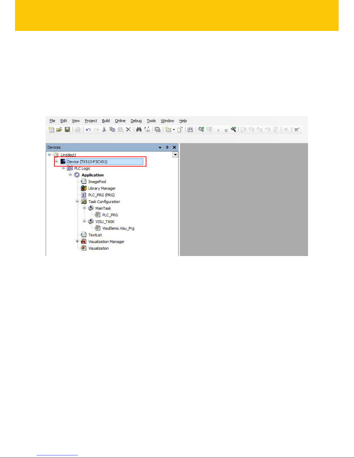
Hans Turck GmbH & Co. KG | T +49 208 4952-0 | F +49 208 4952-264 | more@turck.com | www.turck.com
This creates the device in the project tree.
Fig.94: TBEN-L5-4RFID-8DXP-CDS in the project tree
Page 97

V02.00 | 2018/08
97
Adding an Ethernet adapter
Right-click “Device (TBEN-Lx-4RFID-8DXP-CDS)” in the project tree.
Select “Append device”.
Select an Ethernet adapter.
Click “Append device”.
Fig.95: Adding an Ethernet adapter
Page 98

Commissioning
98
Hans Turck GmbH & Co. KG | T +49 208 4952-0 | F +49 208 4952-264 | more@turck.com | www.turck.com
Adding a Modbus master
Right-click “Ethernet (Ethernet)” in the project tree.
Select “Append device”.
Double-click “Modbus TCP master”.
a The device appears as “Modbus_TCP_Master” in the project tree.
a Modbus slaves can be connected to the Modbus master.
Fig.96: Adding a Modbus master
Page 99

V02.00 | 2018/08
99
7.5.1 Setting up the network interface
Double-click “Device (TBEN-L5-4RFID-8DXP-CDS” in the project tree.
Choose the “Communication” tab.
Click “Scan network”.
Select TBEN-L and press OK or double-click to confirm.
Fig.97: Adding the network interface
Page 100

Commissioning
100
Hans Turck GmbH & Co. KG | T +49 208 4952-0 | F +49 208 4952-264 | more@turck.com | www.turck.com
Select the “PLC Settings” tab.
In the “Always refresh variables” drop-down menu, select “Activate 2 (always in the bus
cycle task)”.
Fig.98: Selecting the “Always refresh variables” option
 Loading...