

Page 1

OPERATING
INSTRUCTIONS
CONTACTLESS
QR24 ENCODERS
WITH CANOPEN
INTERFACE
Sense it! Connect it! Bus it! Solve it!
Page 2
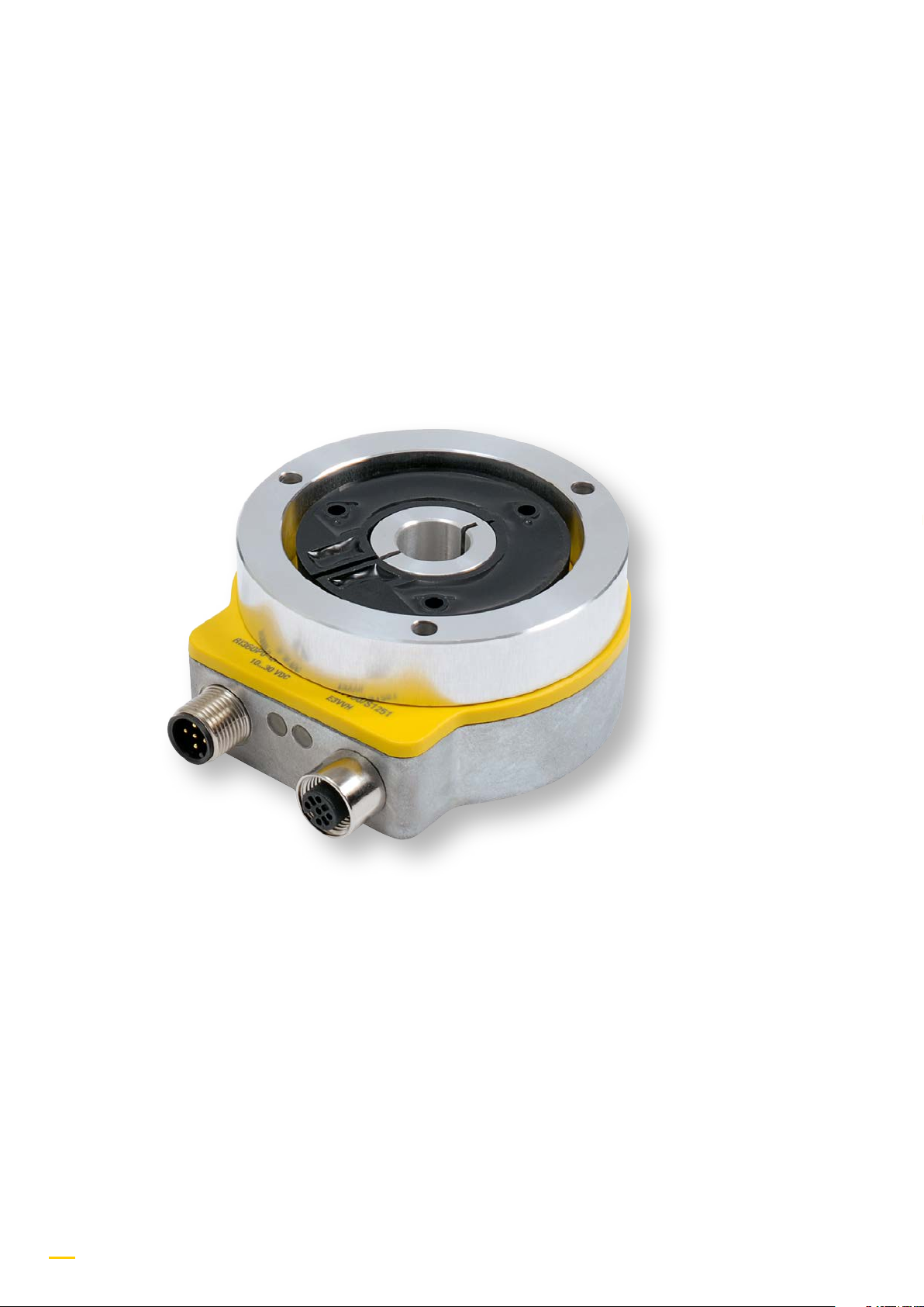
QR24 Encoder with CANopen Interface
2
Hans Turck GmbH & Co. KG • Tel. +49 208 4952-0 • Fax +49 208 4952-264
Page 3
Contactless Ri-QR24 encoders – with CANopen interface
1 About this manual ...................................................................................................................... 4
1.1 Target groups .............................................................................................................................. 4
1.2 Explanation of symbols ............................................................................................................. 4
1.3 Other documents ........................................................................................................................ 4
1.4 Feedback on this manual .......................................................................................................... 4
2 Notes on the product ................................................................................................................. 5
2.1 Product identication (type key) ............................................................................................. 5
2.2 Scope of delivery ........................................................................................................................ 6
2.3 Legal requirements .................................................................................................................... 6
2.4 Manufacturer and service ......................................................................................................... 6
3 For your safety
3.1 Intended use ................................................................................................................................ 6
3.2 Obvious misuse ........................................................................................................................... 6
3.3 General safety instructions ....................................................................................................... 6
4 Product description .................................................................................................................... 7
4.1 Device view .................................................................................................................................. 7
4.2 Function principles ..................................................................................................................... 8
4.3 Delivery condition ...................................................................................................................... 8
4.4 Display elements ........................................................................................................................ 8
4.5 Connection assignments ........................................................................................................... 10
4.6 Terminating resistor ................................................................................................................... 10
5 Assembly ...................................................................................................................................... 11
6 Conguration .............................................................................................................................. 12
6.1 Objects 1000h – 1FFFh (communication proles) ............................................................... 12
6.2 Variables PDO mapping ............................................................................................................ 23
6.3 Objects 2000h – 2FFFh (manufacturer specications) ....................................................... 28
6.4 Objects 6000h – 6FFFh (default device parameters) ........................................................... 31
6.5 LSS services DS 305 V2.0 ........................................................................................................... 40
6.6 Network management ............................................................................................................... 41
7 Accessories (assembly accessories and position elements) .............................................. 42
8 Technical information ................................................................................................................ 44
9 Service........................................................................................................................................... 45
10 Repairs .......................................................................................................................................... 45
11 Device returns ............................................................................................................................. 45
12 Disposal ........................................................................................................................................ 45
more@turck.com • www.turck.com • 2018/01
3
Page 4
QR24 Encoder with CANopen interface –
General information
1 About this manual
This manual describes the setup, the functions and use of the product and helps you to operate the product for its intended use. Read
these instructions carefully prior to using the product. This will prevent the risk of personal injury and damage to property. Keep these
instructions safely during the service life of the product. If the product is passed on, pass on these instructions as well.
1.1 Target groups
This document is written for specially trained personnel and must be read carefully by anyone who is charged with the mounting, commissioning, operation, maintenance, disassembly or disposal of the device.
1.2 Explanation of symbols
The following symbols are used in this manual:
WARNING
WARNING denotes a possibly hazardous situation with medium risk, which could result in fatality or severe injury if
not prevented.
NOTE
In connection with WARNING, you will find tips, recommendations, and important information. These notes will
simplify your work, contain information about specific steps to be taken, and help prevent additional work due to
incorrect procedures.
1.3 Other documents
You will find the following supporting documentation in addition to this document online at www.turck.com:
■ Data sheet
1.4 Feedback on this manual
We make every effort to ensure that these instructions are as informative and as clear as possible. If you have any suggestions for improving the design or if some information is missing in the document, please send your suggestions to techdoc@turck.com.
4
Hans Turck GmbH & Co. KG • Tel. +49 208 4952-0 • Fax +49 208 4952-264
Page 5
QR24 Encoder with CANopen interface –
Notes on the product
2 Notes on the product
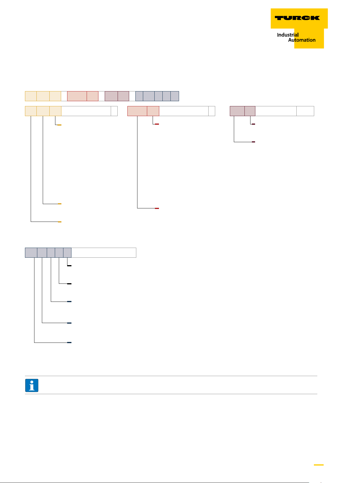
2.1 Product identication (type key)
Ri 360 P1 – QR24 M0 – CN X4 – 2 H1 1 5 0
Ri 360 P1
2 H1 1 5 0
Operating principle
Positioning element/
shaft diameter
P0 without positioning
element
P1 P1-Ri-QR24/20 mm
P2 P2-Ri-QR24/14 mm
P3 P3-Ri-QR24/12 mm
P4 P4-Ri-QR24/10 mm
P5 P5-Ri-QR24/6 mm
P6 P6-Ri-QR24 / /"
P7 P7-Ri-QR24 / /"
P8 P8-Ri-QR24 / -
Measuring range
360 360°
Operating principle
Ri Rotatory inductive
Electrical connection
Assignment
0 Standard
–
QR24 M1
Housing style
Alu protective unit
M0 without alu
protective unit
M1 with alu
protective unit
M2 Set M2-QR24
(M1-QR24 +
SP1-QR24)
M3 Set M3-QR24
(M1-QR24 +
SP2-QR24)
M4 Set M4-QR24
(M1-QR24 +
SP3-QR24)
Housing style
QR24
–
CN X4
Electrical version
Number of LEDs
X4 4 x LED
CANopen interface
CN CANopen
–
Number of contacts
5 5-pole
Connector type
1 straight
Connector type
H1 connector M12 x 1
Number of connectors
2 2 x connector
NOTE
The sensor, the assembly elements, and the positioning element can be ordered as a set or individually.
more@turck.com • www.turck.com • 2018/01
5
Page 6

QR24 Encoder with CANopen interface –
Notes on the product
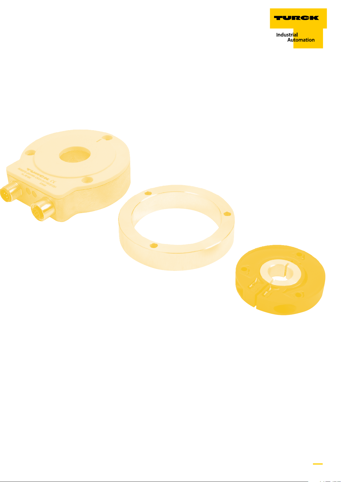
2.2 Scope of delivery
The following items are included in the scope of delivery:
■ Contactless QR24 encoder
■ Assembly aid
■ Short instructions
■ VZ 3 screw plug
■ Optional: positioning element and mounting element
2.3 Legal requirements
The device is subject to the following EU directives:
■ 2004/108/EC (Electromagnetic compatibility)
2.4 Manufacturer and service
Turck supports you in your projects – from the initial analysis right through to the commissioning of your application. The Turck product
database offers you several software tools for programming, configuring or commissioning, as well as data sheets and CAD files in many
export formats. You can access the Product Database directly via the following address:
www.turck.de/products
For further inquiries in Germany contact the Sales and Service Team on:
Sales: +49 (0) 208 4952-380
Technical: +49 (0) 208 4952-390
For overseas inquiries contact your national Turck representative.
Hans Turck GmbH & Co. KG
Witzlebenstraße 7
45472 Mülheim an der Ruhr
Germany
3 For your safety
The product is designed according to the state of the art technology. Residual hazards, however, still exist. Observe the following warnings and safety regulations in order to prevent danger to persons and property. Turck accepts no liability for damage caused by failure to
observe these warnings and safety instructions.
3.1 Intended use
The devices are designed for installation in large-scale industrial plants and equipment and for use in industrial automation applications.
The encoder measures turning angles across a 360° angle range. The devices must only be used as described in these instructions. Any
other use is not in accordance with the intended use; Turck accepts no liability for any resulting damage.
3.2 Obvious misuse
The devices are not safety components and must not be used for the protection of persons or property.
3.3 General safety instructions
The device must only be fitted, installed, operated and maintained by trained and qualified personnel.
6
Hans Turck GmbH & Co. KG • Tel. +49 208 4952-0 • Fax +49 208 4952-264
Page 7
QR24 Encoder with CANopen interface –
For your safety
4 Product description
The encoder measures turning angles across a 360° angle range. All parameters are stored in the internal parameter memory.
Features:
■ 360° angle sensor
■ High resolution and accuracy
■ CANopen interface in compliance with CiA DS-301, device profile CiA 406 3.1
■ Baud rates between 10 kbps and 1 Mbps
■ Sampling rate of typ. 1 kHz
■ Functions:
– One TPDO (RTR, cyclic, event-controlled, synchronised)
– SYNC consumer (synchronised transmission of TPDO after receipt of SYNC telegram)
– Failure monitoring via heartbeat or node-guarding/life-guarding
– Freely configurable limit frequency (digital filter)
– Robust, easy to assemble plastic housing
– Suitable for industrial applications
– Temperature range: -25…+85°C
– Housing protection type: IP68/IP69K
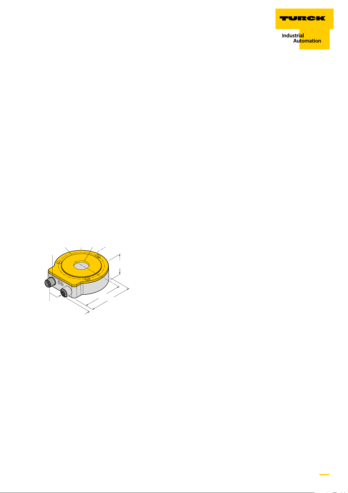
4.1 Device view
LED
M12 x 1
Fig. 1: Device view
ø 78 ø 22 ø 4.3 ø 65
24
42.3
81
10
more@turck.com • www.turck.com • 2018/01
7
Page 8
QR24 Encoder with CANopen interface –
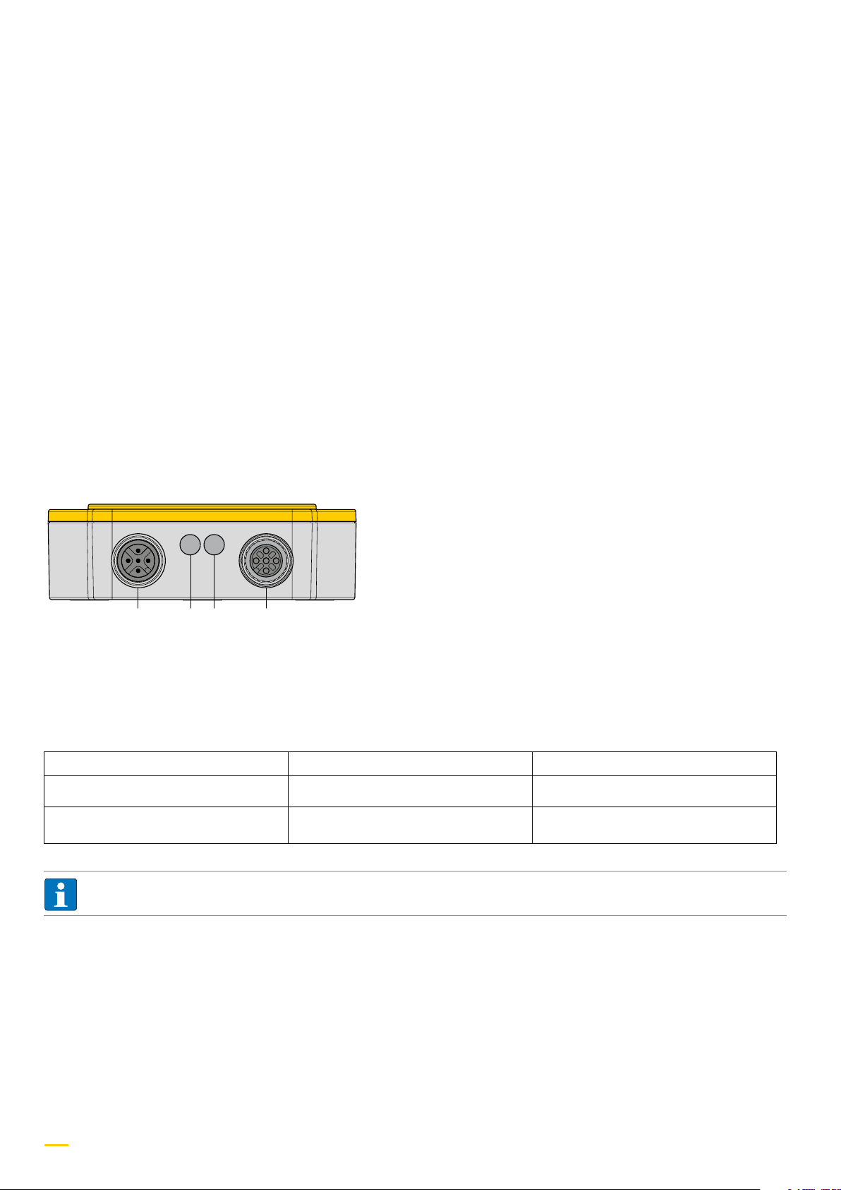
CAN-IN ERR/RUN PWR/SIG CAN-OUT
Product description
4.2 Function principle
The metering principle of the encoders is based on the inductive RLC coupling, which offers significant advantages in comparison with
optical or magnetic metering principles. The sensor contains emitter and receiver coil systems in the form of PCB coils. The emitter coils are
energised in a high frequency alternating field, and consummate an inductive RLC coupling in conjunction with the positioning element, the
so-called resonator. As a result, the positioning element is also inductively coupled with the receiver coils to pinpoint its exact position.
4.3 Delivery condition
At the time of delivery, the sensor comes with the following basic default settings:
■ Node ID: 0x03
■ Baud rate 125 kHz
■ Internal terminating resistor deactivated
■ TPDO1 event time: 100 ms
■ TPDO1 activated
■ TPDO asynchronous mode
4.4. Display elements
Fig. 2: LED arrangement
The encoder comes with an LED status display for the following states:
PWR LED
Colour/Status Status Description
OFF No operating voltage The device is not ready
Green Operating voltage OK The device is ready
NOTE
The PWR LED will respond at as little as 5 V, and is therefore not an indicator for having reached the operating voltage of 10…30 V.
8
Hans Turck GmbH & Co. KG • Tel. +49 208 4952-0 • Fax +49 208 4952-264
Page 9

QR24 Encoder with CANopen interface –
Product description
Run LED
Colour/Status Status Description
Green – fast flashing LSS status The device is in LSS operation (intermittently
flashing Error LED)
Green – On short flash Stopped Data transfer was stopped
Green – slow flashing Pre-operational The data transfer is in preparation
Green – continuously lit Operational The device is ready
Sig LED
Colour/Status Status Description
OFF RLC coupling OK The device is functioning correctly.
Yellow – continuously lit RLC coupling is weak The device is working with reduced accu-
rac y.
Yellow – flashing No RLC coupling The device is not functioning.
Error LED (ERR)
Colour/Status Status Description
OFF No error The device is functioning correctly
Red – flashing: LSS status The device is in LSS operation (intermittently
flashing RUN LED)
Red – Two short flashes Guard event occurrence A guard event (NMT slave or master) or
heartbeat event has occurred
Red – Three short flashes SYNC error The SYNC message was not received within
the preconfigured cycle time (see also ob-
ject 0x1006)
Red – continuously lit Bus deactivated The CAN controller was deactivated by the
bus
more@turck.com • www.turck.com • 2018/01
9
Page 10

31
QR24 Encoder with CANopen interface –
Connection assignment
4.5 Connection assignment
The sensor comes equipped with a CAN input connection and a CAN output connection in accordance with CiA DR-303-1.
Plug connector M12 x 1
Pin Signal Assignment
CAN-IN
2
1 CAN_SHLD Shield
5
4
2 CAN_V+ Supply voltage (+24 VDC)*
CAN-OUT 3 CAN_GND GND/0 V/V-
*) UL marking requires an approved power supply with energy limitation (UL 61010-1) or with Class 2 according to National Electric Code
(USA) / Canadian Electric Code.
2
1
5
3
4
4 CAN_H CAN_H bus line
5 CAN-L CAN_L bus line
4.6 Terminating resistor
An integrated terminating resistor can be activated as needed. (See object 0x2102).
10
Hans Turck GmbH & Co. KG • Tel. +49 208 4952-0 • Fax +49 208 4952-264
Page 11
QR24 Encoder with CANopen interface –
A
0.6...0.8 Nm
6
B
6
2
1
5
4
3
2.5
A
C
0.6...0.8 Nm
SP2-QR24
!
Assembly
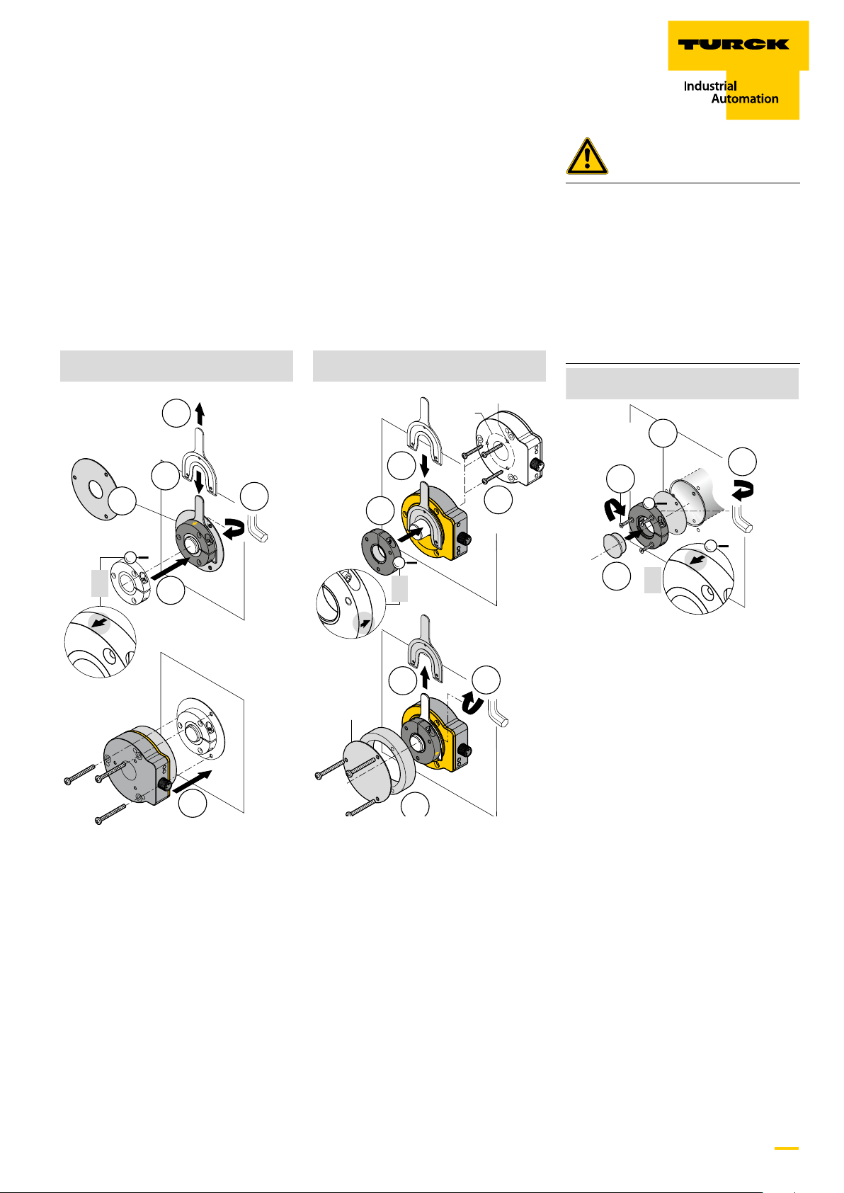
5 Assembly
An extensive range of assembly accessories
(see chapter 6) allows the easy adaptation to
many different shaft diameters. The shield
plates SP1-QR24 or SP2-QR24 or SP3-QR24
can optionally be used (depending on as-
sembly type) to increase the permissible dis-
tance between the positioning element and
the sensor. The illustrations below show the
5
2
1
SP2-QR24
!
3
4
2.5
simple design of the separate sensor and
resonator units, making them virtually re-
sistant to errors. The assembly can be done
as types A, B, and C.
M4 x 0.5 x 7.5
ø 42
2
3
1
1.4...1.5 Nm
!
WARNING
The positioning element is prone to
detaching from its mounting position if
assembled incorrectly.
Mortal danger due to possibility
of parts ejected at speed!
ӹ Assembly instructions must be complied
with
ӹ Ensure the correct attachment of the
positioning element, tightening torque:
M = 0.6…0.8 Nm
SP3-QR24
0.6...0.8 Nm
3
0.6...0.8 Nm
2
4
2.5
1
!
6
1 Optional shield plate SP2-QR24
can be inserted.
2 Attach assembly aid for optimised align-
ment of the positioning element.
3 Slide the positioning element onto the
rotatable shaft; ensure correct direction-
ality of the active surface (see inscription
on the side of the positioning element).
4 Affix the clamping bracket using a hex
key.
5 Remove the assembly aid.
6 Place the encoder with the aluminium ring
over the positioning element, and affix
with three screws, to create a closed, and
protected unit.
0.6...0.8 Nm
5
SP1-QR24
1 Slide the encoder on the back of the
shaft and affix.
2 Attach assembly aid for optimised align-
ment of the positioning element.
3 Slide the positioning element onto the
rotatable shaft; ensure correct direction-
ality of the active surface (see inscription
on the side of the positioning element).
4 Affix the clamping bracket using a hex
key.
5 Remove the assembly aid.
6 The protective aluminium unit and the
shield plate SP1-QR24 can optionally be
added.
4
2.5
Proceed as follows if the positioning element
is screwed onto a rotating machine part
and not onto a shaft:
1 Insert the blind plug RA8-QR24.
2 Affix the clamping bracket using a hex
key.
3 Insert the optional SP3-QR24 shield plate.
4 Affix the positioning element using
three sunken head screws, ensuring
the correct directionality of the active
surface (see inscription on the side of the
positioning element).
Mount the encoder depending on application requirement.
more@turck.com • www.turck.com • 2018/01
11
Page 12

QR24 Encoder with CANopen interface –
Configuration
6 Conguration
The wear-resistant encoder with CANopen interface is ideally suited for use in mobile machinery and industrial applications. Short latencies and cyclic, event-controlled communication are only two of the many advantages of the CANopen protocol, which is often used in
this area of application. A particular highlight is the software-controlled, bus-activated terminating resistor.
6.1 Objects 1000h – 1FFFh (communication proles)
6.1.1 Object 1000h: Device type
This object specifies the device type.
1000h VAR Device type Unsigned 32 RO M
Device prole number Encoder type
Byte 0 (LSB) Byte 1 Byte 2 Byte 3 (MSB)
96h* 01h* 01h (absolute encoder single-turn)
02h (absolute encoder multi-turn)
*196h = 406 decimal (encoder profile)
Example: 0001 0196h = profile DS406, absolute encoder single-turn
6.1.2 Object 1001h: Error Register
This register displays occurring device errors.
1001h VAR Error register Unsigned 8 RO M
Bit 0 = 0: no error
Bit 0 = 1: Error "No RLC coupling" (actuator not in range)
Bit 1...7: free
6.1.3 Object 1002h: Manufacturer status register
This register stores various error bits and the current status of the set limit values from object 6400h. The limit values are additionally
stored in object 6401h and object 6402h.
1002h VAR Manufacturer status register Unsigned 32 RO M
00h
Data content object 1002h :
Bit 0 =1: EEPROM error
Bit 1 =1: No RLC coupling (no resonator in range, no angle calculation possible)
Bit 2 =1: Minor RLC coupling (poss. increased non-linearity)
Bit 3…7: free (0)
Bit 8 =1: Operating range 1 out of range
Bit 9 =1: Operating range 1 underrun
Bit 10 =1: Operating range 1 underrun
Bit 11 =1: Operating range 2 out of range
Bit 12 =1: Operating range 2 underrun
Bit 13 =1: Operating range 2 underrun
12
Hans Turck GmbH & Co. KG • Tel. +49 208 4952-0 • Fax +49 208 4952-264
Page 13

QR24 Encoder with CANopen interface –
Communication profiles
6.1.4 Object 1005h: COB ID SYNC (COB ID for SYNC message)
The object defines the COB ID for the SYNC message. The object furthermore specifies, whether the device is a generator or receiver of SYNC
objects.
1005h VAR COB ID SYNC Unsigned 32 RW O
Data content:
Bit 0...10: 11 bit identifier; default ID = 80h
Bit 11...29: 0 (reserved for 29-bit identifier devices)
Bit 30: 0 (device does not generate SYNC messages)
Bit 31: 1 (device is receiver for SYNC messages)
6.1.5 Object 1008h: Manufacturer device name
Contains the manufacturer's device name.
1008h VAR Manufacturer device name Vis string RO O
Example:
RI360P0-QR24M0-CNX4-2H1150
6.1.6 Object 1009h: Manufacturer hardware version
Contains the manufacturer's version number.
1009h VAR Manufacturer hardware version Vis string RO O
Data content:
e.g. "HW-12718801 -" in ASCII code
Hardware version (127xxxxx) incl. change index (-, A, B…)
6.1.7 Object 100Ah: Manufacturer software version
Contains the manufacturer's software version number.
100Ah VAR Manufacturer software version Vis string RO O
Data content:
e.g. "SW-1.0.0.1" in ASCII code
more@turck.com • www.turck.com • 2018/01
13
Page 14

QR24 Encoder with CANopen interface –
Communication profiles
6.1.8 Object 1010h: Store parameters
Writing the command "save" initiates the storing of the parameters to the non-volatile memory (EEPROM).
1010h ARRAY Store parameters Unsigned 32 RW O
The following commands are stored with this command: 1005h, 1014h, 1800h (sub-index 1 and 3), 1802h (sub-index 1), 2000h, 2001h, 2005h,
6000h, 6001h, 6002h, 6003h, 6200h.
The command will only be executed when the string "save" is entered as the codeword in this sub-index to prevent accidental saves.
NOTE
The values stored in EEPROM (power ON values) will be irretrievably overwritten with this command!
A read access to the CANopen device provides information about its capability to store these values. (Data: 01h = storage possible)
Data content:
Write access:
Byte 0: 73h (ASCII code for "s")
Byte 1: 61h (ASCII code for "a")
Byte 2: 76h (ASCII code for "v")
Byte 3: 65h (ASCII code for "e")
s a v e = 0x65766173
6.1.9 Object 1011h: Restore default parameters
This command deletes the parameters in the working memory, and rep[laces them with default values (manufacturer values, resetting of
the encoder to values at time of delivery). A read access to the CANopen device provides information about its capability to restore these
values. (Data: 01h = reset possible)
1011h ARRAY Restore default parameters Unsigned 32 RW O
Multiple parameter groups are distinguished:
Sub-index 00h: contains the highest supported sub-index.
Sub-index 01h: Restore all parameters refers to all parameters than can be reset.
Sub-index 02h: Restore communication parameters refers to communication-relevant parameters (index from 1000h to 1FFFh).
Sub-index 03h: Restore application parameters refers to application-relevant parameters (index from 6000h to 9FFFh).
Example: Restore all parameters
Writing the command 0x64616F6C (=load) under sub-index 01h will reset all parameters in the encoder RAM to their default values.
A read access to the sub-index offers information of whether a reset to default values is possible.
Data content:
Write access: Read access:
Byte 0: 6Ch (ASCII code for "l") Bit 0 = 1: Device supports the loading of default values
Byte 1: 6Fh (ASCII code for "o")
Byte 2: 61h (ASCII code for "a") Bit 1...31 = 0: reserved
Byte 3: 64h (ASCII code for "d")
The default values become valid only after a "NMT reset“. After a "NMT reset" the command "Save parameter" (see object 1010h) must also be
executed if the default values are to be applied to EEPROM as well.
l o a d = 0x64616F6C
14
Hans Turck GmbH & Co. KG • Tel. +49 208 4952-0 • Fax +49 208 4952-264
Page 15

QR24 Encoder with CANopen interface –
Communication profiles
6.1.10 Object 1014h: COB D emergency
The object defines the COB ID for emergency messages The behaviour in case of an error is described in Object 1029h "Error behaviour".
1005h VAR COB ID EMCY Unsigned 32 RW O
Data content:
Bit 0...10: 11 bit identifier; default ID = 80h + node number
Bit 11...29: reserved for 29-bit identifier devices
Bit 30, 31: reserved
Emergency objects occur in error situations within a CAN network, and will be triggered depending on the type of event, and are then trans-
mitted via the bus with high priority.
NOTE
An emergency object will only be triggered once per event. No new object will be generated while the error persists. Once the
error has been remedied, a new emergency object with content 0000h ("Error reset" or "No error") will be generated and sent to
the bus.
Emergency messages for Turck CANopen sensors:
Code 0000h = No error
An "Emergency clear" message (code 0000h) will be transmitted during startup and after the "Boot up" message.
Code 5000h = Internal software error (device return to manufacturer)
An emergency message with the code 0x5000 with the following code class will be generated if the encoder has an internal hardware error:
0x5001: Hardware ROM check error: Device defective, please return to manufacturer!
Code 6100h = Internal software error
An emergency message with the code 0x6100 with the following code class will be generated if the encoder has an internal software error:
0x4000: only warning message, no program abort
0x4810: Write buffer overflow, TPDO message lost
0x4820: Write buffer overflow, TPDO message lost
0x4830: Write buffer overflow, SDO message lost
0x4840: Write buffer overflow, heartbeat message lost
0x8000: Grave error, abort required/reset
0x8010: MCO initialisation failed
0x8021: Not in the CAN receipt filter, NMT
0x8022: Not in the CAN receipt filter, PDO
0x8023: Not in the CAN receipt filter, SDO
0x8031: Initialisation of PDO parameters out of range
0x8032: Access to process image out of range
0x8041: Outside of TPDOs
0x8042: Outside of RPDOs
0x8043: No RPDO mapping found
more@turck.com • www.turck.com • 2018/01
15
Page 16

QR24 Encoder with CANopen interface –
Communication profiles
6.1.11 Object 1015h: Inhibit time emergency
The object denes the inhibit time for emergency messages. This object species the pre-congured inhibit time for the EMCY message.
The value is given in multiples of 100 µs. Select the value "0" to deactivate the inhibit time. (max. 6553 ms)
1015h VAR Inhibit time EMCY Unsigned 16 RW O
Default value: 0
Value range: 0, 10…65530
dec
(corresponds to 1 ms….6553 ms)
bin
NOTE
Only full millisecond values are stored. In-between values are rounded up.
6.1.12 Object 1017h: Producer heartbeat time
The producer heartbeat time defines the heartbeat cycle. The time must be set to "0" if this function is not needed. The function is activated
with a value of min. 1 ms. (1 ms ….32767 ms).
1017h VAR Producer heartbeat time Unsigned 16 RW O
Value range: 0…32767
Default value: 0
dec
(corresponds to 0 ms….32767 ms)
bin
NOTE
A heartbeat producer transmits the heartbeat message at the specified cycle times.
The content of the data bytes corresponds to the status of the CAN node:
Pre-operational: Data 7Fh
Operational: Data 05h
Stopped: Data 04h
6.1.13 Object 1018h: Identity object
This object reads the device ID.
1018h RECORD Device identication Identity (23h) RW O
Sub-index 0h : delivers the number of entries (4 entries)
Sub-index 1h: delivers the Turck vendor ID (0000009Ch)
Sub-Index 2h: delivers the product code (e.g. Turck QR24 CANopen)
Sub-Index 3h: delivers the SW revision number (e.g. 1.0.0.1), see table "3-Point notation"
Example: Version 1.0.0.1 = 10
Sub-index 4h: delivers the 8-digit serial number of the encoders
dec
_01
= 0Ah_01h = 0A01h
dec
16
Hans Turck GmbH & Co. KG • Tel. +49 208 4952-0 • Fax +49 208 4952-264
Page 17

QR24 Encoder with CANopen interface –
Communication profiles
6.1.14 Object 1029h: Error behaviour
In case of a grave error, the device reacts with the behaviour parametrised here.
1029h ARRAY Error behaviour Unsigned 8 RW O
Error classes:
0x1029, sub-index1 / communication error
(Default 1 = sensor does not change mode):
■ Bus OFF status
■ Heartbeat monitoring failed
0x1029, sub-index 2 / device profile-specific
(Default 1 = sensor does not change mode):
■ Error positioning element: No RLC coupling
0x1029, sub-index 3 / manufacturer-specific
(Default 1 = sensor does not change mode):
■ NV RAM / EEPROM error
■ System monitoring error
Value range (8 bit unsigned):
0 = sensor changes to pre-operational mode
1 = sensor does not change mode
2 = sensor changes to stopped mode
more@turck.com • www.turck.com • 2018/01
17
Page 18

QR24 Encoder with CANopen interface –
Communication profiles
6.1.15 Object 1800h: PDO1- Parameter (asynchronous)
PDO1: Metering value output "Position" in set time cycles
The object contains the parameter for the process data object PDO1. Via this service, the process data of the encoder is output asynchro-
nously, triggered by the internal cycle timer (prerequisite: the cycle timer was set via object 6200h).
1800h RECORD PDO1 parameter PDO COMMPAR (20h) RW M/O
Data content:
Sub-index 0h: Number of supported sub-indices.
Read only
Value range: 2...5
Sub-index 1h: COB ID and release
Bit 0…10: 11 bit identifier; default ID = 180h + node number
Bit 11...29: 0 (reserved for 29-bit identifier devices)
Bit 30: 0 = RTR permitted (cannot be modified)
Bit 31: 0 (PDO enabled), 1 (PDO disabled);
Default value = 0
Sub-index 2h: Transmission type = 255 dec. (see overview of transmission types)
(Transmission type = asynchronous)
(Overview see object1800h)
Sub-index 3h: Inhibit time, min. waiting time until PDO can be sent again. Default value = 0h (no inhibit time)
Value range: 10…65530
(corresponds to 1 ms….6553 ms)
bin
NOTE
Only full millisecond values are stored. In-between values are rounded up. Application of the values to the non-volatile memory
(EEPROM) via object 1010h. Default value: 0
Sub-index 4h: Assigned
Sub-index 5h: Event timer (Setting in object 6200h)
The value range for the timer is between 1…65535 x 1 ms = 1 ms ... 65535 ms.
Event timer = 0 -> no data output
Default value:100
dec
NOTE
The number of possible messages is limited by the bus speed. Minimum times for event timer are valid for the operation with one
PDO.
Baud rate Messages/ms Event timer (min)
1000 kBit/s 7,8 1 ms
500 kBit/s 3,9 1 ms
250 kBit/s 1,9 1 ms
125 kBit/s 0,97 2 ms
50 kBit/s 0,39 3 ms
20 kBit/s 0,15 7 ms
10 kBit/s 0,07 15 ms
18
Hans Turck GmbH & Co. KG • Tel. +49 208 4952-0 • Fax +49 208 4952-264
Page 19

QR24 Encoder with CANopen interface –
Communication profiles
6.1.16 Object 1801h: PDO2 parameters (synchronous, cyclic)
PDO2: Metering value output "Position" at SYNC request (80h)
The object contains the parameters for the process data object PDO 2. Via this service, the process data of the encoder are output synchro-
nously in the default setting, initiated by SYNC objects.
NOTE
The number of possible SYNC messages is limited by the bus speed.
1801h RECORD PDO2 parameters PDO COMMPAR (20h) RW M/O
Data content:
Sub-index 0h: Number of supported sub-indices.
Read only
Value range: 2...5
Sub-index 1h: COB ID and release
Bit 0…10: 11 bit identifier; default ID = 280h + node number
Bit 11...29: 0 (reserved for 29-bit identifier devices)
Bit 30: 0 = RTR permitted (cannot be modified)
Bit 31: 0 (PDO enabled), 1 (PDO disabled);
Default value = 0
Sub-index 2h: Transmission type = 1 dec (see overview of transmission types)
(Transmission type = synchronous, cyclic)
(Overview see object 1800h)
Sub-index 3h: Inhibit time, min. waiting time until PDO can be sent again. Default value = 0h (no inhibit time)
Value range: 10…65530
(corresponds to 1 ms….6553 ms)
bin
NOTE
Only full millisecond values are stored. In-between values are rounded up. Application of the values to the non-volatile memory
(EEPROM) via object 1010h. Default value: 0
Sub-index 4h: Assigned
Sub-index 5h: Event timer (Setting in object 6200h)
The value range for the timer is between 1…65535 x 1ms = 1ms...65535 ms.
The event timer is without function when transmission type 1h = synchronous, cyclic
Default value: 0
Operational: Data 05h
Stopped: Data 04h
NOTE
The number of possible messages is limited by the bus speed. Minimum times for event timer are valid for the operation with one
PDO. This is also valid for SNC times.
more@turck.com • www.turck.com • 2018/01
19
Page 20

QR24 Encoder with CANopen interface –
Communication profiles
Baud rate Messages/ms Event timer (min)
1000 kBit/s 7,8 1 ms
500 kBit/s 3,9 1 ms
250 kBit/s 1,9 1 ms
125 kBit/s 0,97 2 ms
50 kBit/s 0,39 3 ms
20 kBit/s 0,15 7 ms
10 kBit/s 0,07 15 ms
6.1.19 Overview transmission types
A value between 1...240 means that the PDO is sent synchronously or cyclic. The transmission type number means the number of SYNC
impulses required to send the PDOs. Transmission type 252 and 253 mean that the PDO is only sent on request via RTR.
Type 254 means that the event is triggered application-dependently, while number 255 is device profile-dependent.
Additionally, a time-controlled event timer can be implemented for the numbers 254/255. The value range for the timer is between
1 ms…65535 ms.
Code (dec.) Transmission type
cyclic acyclic synchronous asynchronous only RTR
0 X X
1-240 X X
241-251 reserved
252* X X
253* X X
254 X
255 X
* not supported
Meaning of the transmission type codes:
0: Synchronous = 0x00h, after SYNC, but only in case of value change after last SYNC
1-240: Cyclic-synchronous = 0xEF , send value after SYNC
241-251: Assigned
252: Synchronous with RTR = 0xFC
SYNCH leads to internal value storage, but value must be called via RTR;
253: Asynchronous with RTR = 0xFD
Value is updated and sent after RTR(request)
254 Manufacturer (asynchronous) = 0xFE
a) Value is updated and sent after a value change (if device timer = 0) or after completion of cycle time (device timer ≠ 0)
b) Value is updated and sent after RTR(request);
c) Cyclic RTR output with event- timer possible.
d) Combination with inhibit timer (inhibit time) possible
255: Asynchronous = 0xFFh, value is updated and sent after completion of cycle time (device timer ≠ 0)
20
Hans Turck GmbH & Co. KG • Tel. +49 208 4952-0 • Fax +49 208 4952-264
Page 21

QR24 Encoder with CANopen interface –
Variable PDO mapping
6.2 Variables PDO mapping
Variables mapping of the various objects means that the user can configure the content of the transmit PDOs application-independently.
There are two basic mapping options:
1. The properties of the PDOs can be configured individually via the object 1800h ff. (Transmission type, inhibit time, event
time)Time
2. Multiple PDOs up to max. 64 bit can be transmitted using one CAN telegram. These PDOs are listed in a mapping table. -> Objects
0x1A00ff, 0x01ff = mapping table
The max. data length of the CAN telegram is 65 bit (8 byte), therefore allowing the mapping of e.g. two application object entries with 32 bit
each, or four entries with 16 bit each in a mapping table (= objects 0x1A00ff, 0x01ff)
Two prerequisites must be met:
1. The overall size of the mapped objects within a PDO mapping table (objects 0x1A00ff) must not be surpass 64 bit.
2. All mapped objects in a PDO mapping table (objects 0x1A00ff) have the same transmission type, inhibit time, and event time.
Example: Mapping tables for TPDO1 and TPDO2
1800h mapping table TPDO 1 1801h mapping table TPDO 2
• Position value
• Position raw value
COB ID
1800h, 0x01
Transmission type
1800h, 0x02
Inhibit time
1800h, 0x03
Event time
1800h, 0x05
Mapping object1
1A00h,0x01
Mapping object 2
1A00h,0x02
xxxxxxxx COB ID
255 asynchronous Transmission type
0 Inhibit time
100 Event time
Position value
32 bit
Position raw value 32 bit Mapping object 2
• Position value
• Speed value
• Alarms
1801h, 0x01
1801h, 0x02
1801h, 0x03
1801h, 0x05
Mapping object1
1A01h,0x01
1A01h,0x02
xxxxxxxx
254 synchronous
0
0
Position value
32 bit
Speed value
16 bit
Mapping object 3
1A00h,0x03
Mapping object 4
1A00h,0x04
more@turck.com • www.turck.com • 2018/01
No entry, as 64 bits assigned Mapping object 3
No entry, as 64 bits assigned Mapping object 4
1A01h,0x03
1A01h,0x04
Alarms
16 bit
No entry, as 64 bits assigned
21
Page 22

QR24 Encoder with CANopen interface –
Variable PDO mapping
Sample entry in the mapping table:
The mapped PDO consists of 3 application object entries with varying lengths:
Application object 2 occupies byte 1 (08h) in the transmission PDO. Application object 3 with a length of 16 bit (10h = 2 byte) follows, and
then comes application object 1 with 1 byte length. Overall, 32 bit are assigned in this PDO.
6.2.1 Object 1A00h: PDO1 mapped object
Up to four application objects (position, speed, ...) can be transmitted in one PDO. The max. data length is 64 bit. The PDO mapping is
possible only with the objects 6000h – 6FFFh.
1A00h RECORD PDO1 mapping parameter PDO MAPPING (21h) RW M/O
Data content:
Sub-index 0h: Number of supported sub-indices.
Read only
Value range: 1...4
Sub-index 1h: 1_mapped_object (default: 0x60040020, position value)
Example:
Mapping TPDO1 position value
Object: 6004h
Sub-index of the object: 00h
Data length: 20h (32 bit)
The value 0x60040020 is entered in the object 0x1A00, 0x01.
0x1010, 0x01: Save parameters, data: 0x6576617 (PWR on reset required)
Sub-index 2h: 2_mapped_object (default: no entry)
Sub-index 3h: 3_mapped_object (default: no entry)
Sub-index 4h: 4_mapped_object (default: no entry)
22
Hans Turck GmbH & Co. KG • Tel. +49 208 4952-0 • Fax +49 208 4952-264
Page 23

QR24 Encoder with CANopen interface –
Variable PDO mapping
6.2.2 Object 1A01h: PDO2 mapped object
Up to four application objects (position, speed, ...) can be transmitted in one PDO. The max. data length is 64 bit. The PDO mapping is possible
only with the objects 6000h – 6FFFh.
1A01h RECORD PDO2 mapping parameter PDO MAPPING (21h) RW M/O
Data content:
Sub-index 0h: Number of supported sub-indices.
Read only
Value range: 1...4
Sub-index 1h: 1_mapped_object (default: 0x60040020, position value)
Sub-index 2h: 2_mapped_object (default: no entry)
Sub-index 3h: 3_mapped_object (default: no entry)
Sub-index 4h: 4_mapped_object (default: no entry)
more@turck.com • www.turck.com • 2018/01
23
Page 24

QR24 Encoder with CANopen interface –
Variable PDO mapping
6.2.5 Example: Create mapping for PDO3 (speed)
Up to four application objects (position, speed, ...) can be transmitted in one PDO. The max. data length is 64 bit.
Example:
A ) Configure the communication parameters via object 1802h
The communication parameters of the encoder are configured via object 1802h (communication parameter). These include: COB ID, trans-
mission type, inhibit time, event time
B ) Current metering values are stored in object 6030h sub-index 01h only.
C ) The mapping is stored in object 1A02h sub-index 01h.
24
Hans Turck GmbH & Co. KG • Tel. +49 208 4952-0 • Fax +49 208 4952-264
Page 25

QR24 Encoder with CANopen interface –
Variable PDO mapping
The mapping consists of the following:
Mapping TPDO3 Speed
Object: 6030h
Sub-index of the object: 01h
Data length: 10h (16 bit)
Mapping 0x60300110
The value 0x60300110 is entered in the object 0x1A02, 0x01.
0x1010, 0x01: Save parameters, data: 0x65766173 (PWR on reset required)
6.2.6 Default setting for transmit PDO settings
The CANopen encoder supports variable mapping on all transmit PDOs.
PDO TPDO1 TPDO2 TPDO3 TPDO4
Mapping object 1A00h 1A01h 1A02h 1A03h
Transmission type
Object:
0x1800 ff, 0x02
Object of the metering
value
Sub-index 00h 00h 00h 01h
Data length 20h (32 bit) 20h (32 bit) 20h (32 bit) 10h (16 bit)
Mapping 0x60040020 0x60040020 0x60040020 0x60300110
6.2.7 PDO mapping in accordance with CiA (from CANopen version 4)
The default assignment of the process data objects (default mapping) will generally satisfy requirements. For special use cases, the assign-
ment can be changed: Many Turck CANopen devices support variable mapping, which allows the free assignment of application objects
(input and output data) to PDOs. This will require a configuration of the mapping tables: Only the following procedure is permissible as of
CANopen version 4, which must be complied with to the letter:
255h
"Position" in set time cy-
cles
6004h 6004h 6004h 6030h
001h
"Position" at SYNCH
request (80h)
254h
"Position" at value
change
255h
"Speed" in set time cycles
1. 0x1800ff, sub-index 1, COB ID, set bit 31 to "1" (lock PDO)
Data: 0x4000 019B -> 0xC000 019B (example)
2. 0x1A00ff, sub-index 0, set number of mapping entries to"0"
Data: 0x01 -> 0x00 (example: one entry to zero entries)
3. 0x1A00ff, change sub-index 1(…8)
Data: 0x6004 0020 -> 0x600C 0020 (example)
4. 0x1A00ff, sub-index 0, set number of mapping entries to "1, 2, 3…".
Data: 0x00 -> 0x01 (example: one entry)
5. 0x1800ff, sub-index 1, COB ID, set bit 31 to "0" (unlock PDO)
Data: 0xC000 019B -> 0x4000 019B (example)
more@turck.com • www.turck.com • 2018/01
25
Page 26

QR24 Encoder with CANopen interface –
Manufacturer specifications
6.3 Objects 2000h – 2FFFh (manufacturer specications)
6.3.1 Object 2100h: Baud rate
The Baud rate without LSS service is set via this object.
2100h VAR Baud rate Unsigned16 RW M
NOTE
A password is necessary to change the object. Service pass code object 0x2900, 0x01 (Unsigned32). The password is 12345 (dec)
resp. 0x3039.
Takes effect after next reset/power ON reset
Object 0x2100 sub-index: 0x00 Data: 1000 = 1000 kbps (unsigned 16)
Data: 500 = 500 kbps (unsigned 16)
Data: 250 = 250 kbps (unsigned 16)
Data: 125 = 125 kbps (unsigned 16)
Data: 50 = 50 kbps (unsigned 16)
Data: 20 = 20 kbps (unsigned 16)
Data: 10 = 10 kbps (unsigned 16)
Default 125 kbps
6.3.2 Object 2101h: Node number
The node number can be changed using software via this object. The default value is 0x03h. The device will boot with a changed node ad-
dress after next activation or "Reset node" if the value is set between 1...127.
2101h VAR Node number Unsigned8 RW M
NOTE
A password is necessary to change the object. Service pass code object 0x2900, 0x01 (Unsigned32). The password is 12345 (dec)
resp. 0x3039.
Value range: 1…127 or 1…7Fh
Default settings: 03h
NOTE
Node number 0 is reserved and must not be used by any other node.
A new node number is applied only after the next boot-up (Reset/Power ON) of the encoder. All other settings in the object table remain
unchanged.
26
Hans Turck GmbH & Co. KG • Tel. +49 208 4952-0 • Fax +49 208 4952-264
Page 27

QR24 Encoder with CANopen interface –
Manufacturer specifications
6.3.3 CANbus termination
This object enables/disables the bus termination. An integrated 120 W terminating resistor will be enabled/disabled accordingly.
2102h VAR CAN bus termination Unsigned8 RW M
The change takes effect when "Save all bus parameters" (0x2105) is executed
Access: R/W
Value range: 8 bit unsigned
1=termination on
0=termination off
6.3.4 Object 2104h: NMT autostart
The start-up mode of the encoder is specified via this object.
2104h VAR NMT autostart Unsigned8 RW M
Object 0x2104 sub-index: 0x00 Data: 0 = Pre-operational
Data: 1 = Operational
6.3.5 Object 2105h: PDO trigger threshold
Up to four application objects (position, speed,...) can be transmitter in one PDO. The max. data length is 64 bit.
2105h VAR PDO trigger threshold Unsigned8 RW M
Setting the PDO trigger threshold:
Configure the trigger threshold for the angle change as follows:
Object 0x2105 sub-index: 0x00 Data: 0…255 (unsigned 8)
Default = 20
Example: For the PDO to be transmitted automatically, the position value must change by at least 10 if the value is set to 10.
NOTE
The PDO function "Transmit when angle changes" (transmission type = 254 dec.) must be enabled. Configure the desired PDOs as
follows: Object: 0x1800ff , sub-index:0x02, Data: 0xFE(Manufacturer).
6.3.6 Object 2106h: Filter conguration
Two filter types can be selected for filtering metering values. A configurable low pass filter and a configurable dynamic filter.
2106h VAR Filter conguration Unsigned8 RW M
At standstill (motion detection), the filter is operated with a low threshold frequency (high group delay), allowing for minimal signal noise
at high resolution. A low pass filter (moving average) is a first order type. The dynamic digital filter is status and speed-dependent. The filter
constant can be set in object 2106h, sub-index 0x02. A switchover to a high threshold frequency occurs (low group delay), when the position-
ing element is moved.
more@turck.com • www.turck.com • 2018/01
27
Page 28

QR24 Encoder with CANopen interface –
Manufacturer specifications
The filters can be selected as follows:
Object: 0x2106 sub-index: 0x01 Data: 0 = Filter OFF
1 = Low pass filter ON
2 = Dynamic IIR filter ON
Configuring the filter constant. The setting applies for both filter types:
Object: 0x2106 sub-index: 0x02 Data: 1…255 (Default =20)
NOTE
It will take several seconds for the current metering value to level out if the values selected for the filter constant are very high
(higher than 50).
6.3.7 Object 2110h: Customer memory
The start-up mode of the encoder is specified via this object.
2110h VAR Customer memory Unsigned32 RW M
0x2110, 0x01…0x04 Customer memory range
- Four number values can be stored here in the range unsigned 32.
- The stored data is informal and have no impact on the function of the encoder.
- e.g. Installation date: 2014 = 11111011110b
6.3.8 Object 2200h: Sensor Amplitude (Manufacturer)
The access on the actually sensor amplitude (resonant circuit coupling) is possible via this object.
2200h VAR Sensor Amplitude Unsigned16 RO M
0x2200, 0x00 - The value should be min. 1200dec.
- Can be mapped via PDO.
- Not available in the EDS file.
NOTE
A password is necessary to change the object. Service-pass code object 0x2900, 0x01 (Unsigned32). The password is 12345 (dec)
resp. 0x3039.
6.3.9 Objekt 2201h: Target Frequence Deviation (Manufacturer)
The access on the actually frequency deviation of the resonant circuit is possible via this object.
2201h VAR Target Frequence Deviation Integer16 RO M
0x2201, 0x00 - The value of ±9375dec should not be exceeded/underrun
- Can be mapped via PDO.
- Not available in the EDS file.
NOTE
A password is necessary to change the object. Service-pass code object 0x2900, 0x01 (Unsigned32). The password is 12345 (dec)
resp. 0x3039.
28
Hans Turck GmbH & Co. KG • Tel. +49 208 4952-0 • Fax +49 208 4952-264
Page 29

QR24 Encoder with CANopen interface –
Default device parameters
6.4 Objects 6000h – 6FFFh (default device parameters)
6.4.1 Object 6000h: Operating parameters
This object activates: code sequence reversal, diagnostics request, scaling function.
6000h VAR Operating parameters Unsigned16 RW M
Data content:
Bit 0: Code sequence; 0 = Ascending when rotation is clockwise (cw)
1 = Ascending when rotation is counter-clockwise (ccw)
Default: Bit = 0
Bit 1: free (0)
Bit 2: Scaling function; (scaling configuration via object 6001,6002)
0 = disable (sensor outputs raw data)
1 = enable (see object 6001h, 6002h)
Default: Bit = 1
NOTE
The scaling function is available only for Device_Type 0 and 1. See: Objects 2900h 0x03 and 2900h, 0x04.
Bit 3...12: free (0)
Bit 13: Speed format;
0 = Revolutions/minute (RPM)
Default: Bit = 0
Bit 14…15: free (0)
6.4.2 Object 6001h: MUR (Measuring Units per Revolution)
This parameter sets the desired resolution per revolution.
6001h VAR Measuring units per revolution Unsigned32 RW M
The encoder calculates the relevant scaling factor internally. Prerequisite: Scaling function bit 2 of object 6000h = 1
Value range: 1 … max. physical resolution (full range)
RI360P0-QR24M0-CNX4-2H1150: 327680 = full range
Default settings: 36000
NOTE
The max. physical resolution is a factory setting in object 6501h (read only). In object 6000h bit 2: Set scaling function to enable (1).
more@turck.com • www.turck.com • 2018/01
29
Page 30

QR24 Encoder with CANopen interface –
Default device parameters
6.4.3 Object 6001h: TMR (Total Measuring Range)
This object species the measuring range.
6002h VAR Total measuring range Unsigned32 RW M
Value range: 1…max. physical resolution (full range)
RI360P0-QR24M0-CNX4-2H1150: 327680 = full range
Default settings: 36000
TMR = MUR / n, n=1, 2 ,3… applies if the encoder us used in single-turn mode.
MUR: Object 6001h
TMR: Object 6002h
At a physical zero crossover, a skip will occur in the source code (in single-turn mode after every rotation).
NOTE
In object 6000h bit 2: Set scaling function to enable (1).
Example 1:
Setting: 6001h: MUR= 3600 (value range: 1 … max. phys. resolution)
6002h: TMR= 360 (value range: TMR = MUR/n, n=1, 2 ,3…)
Output: One revolution is divided into 10 × 0…360
Example 2:
Setting: 6001h: MUR= 3600
6002h: TMR= 3600
Output: One revolution is divided into 0…3600
Example 3 skip in the source code:
Setting: 6001h: MUR= 3600
6002h: TMR= 3000
Output: One revolution is divided into 0…3000 and 0…600
NOTE
The max. physical resolution is a factory setting in object 6501h (read only). In object 6000h bit 2: Set scaling function to enable (1).
30
Hans Turck GmbH & Co. KG • Tel. +49 208 4952-0 • Fax +49 208 4952-264
Page 31

QR24 Encoder with CANopen interface –
Default device parameters
6.4.4 Object 6003h: Preset value
The position value of the encoder is configured to this preset value. This allows e.g. an endpoint alignment of the encoder with the machine
endpoint.
6003h VAR Preset value Unsigned32 RW O/M
Value range: Ri360P0-QR24M0-CNX4-2H1150: 1…327680
Default settings: 0
During the input of the preset value, the device automatically checks whether the point is within the enabled scaling or the total measuring
range, otherwise the input will be rejected.
Example 1:
Currently read measuring value: 33
Preset value: Write the value 0 to object 6003h.
Result offset: The measuring value changes from 33 to 0. The endpoint is moved by -33.
Example 2:
Currently read measuring value: 33
Preset value: Write the value 50 to object 6003h.
Result offset: The measuring value changes from 33 to 50. The endpoint is moved by +17.
The offset value is calculated and stored additionally in object 0x6509, 0x00.
Offset value = preset value - position measuring value
6.4.5 Object 6004h: Position value
The encoder outputs the current position value (poss. after calculation with scaling factor).
6004h VAR Position value Unsigned32 RO M
Data:
Value range: 0... max. physical resolution
Default: actual position
more@turck.com • www.turck.com • 2018/01
31
Page 32

QR24 Encoder with CANopen interface –
Default device parameters
6.4.6 Object 600Ch: Position raw value
The encoder outputs the current position value in max. physical resolution (no scaling).
600Ch VAR Position raw value Unsigned32 RO O/M
Value range:
RI360P0-QR24M0-CNX4-2H1150: 0…327680 (full range)
6.4.7 Object 6030h: Speed value
The encoder outputs the currently calculated speed in rpm.
6030h VAR Speed value Signed16 RO O
This value is output in a read access with object 6030h as a signed 16 bit value.
Positive value = clockwise rotation
Negative value = counter-clockwise rotation
Value range: 0…max. speed 1500 rpm.
Example: 500 rpm counter-clockwise -> - 500
A warning message is issued for speeds higher than 1500 rpm, and the warning bit "Speed range" bit 6 in object Warnings 6505h is set. Rel-
evant mapping will allow the output of the speed via PDO.
dec
NOTE
Prerequisite here is that bit 13 (Speed format) in object 6000h is set to 0.
6.4.8 Object 6200h: Cycle timer
Defines the cycle time in which the current position is output via PDO1 (see object 1800h). The timer-controlled output is enables as soon
as a cycle time >0 is entered. Applies to PDO1 only.
6200h VAR Cyclic timer Unsigned16 RW M/O
Note: This object only remains for reasons of compatibility with older profile versions. In the current transmit PDO, the event timer sub-index
(05h) should be used instead.
Value range: 0…FFFFh (65535
Default value: 100
dec
) provides the cycle time in milliseconds.
dec
NOTE
No measuring value output occurs if cycle time = 0.
32
Hans Turck GmbH & Co. KG • Tel. +49 208 4952-0 • Fax +49 208 4952-264
Page 33

QR24 Encoder with CANopen interface –
Default device parameters
6.4.9 Object 6400h: Work area state register
This object contains the current status of the encoder position in relation to the programmed limits. Depending on position of the two
endpoints, flags are set or reset. Where the measuring values are within the work area, bits 0...7 will have the value 0.
6400h VAR Area state register Unsigned8 RO O
Object 0x6400, 0x01, work area state register channel 1 (Unsigned8)
Bit 0 =1: Outside of work_area_1
Bit 1 =1: Greater than high_limit_1
Bit 2 =1: Less than low_limit_1
Bit 3…7: free (0)
Data: 05h = Position value < low limit
Data: 00h = Position value within limit
Data: 03h = Position value > high limit
Object 0x6400, 0x02, work area state register channel 2 (Unsigned8)
Bit 0 =1: Outside of work_area_2
Bit 1 =1: Greater than high_limit_2
Bit 2 =1: Less than low_limit_2
Bit 3…7: free (0)
Data: 05h = Position value < low limit
Data: 00h = Position value within limit
Data: 03h = Position value > high limit
NOTE
The two end value objects 6401h and 6402h must be checked to ensure the correct activation of the output signals. These limit
values are additionally stored in the object 0x1002 "Manufacturer status register", and can therefore also be mapped as PDO.
6.4.10 Objects 6401h and 6402h: Working area limits
These two parameters set the working area. The status can be reported via flag bytes within and outside of this area (object 6400 "Working
area state"). These area markers can also be used as software end switches.
6401h/02h VAR Working area limits H/L Integer32 RW O
Object 6401h: Working area LOW limit 2 values
Object 6402h: Working area HIGH limit 2 values
Value ranges:
Ri360P0-QR24M0-CNX4-2H1150: 0… 327680 dec. (full range)
more@turck.com • www.turck.com • 2018/01
33
Page 34

QR24 Encoder with CANopen interface –
Default device parameters
Default setting:
Working area LOW limit: 0
Working area HIGH limit: 0
Example 1:
Set measuring range to 3600 using 6001h and 6002h.
Limit values range 1: 0…3600, range 2: 0…3600, i.e. all measuring values 0…3600 must be in the range.
0x6400, 0x00 = 0x01 -> 1 channel
0x6400, 0x01 = 0x09 -> 0000 1001-> values in range 1 and range 2 (see 6400h)
0x6401,0x00 = 0x02
0x6401,0x01 = 0 (low limit 1)
0x6401,0x02 = 0 (low limit 2)
0x6402,0x00 = 0x02
0x6402,0x01 = 3600 (high limit 1)
0x6402,0x02 = 3600 (high limit 2)
Example 2:
Limit values range 1: 900…3600 (90°…360°), range 2: 1800…3600 (180°…360°)
Current measuring value: 450 (45°)
dec
dec
0x6400, 0x00 = 0x01 -> 1 channel
0x6400, 0x01 = 0x24 -> 0100 0100 -> values in range 1 and range 2 < low limit (see object 6400h)
0x6401,0x00 = 0x02
0x6401,0x01 = 900 (low limit 1)
0x6401,0x02 = 1800 (low limit 2)
0x6402,0x00 = 0x02
0x6402,0x01 = 3600 (high limit 1)
0x6402,0x02 = 3600 (high limit 2)
6.4.11 Object 6500h: Operating status read only
This is where the basic settings can be read from object 6000h.
6500h VAR Operating status Unsigned16 ro M
34
Hans Turck GmbH & Co. KG • Tel. +49 208 4952-0 • Fax +49 208 4952-264
Page 35

QR24 Encoder with CANopen interface –
Default device parameters
6.4.12 Object 6501h: Single-turn resolution (read only)
This is where the basic settings can be read from object 6000h. Resolution value (max. phys. resolution) is stored in the encoder, and can
only be read.
6501h VAR Single-turn resolution Unsigned32 RO M
Resolution value:
RI360P0-QR24M0-CNX4-2H1150: 327680
Item No.: 1590914
6.4.13 Object 6502h: Number of distinguishable revolutions (read only)
Number of possible multi-turn revolutions
6502h VAR Number of distinguishable revolutions Unsigned16 RO M
Number of revolutions:
RI360P0-QR24M0-CNX4-2H1150: 1
Item No.: 1590914
6.4.14 Object 6503h: Alarms (read only)
The object 6503h offers more error message options in addition to the errors reported in emergency messages. The relevant error bit is set to
1 until the error has been remedied.
6503h VAR Alarms Unsigned16 RO M/O
Data content:
Bit 0…14: free
Bit 15: 1 = no RLC coupling, no position metering possible
In the event of an alarm, an emergency message (ID = 80h + node number) with error code 1000h (generic error) is sent simultaneously.
more@turck.com • www.turck.com • 2018/01
35
Page 36

QR24 Encoder with CANopen interface –
Default device parameters
6.4.15 Object 6504h: Supported alarms (read only)
This object offers information about which alarm messages are supported by the encoder (see object 6503h).
6504h VAR Supported alarms Unsigned16 RO M/O
Data content:
Bit 0…14: free
Bit 15: 1 = Check for "No RLC coupling" is supported
6.4.16 Object 6505h: Warnings (read only)
Warning messages show that tolerances of internal encoder parameters have been breached. When a warning message is displayed, the
measuring value can still be valid (other than with alarm or emergency messages). The relevant warning bit is set to 1 until the tolerance
breach has been remedied.
6505h VAR Warnings Unsigned16 RO M/O
Data content:
Bit 0…5: free
Bit 6: 1 = Overrun of permissible speed (speed range);
Bit 7…14: free
Bit 15: 1 = Amplitude (RLC coupling) weak, but measuring value OK
6.4.17 Object 6506h: Supported warnings (read only)
This object offers information about which warning messages are supported by the encoder (see object 6505h).
6506h VAR Supported warnings Unsigned16 RO M/O
Data content:
Bit 0…5: free
Bit 6: 1= Warning message "Overspeed" is supported.
Bit 7…14: free
Bit 15: 1= Warning message "RLC coupling weak" is supported.
36
Hans Turck GmbH & Co. KG • Tel. +49 208 4952-0 • Fax +49 208 4952-264
Page 37

QR24 Encoder with CANopen interface –
Default device parameters
6.4.18 Object 6507h: Prole and software version (read only)
The first 16 bit contain the version number of the encoder profile applied. The second 16 bit contain the number of the software version
implemented in the encoder.
6507h VAR Prole and software version Unsigned32 RO M/O
Software version
Example: 1.2.3.4
Profile version
The version of the CiA DS-406 profile is stored
Data content:
Software version DS406 version
Byte 3 Byte 2 Byte 1 Byte 0
31
24
2
... 2
Example: CiA DS406 version: 3.2 = 3
Software version: 1.0.0.1= 10
dec
_01
23
2
... 2
_2
dec
dec
= 0Ah_01h
dec
16
= 03h_02h
15
8
2
... 2
27 ... 2
Byte 3 Byte 2 Byte 1 Byte 0
0Ah 01h 03h 02h
0
more@turck.com • www.turck.com • 2018/01
37
Page 38

QR24 Encoder with CANopen interface –
Default device parameters
6.4.19 Object 6509h: Oset value (read only)
A preset value entered via object 6003h is converted internally into a relevant offset value. Object 6509h displays the calculated offset value.
6509h VAR Oset value Signed32 RO M/O
The offset value is calculated as follows: Offset = preset - position
6.4.20 Object 650Ah: Module identication (read only)
This object contains various manufacturer-specific data. These include the manufacturer-specific offset value, and the min. and max. position values. All values are stated in the number of steps following the basic resolution of the encoder.
650Ah VAR Module identication Signed32 RO M/O
Data content:
0x650A, 0x00 Number of entries
0x650A, 0x01 Manufacturer offset value
0x650A, 0x02 Manufacturer minimum position value
0x650A, 0x02 Manufacturer maximum position value
6.4.21 Object 650Bh: Serial number (Read only)
This object contains the serial number of the encoder.
650Bh VAR Serial number Unsigned32 RO M
NOTE
All other objects not listed here are for additional information purposes only, and can be found in the encoder prole DS406 3.1.
6.5 LSS services DS 305 V2.0
CiA DSP 305 CANopen layer setting service and protocol (LSS) were created to allow the reading and modification of the following param-
eters via the network:
■ Node address
■ Baud rate
■ LSS address
These capabilities enhance the plug & play compatibility of the device, and significantly simplify the configuration options. The LSS master is
in charge of the configuration of these parameters for one or more slaves in the network.
LSS services
LSS hardware requirements (LSS address)
All LSS slaves must have a valid object entry for the identity object [1018h] in the object register to allow a selective node configuration. This
object consists of the following sub-indices:
■ Vendor ID (numerical number)
■ Product code (numerical number)
■ Revision number (major and minor revision as numerical number)
■ Serial number (numerical number)
■ LSS master CAN ID 2021
■ LSS slave CAN ID 2020
38
Hans Turck GmbH & Co. KG • Tel. +49 208 4952-0 • Fax +49 208 4952-264
Page 39

QR24 Encoder with CANopen interface –
Network management
6.6 Network management
The encoder supports the simplified network management (minimum boot-up) defined in the profile for minimum capability devices.
The following status diagram in accordance with DS 301 shows the various node states and relevant network commands (controlled by the
network master via NMT services):
Power-on
Reset
Initialisation
automatically
change to pre-
operational
Pre-operational
node
reset commu-
nication
change to pre-
operational
change to
operational
change to pre-
operational
change to prepared
Prepared
Operational
change to prepared
change to
operational
Initialisation: This is the initial state of the device after connection to the power supply following a reset or power-up. The node automati-
cally cycles to the status "pre-operational", once the reset/initialisation routines are completed. The LEDs show the current device status.
Pre-operational: The CAN node can now be addressed via SDO messages or with NMT commands under the default identifier. The pro-
gramming of the encoder and communication parameters is executed.
Operational: The node is enabled. Process values are output via the PDOs. All NMT commands can be evaluated.
Prepared or stopped: In this state, the node is no longer enabled, i.e. no SDO or PDO communication is possible. The node can be cycled to
the status "Operational" or "Pre-operational" via NMT commands.
NOTE
The Encoder-LED might be dierent from the selected node-condition.
more@turck.com • www.turck.com • 2018/01
39
Page 40

QR24 Encoder with CANopen interface –
Assembly accessories
7 Accessory
7.1 Assembly accessories
A wide range of accessories is available for the assembly of the sensor.
7.2 Standard assembly accessories
A matching assembly set is available for each device type (see type key, chapter 2.2). The assembly sets contain the aluminium ring M1-QR24
and a shield plate (SP1-QR24 or SP2-QR24, or SP3-QR24).
Dimension drawing Ty pe Description
not shown RKC5701-5M
RSC5701-5M
RA1-QR24
RA2-QR24
ø 28
ø 24
ø 20
2
9.9
RA3-QR24
RA4-QR24
RA5-QR24
RA6-QR24
RA7-QR24
MT-QR24 Mounting aid for optimised
ø 28
ø 24
2
9.9
RA8-QR24 Blind plug for the assembly of
Adapter line for the connection
of the sensor to CANopen
(female)
Adapter line for the connection
of the sensor to CANopen
(male)
Adapter sleeve for connection on
shafts with Ø 20 mm
Adapter sleeve for connection on
shafts with Ø 14 mm
Adapter sleeve for connection on
shafts with Ø 12 mm
Adapter sleeve for connection on
shafts with Ø 10 mm
Adapter sleeve for connection on
shafts with Ø 6 mm
Adapter sleeve for connection on
shafts with Ø 3/8"
Adapter sleeve for connection on
shafts with Ø 1/4"
alignment of positioning element
the positioning element
Set Description
M2-QR24 M1-QR24 +
SP1-QR24
Shield plate
Ø 74 mm, aluminium
ø 4.5
ø 74
ø 65
M3-QR24 M1-QR24 +
SP2-QR24
Shield plate
Ø 74 mm, with borehole for
shaft feed through,
aluminium
ø 4.5
ø 74
ø 22
ø 65
M4-QR24 M1-QR24 +
SP3-QR24
Shield plate
Ø 52 mm, aluminium
120°
2
120°
2
40
ø 3.2
ø 52
ø 42
120°
2
Hans Turck GmbH & Co. KG • Tel. +49 208 4952-0 • Fax +49 208 4952-264
Page 41

QR24 Encoder with CANopen interface –
ø 20
Positioning element accessories
7.3 Positioning element
A variety of positioning elements can be im-
plemented.
The positioning elements are connected
to the moving parts of the machine, but
are themselves capable of free movement
(without any mechanical connection to the
sensor) across the active surface of the sen-
sor.
Dimension drawing Type Description
ø 3.2
ø 52
ø 42
ø 3.2
ø 52
ø 42
ø 3.2
ø 52
ø 42
ø 3.2
ø 52
ø 42
ø 14
ø 12
ø 10
P1-Ri-QR24 Positioning element for connec-
10
P2-Ri-QR24 Positioning element for connec-
10
P3-Ri-QR24 Positioning element for connec-
10
P4-Ri-QR24 Positioning element for connec-
10
tion on shafts with Ø 20 mm
tion on shafts with Ø 14 mm
tion on shafts with Ø 12 mm
tion on shafts with Ø 10 mm
ø 3.2
ø 52
ø 42
ø 3.2
ø 52
ø 42
ø 3.2
ø 52
ø 42
ø 3.2
ø 52
ø 42
ø 6
ø 3/8“
ø 1/4“
P5-Ri-QR24 Positioning element for connec-
tion on shafts with Ø 6 mm
10
P6-Ri-QR24 Positioning element for connec-
tion on shafts with Ø 3/8"
10
P7-Ri-QR24 Positioning element for connec-
tion on shafts with Ø 1/4"
10
P8-Ri-QR24 Positioning element with blind
plug
10
more@turck.com • www.turck.com • 2018/01
41
Page 42

QR24 Encoder with CANopen interface –
31
Technical data
8 Technical data
LED
M12 x 1
ø 78 ø 22 ø 4.3 ø 65
24
42.3
81
10
Connection diagram
CAN IN CAN OUT
2
5
4
Measuring range specications
Measuring range 0…360°
Single-turn operation
System
Resolution
Repeatability
Linearity deviation
Temperature drift
Ambient temperature
16 bit
0.01 %
≤ 0.05 % full scale
≤ ± 0.003 %/K
-25…+85 °C
Electrical data
Operating voltage
Residual ripple
Rated insulation voltage
Reverse polarity protection
Output function
Process data area
Sampling rate
Current consumption
15…30 VDC
≤ 10 % U
ss
≤ 0.5 kV
yes (voltage supply)
5-core, CANopen
parametrisable
800 Hz … 1 kHz
< 50 mA
Design
Dimensions
Housing material
Connection
Vibration resistance
Oscillation resistance
Shock resistance
Continuous shock resistance
Protection type
81 × 78 × 24 mm
metal/plastic, ZnAlCu1/PBT-GF30-V0
2 × male connectors, M12 x 1, 5-pin CAN IN and CAN OUT
EN 60068-2-6, 55 Hz
20 g; 10...3000 Hz; 50 cycles; 3 axes
EN 60068-2-27, 30 g
40 g; 6 ms ½ sinus; 4000x each; 3 axes
IP67 / IP69K
LED displays
Operating voltage display
Signal status
Operating status
Error indication
LED green
LED, yellow, flashing yellow
LED green, flashing green
LED red, flashing red
Miscellaneous
Included in the scope of delivery Assembly aid MT-QR24
VZ 3 screw plug
2
1
5
3
4
42
Hans Turck GmbH & Co. KG • Tel. +49 208 4952-0 • Fax +49 208 4952-264
Page 43

QR24 Encoder with CANopen interface –
Service
9 Service
The fault-free condition of the connections and cables must be verified periodically. The device itself is maintenance-free; clean with dry cloth
where necessary.
10 Repairs
This device is not intended for repair by the user. Please take the device offline if it is defective. Please note our returns conditions for any
returns to Turck.
11 Device returns
Please note that we can only accept the return of devices accompanied by a decontamination declaration, should it become necessary to
return a device. The declaration form is available for download at http://www.turck.de/static/media/downloads/Dekontamination_de.pdf,
must be filled out completely, and must be attached to the exterior of the packaging in a transport-safe and weather-proof sleeve.
12 Disposal
This device is intended for integration in large industrial plants and tool assemblies. The devices must be disposed of correctly and cannot be
disposed of in regular household waste.
more@turck.com • www.turck.com • 2018/01
43
Page 44

Your
Automation Partner
Hans Turck GmbH & Co. KG
Witzlebenstr. 7
45472 Mülheim an der Ruhr
Germany
Tel. +49 (0) 208 4952-0
Fax +49 (0) 208 4952-264
Email more@turck.com
Internet www.turck.com
Worldwide!
D102186 2018/01
*D102186*
Errors and changes reserved
 Loading...