

Page 1
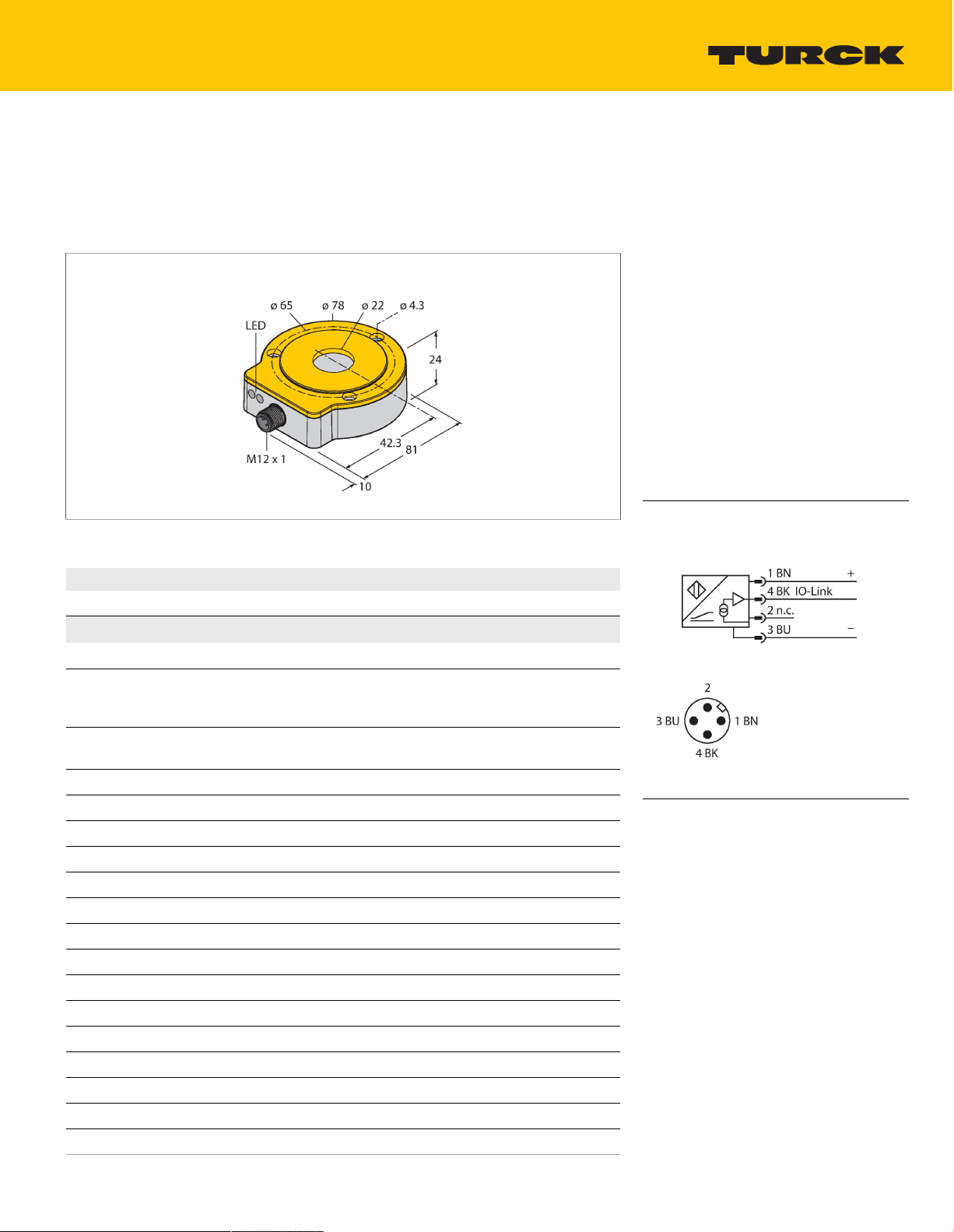
RI360P0-QR24M0-IOLX2-H1141
Contactless Encoder – IO-Link
Premium Line
Technical data
Features
Compact, rugged housing
■
Many mounting possibilities
■
Status displayed via LED
■
Immune to electromagnetic interference
■
16 bits singleturn
■
Process value in 32 bit IO-Link telegram
■
3 error bits
■
16 bits singleturn
■
13 bits multiturn
■
15…30 VDC
■
M12 × 1 male connector, 4-pin
■
Wiring diagram
Type
Ident. no. 1590975
Measuring principle
Max. Rotational Speed 800rpm
Starting torque shaft load (radial / axial) not applicable, because of contactless
Measuring range 0…360°
Nominal distance 1.5mm
Repeat accuracy ≤0.01% of full scale
Linearity deviation ≤0.05%f.s.
Temperature drift ≤ ±0.003% / K
Ambient temperature -25…+85°C
Operating voltage 15…30VDC
Residual ripple ≤10% U
Isolation test voltage ≤0.5kV
Wire breakage/Reverse polarity protection yes (voltage supply)
Output type Absolute semi-multiturn
Resolution singleturn 16bit/65,536 units per revolution
Resolution multiturn 13bit/8192 revolutions
Number of diagnostic bits 3Bit
Communication protocol IO-Link
RI360P0-QR24M0-IOLX2-H1141
Inductive
Determined with standardized
construction, with a steel shaft Ø 20 mm, L
= 50 mm and reducer Ø 20 mm
measuring principle
ss
Functional principle
The measuring principle of inductive encoders
is based on oscillation circuit coupling
between the positioning element and the
sensor, whereby an output signal is provided
proportional to the angle of the positioning
element. Turck refers to semi-multiturn because
the multiturn process data is calculated
internally from the number of single-turn
zero passes. Because the sensor does not
detect any revolutions when not supplied
with power, the plausibility of the multiturn
process data is indicated by a diagnostic
bit. The rugged sensors are maintenanceand wear-free thanks to the contactless
operating principle. They convince through
their excellent repeatability, resolution and
linearity within a broad temperature range. The
innovative technology ensures high immunity to
electromagnetic DC and AC fields.
RI360P0-QR24M0-IOLX2-H1141 | 12/03/2020 07-12 | technical changes reserved
TURCK Inc. | 3000 Campus Drive Minneapolis, MN 55441-2656 | Phone: 763-553-7300 | Application Support: 1-800-544-7769 | Fax 763-553-0708 | www.turck.com
1|5
Page 2

Technical data
Sample rate 1000Hz
Current consumption < 50 mA
IO-Link specification Specified acc. to version 1.1
Programming FDT/DTM
Communication mode COM 2 (38.4 kBaud)
Process data width 32bit
Minimum cycle time 3ms
Function Pin 4 IO-Link
Included in the SIDI GSDML Yes
Design
Dimensions 81x78x24mm
Flange type Flange without mounting element
Shaft Type Hollow shaft
Shaft diameter D [mm] 6
Housing material Metal/plastic, ZnAlCu1/PBT-GF30-V0
Electrical connection Connector,M12 × 1
Vibration resistance 55Hz (1 mm)
Vibration resistance (EN 60068-2-6) 20 g; 10…3000 Hz; 50 cycles; 3 axes
Shock resistance (EN 60068-2-27) 100 g; 11 ms ½ sinus; each 3x; 3 axes
Continuous shock resistance (EN
60068-2-29)
Protection class IP68 / IP69K
MTTF 138years acc. to SN 29500 (Ed. 99) 40
Power-on indication
Measuring range display LED, yellow, yellow flashing
QR24
6.35
9.525
10
12
12.7
14
15.875
19.05
20
40 g; 6 ms ½ sinus; each 4000 x; 3 axes
°C
LED,Green
TURCK Inc. | 3000 Campus Drive Minneapolis, MN 55441-2656 | Phone: 763-553-7300 | Application Support: 1-800-544-7769 | Fax 763-553-0708 | www.turck.com
RI360P0-QR24M0-IOLX2-H1141 | 12/03/2020 07-12 | technical changes reserved
2|5
Page 3

Mounting instructions
Mounting instructions/Description
Extensive range of mounting accessories
for easy adaptation to many different shaft
diameters. Based on the functional principle of
RLC coupling, the sensor operates absolutely
wear-free and is immune to magnetized metal
splinters and other interference fields. Wrong
installation is hardly possible.
The adjacent figure shows the two separate
units, sensor and positioning element.
Mounting option A:
First, interconnect positioning element and
rotatable shaft. Then place the encoder above
the rotating part in such a way that you get a
tight and protected unit.
Mounting option B:
Push the encoder on the back site of the shaft
and fasten it to the machine. Then clamp
the positioning element to the shaft with the
bracket.
Mounting option C:
If the positioning element is to be screwed on a
rotating machine part, use the RA0-QR24 plug
which is included in the delivery. Then tie up
the bracket. Screw on the encoder via the three
bores.
The separately arranged sensor and positioning
element inhibit that compensating currents or
damaging mechanical loads are transmitted via
the shaft to the sensor. In addition, the encoder
remains tight and highly protected during its
entire lifespan.
The accessories enclosed in the delivery help
to mount encoder and positioning element at an
optimal distance from each other. LEDs indicate
the switching status.
Status display via LED
green steady:
Optimal sensor supply
yellow steady:
Positioning element has reached the end of the
measuring range. This is indicated by a lower
signal quality.
yellow flashing:
Positioning element is outside the measuring
range.
off:
Positioning element is in the measuring range.
TURCK Inc. | 3000 Campus Drive Minneapolis, MN 55441-2656 | Phone: 763-553-7300 | Application Support: 1-800-544-7769 | Fax 763-553-0708 | www.turck.com
RI360P0-QR24M0-IOLX2-H1141 | 12/03/2020 07-12 | technical changes reserved
3|5
Page 4

Accessories
P1-RI-QR24 1590921
Positioning element, for Ø 20mm
shafts
P3-RI-QR24 1590923
Positioning element, for Ø 12mm
shafts
P5-RI-QR24 1590925
Positioning element, for Ø 6mm
shafts
P7-RI-QR24 1590927
Positioning element, for Ø 1/4“ shafts
P2-RI-QR24 1590922
Positioning element, for Ø 14mm
shafts
P4-RI-QR24 1590924
Positioning element, for Ø 10mm
shafts
P6-RI-QR24 1590926
Positioning element, for Ø 3/8“ shafts
P9-RI-QR24 1593012
Positioning element for installation on
Ø 1/2“ shafts
P10-RI-QR24 1593013
Positioning element for installation on
Ø 5/8“ shafts
P8-RI-QR24 1590916
Positioning element with blanking
plug for large shafts
PE1-QR24 1590937
Positioning element without adapter
sleeve
P11-RI-QR24 1593014
Positioning element for installation on
Ø 3/4“ shafts
M1-QR24 1590920
Aluminum protecting ring, for
inductive encoders RI-QR24
RA1-QR24 1590928
Adapter sleeve, for Ø 20 mm shafts
RI360P0-QR24M0-IOLX2-H1141 | 12/03/2020 07-12 | technical changes reserved
TURCK Inc. | 3000 Campus Drive Minneapolis, MN 55441-2656 | Phone: 763-553-7300 | Application Support: 1-800-544-7769 | Fax 763-553-0708 | www.turck.com
4|5
Page 5

RA2-QR24 1590929
Adapter sleeve, for Ø 14 mm shafts
RA3-QR24 1590930
Adapter sleeve, for Ø 12 mm shafts
RA4-QR24 1590931
Adapter sleeve, for Ø 10 mm shafts
RA6-QR24 1590933
Adapter sleeve, for Ø 3/8“ shafts
RA9-QR24 1590960
Adapter sleeve, for Ø 1/2" shafts
RA11-QR24 1590962
Adapter sleeve, for Ø 3/4" shafts
RA5-QR24 1590932
Adapter sleeve, for Ø 6 mm shafts
RA7-QR24 1590934
Adapter sleeve, for Ø 1/4“ shafts
RA10-QR24 1590961
Adapter sleeve, for Ø 5/8" shafts
RA8-QR24 1590959
Plug for mounting option C
SP1-QR24 1590938
Shield plate Ø 74 mm, aluminium
SP3-QR24 1590958
Shield plate Ø 52 mm, aluminium
SP2-QR24 1590939
Shield plate Ø 74 mm, aluminiuim,
with borehole for shaft feedthrough
MT-QR24 1590935
Mounting aid for optimal alignment of
positioning element
RI360P0-QR24M0-IOLX2-H1141 | 12/03/2020 07-12 | technical changes reserved
TURCK Inc. | 3000 Campus Drive Minneapolis, MN 55441-2656 | Phone: 763-553-7300 | Application Support: 1-800-544-7769 | Fax 763-553-0708 | www.turck.com
5|5
 Loading...