

Page 1
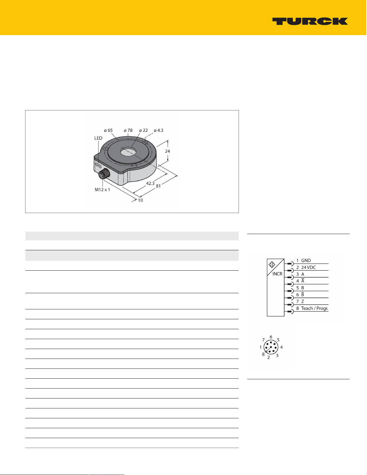
RI360P0-EQR24M0-INCRX2-H1181
Contactless Encoder with Stainless Steel Housing –
Incremental: 1 … 5000 ppr
Premium Line
Features
Compact, rugged housing
■
Active face, plastic PA12-GF30
■
Housing, stainless steel V4A (1.4404)
■
Status displayed via LED
■
Immune to electromagnetic interference
■
1024 pulses per revolution (default)
■
360, 512, 1000, 1024, 2048, 2500, 3600,
■
4096, parametr. via Easy-Teach
Free parametrization of the pulse number in
■
the range from 1 to 5000 via PACTware™
Position of z-track set via Easy-Teach
■
Burst function, absolute angular position
■
output incrementally per Easy-Teach pulse
10…30 VDC
■
Male M12 x 1, 8-pin
Technical data
■
Push-pull A, B, Z, A (inverse), B (inverse)
■
Type
Ident. no. 1590912
Measuring principle
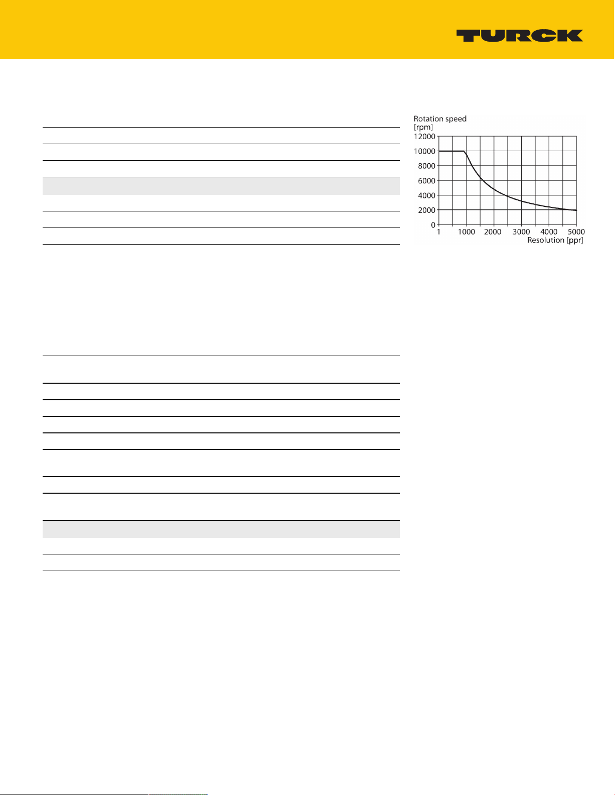
Max. Rotational Speed 10000rpm
Starting torque shaft load (radial / axial) not applicable, because of contactless
Nominal distance 1.5mm
Repeat accuracy ≤0.01% of full scale
Linearity deviation ≤0.05%f.s.
Temperature drift ≤ ±0.003% / K
Ambient temperature -25…+85°C
Operating voltage 10…30VDC
Residual ripple ≤10% U
Isolation test voltage ≤0.5kV
Short-circuit protection yes / Cyclic
Wire breakage/Reverse polarity protection yes / yes (voltage supply)
Output type Incremental
Resolution, incremental 1024ppr
Pulse frequency max. 200kHz
Signal level high min. UB - 2 V
RI360P0-EQR24M0-INCRX2-H1181
Inductive
Determined with standardized
construction, with a steel shaft Ø 20 mm, L
= 50 mm and reducer Ø 20 mm
measuring principle
ss
Wiring diagram
Functional principle
The measuring principle of inductive angle
sensors is based on oscillation circuit coupling
between the positioning element and the
sensor, whereby an output signal is provided
proportional to the angle of the positioning
element. The rugged sensors are wear and
maintenance-free, thanks to the contactless
operating principle. They convince through
their excellent repeatability, resolution and
RI360P0-EQR24M0-INCRX2-H1181 | 12/03/2020 06-55 | technical changes reserved
TURCK Inc. | 3000 Campus Drive Minneapolis, MN 55441-2656 | Phone: 763-553-7300 | Application Support: 1-800-544-7769 | Fax 763-553-0708 | www.turck.com
1|5
Page 2
Technical data
Signal level low max. 2.0V
Output function 8-pin, Push-Pull/HTL
Sample rate 1000Hz
Current consumption < 100 mA
Design
Dimensions 81x78x24mm
Flange type Flange without mounting element
Shaft Type Hollow shaft
Shaft diameter D [mm] 6
Housing material Stainless-steel/Plastic, 1.4404 (AISI 316L)/
Electrical connection Connector,M12 × 1
Vibration resistance 55Hz (1 mm)
Vibration resistance (EN 60068-2-6) 20 g; 10…3000 Hz; 50 cycles; 3 axes
Shock resistance (EN 60068-2-27) 100 g; 11 ms ½ sinus; 3 x each; 3 axes
Continuous shock resistance (EN
60068-2-29)
Protection class IP68 / IP69K
MTTF 138years acc. to SN 29500 (Ed. 99) 40
Power-on indication
Measuring range display LED, yellow, yellow flashing
Included in delivery Adapter sleeve MT-QR24
EQR24
6.35
9.525
10
12
12.7
14
15.875
19.05
20
PA12-GF30
40 g; 6 ms ½ sinus; each 4000 x; 3 axes
°C
LED,Green
linearity within a broad temperature range. The
innovative technology ensures a high immunity
to electromagnetic DC and AC fields.
TURCK Inc. | 3000 Campus Drive Minneapolis, MN 55441-2656 | Phone: 763-553-7300 | Application Support: 1-800-544-7769 | Fax 763-553-0708 | www.turck.com
RI360P0-EQR24M0-INCRX2-H1181 | 12/03/2020 06-55 | technical changes reserved
2|5
Page 3

Mounting instructions
Mounting instructions/Description
Extensive range of mounting accessories
for easy adaptation to many different shaft
diameters. Based on the functional principle of
RLC coupling, the sensor operates absolutely
wear-free and is immune to magnetized metal
splinters and other interference fields. Wrong
installation is hardly possible.
The adjacent figure shows the two separate
units, sensor and positioning element.
Mounting option A:
First, interconnect positioning element and
rotatable shaft. Then place the encoder above
the rotating part in such a way that you get a
tight and protected unit.
Mounting option B:
Push the encoder on the back site of the shaft
and fasten it to the machine. Then clamp
the positioning element to the shaft with the
bracket.
Mounting option C:
If the positioning element is to be screwed on a
rotating machine part and not on a shaft, install
first the dummy plug RA8-QR24. Then tie up
the bracket. Screw on the encoder via the three
bores.
The separately arranged sensor and positioning
element inhibit that compensating currents or
damaging mechanical loads are transmitted via
the shaft to the sensor. In addition, the encoder
remains tight and highly protected during its
entire lifespan.
The accessories enclosed in the delivery help
to mount encoder and positioning element at
an optimal distance from each other. LEDs
indicate the switching status. Optionally, you
can use the shields which are included in the
accessories to increase the allowed distance
between positioning element and sensor.
Status display via LED
green steady:
Sensor is operative
yellow steady:
Positioning element has reached the end of the
measuring range. This is indicated by a weaker
signal.
yellow flashing:
Positioning element is outside the measuring
range.
off:
Positioning element is in the measuring range
TURCK Inc. | 3000 Campus Drive Minneapolis, MN 55441-2656 | Phone: 763-553-7300 | Application Support: 1-800-544-7769 | Fax 763-553-0708 | www.turck.com
RI360P0-EQR24M0-INCRX2-H1181 | 12/03/2020 06-55 | technical changes reserved
3|5
Page 4

Individual Parameterization (Teaching with Positioning Element)
Jumper between teach
Gnd Pin 1 Ub Pin 2 LED
input Pin 8
2 s Z-track zero point
teaching
10 s CCW rotation
direction
One-time triggering of burst
function
Status LED flashes then
turns steady after 2 s
CW rotation direction After 10 s status LED
flashes fast for 2 s
15 s - Factory setting (z-track, CW) After 15 s power and
status LED alternate
To avoid unintended teaching, keep pin 8 potential-free.
Preset Programming Mode (Teaching without Positioning Element)
Jumper between teach
Gnd Pin 1 Ub Pin 2 LED
input Pin 8
2 s
Resolution setting
mode active for 10 s
2 s
Resolution setting
mode active for 10 s
Status LED steady, flashes after
2 s as long as selection mode is
active
360 pulses/360° Start value 1 x flashing
512 pulses/360° Press once 2 x flashing
1000 pulses/360° Press twice 3 x flashing
1024 pulses/360° Press three times 4 x flashing
2048 pulses/360° Press four times 5 x flashing
2500 pulses/360° Start value 1 x flashing
3600 pulses/360° Press once 2 x flashing
4096 pulses/360° Press twice 3 x flashing
5000 pulses/360° Press three times 4 x flashing
To avoid unintended teaching, keep pin 8 potential-free.
Accessories
PE1-EQR24 1590966
Positioning element with stainless
steel compression fitting, without
adapter sleeve
RA1-EQR24 1593019
Stainless steel adapter sleeve, for Ø
20 mm shafts
RA4-EQR24 1593023
Stainless steel adapter sleeve, for Ø
10 mm shafts
RA8-EQR24 100000289
Stainless steel plug for mounting
option C
M5-QR24 1590965
Plastic protecting ring for encoders
RI-EQR24
RA3-EQR24 1593020
Stainless steel adapter sleeve, for Ø
12 mm shafts
RA5-EQR24 100000375
Stainless steel adapter sleeve, for Ø 6
mm shafts
SP1-EQR24 1590979
Shield plate Ø 74 mm, stainless steel
TURCK Inc. | 3000 Campus Drive Minneapolis, MN 55441-2656 | Phone: 763-553-7300 | Application Support: 1-800-544-7769 | Fax 763-553-0708 | www.turck.com
RI360P0-EQR24M0-INCRX2-H1181 | 12/03/2020 06-55 | technical changes reserved
4|5
Page 5

SP5-QR24 100003689
Protective plate Ø 74 mm, plastic
Wiring accessories
Dimension drawing Type Ident. no.
RKCV8T-2/TFW 6934668 Connection cable, M12 coupling,
straight, 8-pin, stainless steel coupling
nut, cable length: 2 m, sheath
material: PP-EPDM, white; other cable
lengths and variants available, see
www.turck.com
RKC8T-2/TXL 6625142 Connection cable, female M12, straight,
RKC8.302T-1.5-RSC4T/TXL320 6625003 Adapter cable to connect sensor to
8-pin, cable length: 2 m, sheath
material: PUR, black; cULus approval;
other cable lengths and qualities
available, see www.turck.com
USB-2-IOL-0002 programming unit;
female M12, straight, 8-pin on male
M12, straight, 3-pin; cable length: 1.5
m; jacket material: PUR, jacket color:
black, cULus approved; RoHS conform;
protection class IP67
TURCK Inc. | 3000 Campus Drive Minneapolis, MN 55441-2656 | Phone: 763-553-7300 | Application Support: 1-800-544-7769 | Fax 763-553-0708 | www.turck.com
RI360P0-EQR24M0-INCRX2-H1181 | 12/03/2020 06-55 | technical changes reserved
5|5
 Loading...