

Page 1

Your Global Automation Partner
REM…|RES…
Encoders with SSI Interface
Instructions for Use
Page 2

2
Hans Turck GmbH & Co. KG | T +49 208 4952-0 | F +49 208 4952-264 | more@turck.com | www.turck.com
Page 3

Contents
1 About These Instructions.................................................................................................................. 5
1.1 Target groups................................................................................................................... 5
1.2 Explanation of symbols used ........................................................................................5
1.3 Other documents ............................................................................................................ 5
1.4 Feedback about these instructions.............................................................................. 5
2 Information About the Product .......................................................................................................6
2.1 Product identification..................................................................................................... 6
2.2 Scope of delivery .............................................................................................................6
2.3 Legal requirements.........................................................................................................6
2.4 Turck service..................................................................................................................... 6
3 For Your Safety.................................................................................................................................... 7
3.1 Intended use..................................................................................................................... 7
3.2 Obvious misuse................................................................................................................ 7
3.3 General safety notes .......................................................................................................7
4 Product Description ...........................................................................................................................8
4.1 Device overview .............................................................................................................. 8
4.2 Operating principle......................................................................................................... 8
4.3 Functions and operating modes ..................................................................................8
4.3.1 Output function................................................................................................................................ 8
4.3.2 Input function ...................................................................................................................................8
4.4 Technical accessories...................................................................................................... 9
5 Installing.............................................................................................................................................10
5.1 Mounting the solid shaft encoder using a coupling...............................................11
5.2 Mounting the hollow shaft encoder using a coupling...........................................12
6 Connection.........................................................................................................................................13
6.1 Wiring diagram ..............................................................................................................13
7 Commissioning .................................................................................................................................14
8 Setting ................................................................................................................................................15
8.1 Zero setting ....................................................................................................................15
8.2 Setting the rotation direction .....................................................................................15
8.3 Deactivating unused inputs ........................................................................................15
9 Troubleshooting ...............................................................................................................................16
10 Maintenance......................................................................................................................................17
11 Repair..................................................................................................................................................17
11.1 Returning devices..........................................................................................................17
12 Disposal ..............................................................................................................................................17
13 Turck Subsidiaries - Contact Information ....................................................................................18
V02.00 | 2021/04
3
Page 4

Contents
4
Hans Turck GmbH & Co. KG | T +49 208 4952-0 | F +49 208 4952-264 | more@turck.com | www.turck.com
Page 5
1 About These Instructions
These operating instructions describe the structure, functions and the use of the product and
will help you to operate the product as intended. Read these instructions carefully before using
the product. This is to avoid possible damage to persons, property or the device. Retain the instructions for future use during the service life of the product. If the product is passed on, pass
on these instructions as well.
1.1 Target groups
These instructions are aimed at qualified personal and must be carefully read by anyone
mounting, commissioning, operating, maintaining, dismantling or disposing of the device.
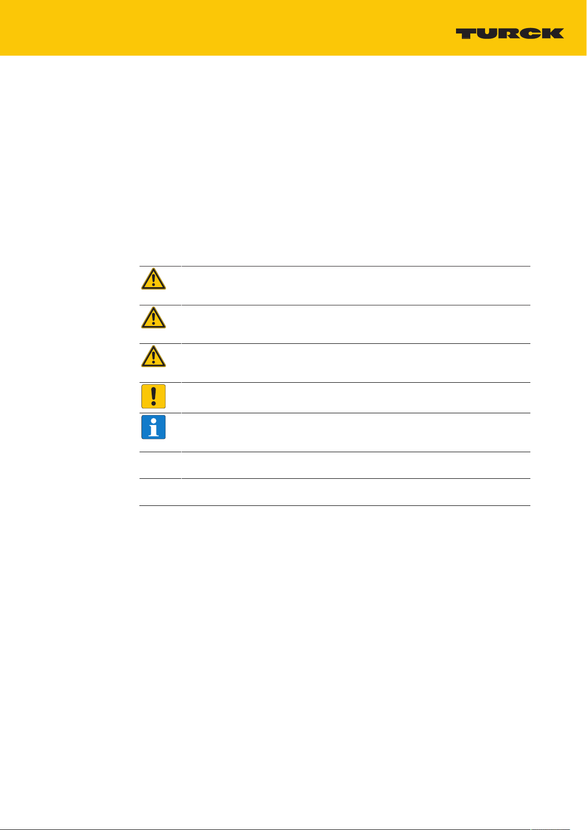
1.2 Explanation of symbols used
The following symbols are used in these instructions:
DANGER
DANGER indicates a dangerous situation with high risk of death or severe injury if
not avoided.
WARNING
WARNING indicates a dangerous situation with medium risk of death or severe injury if not avoided.
CAUTION
CAUTION indicates a dangerous situation of medium risk which may result in minor
or moderate injury if not avoided.
NOTICE
NOTICE indicates a situation which may lead to property damage if not avoided.
NOTE
NOTE indicates tips, recommendations and useful information on specific actions
and facts. The notes simplify your work and help you to avoid additional work.
u
a
CALL TO ACTION
This symbol denotes actions that the user must carry out.
RESULTS OF ACTION
This symbol denotes relevant results of actions.
1.3 Other documents
Besides this document the following material can be found on the Internet at www.turck.com:
n Data sheet
n Quick Start Guide
1.4 Feedback about these instructions
We make every effort to ensure that these instructions are as informative and as clear as
possible. If you have any suggestions for improving the design or if some information is missing
in the document, please send your suggestions to techdoc@turck.com.
V02.00 | 2021/04
5
Page 6

Information About the Product
Turck service
2 Information About the Product
2.1 Product identification
These instructions apply to the following encoders with SSI interface:
n RES-24
n RES-31
n RES-44
n RES-48
n RES-182
n RES-183
n RES-186
n RES-187
n REM-99
n REM-100
n REM-103
n REM-104
n REM-E-118
2.2 Scope of delivery
The scope of delivery includes:
n Encoder – sensor
n Quick Start Guide
2.3 Legal requirements
The devices are subject to the following EU directives:
n 2014/30/EU (electromagnetic compatibility)
n 2011/65/EU (RoHS Directive)
n 2012/19/EU (WEEE II)
2.4 Turck service
Turck supports you with your projects, from initial analysis to the commissioning of your application. The Turck product database under www.turck.com contains software tools for programming, configuration or commissioning, data sheets and CAD files in numerous export formats.
The contact details of Turck subsidiaries worldwide can be found on p. [}18].
6
Hans Turck GmbH & Co. KG | T +49 208 4952-0 | F +49 208 4952-264 | more@turck.com | www.turck.com
Page 7

3 For Your Safety
The product is designed according to state-of-the-art technology. However, residual risks still
exist. Observe the following warnings and safety notices to prevent damage to persons and
property. Turck accepts no liability for damage caused by failure to observe these warning and
safety notices.
3.1 Intended use
These devices are designed solely for use in industrial areas.
Encoders with an SSI interface are used to measure angular movements. To do this, the devices
absorb mechanical rotary movements and convert them into electrical pulse sequences. Per revolution, a defined number of pulses is emitted.
The devices may only be used as described in these instructions. Any other use is not in
accordance with the intended use. Turck accepts no liability for any resulting damage.
3.2 Obvious misuse
n The devices are not safety components and must not be used for personal or property
protection.
n Any use that exceeds the maximum permissible mechanical speed (see technical data) is
deemed to be not in accordance with the intended purpose.
3.3 General safety notes
n The device only meets the EMC requirements for industrial areas and is not suitable for use
in residential areas.
n The device may only be assembled, installed, operated, parameterized and maintained by
professionally-trained personnel.
n The device may only be used in accordance with applicable national and international
regulations, standards and laws.
n If safe operation is no longer guaranteed: Take the device out of operation and ensure that it
cannot be switched on again accidentally.
V02.00 | 2021/04
7
Page 8

Product Description
Functions and operating modes
4 Product Description
The encoders in the REM… and RES… product series with SSI interface are available as solid
shaft or hollow shaft versions. The REM…E product series contains only solid shaft devices.
Devices are available in three different sizes, ranging from 36 to 100 mm.
The SSI encoders output the absolute angular position in RS485 format.
4.1 Device overview
Fig.1: Example – encoder with hollow shaft Fig.2: Example – encoder with solid shaft
4.2 Operating principle
Encoders detect rotational movements, such as the angle velocity of a shaft. Encoders convert
the rotational movements into electrical signals. The devices pass on the electrical signals to a
higher-level controller for evaluation. Encoders are designed as absolute and incremental
encoders with hollow or solid shafts.
Absolute encoders also supply the angle value after a startup if the value has changed when
deactivated. Incremental encoders only detect position changes when active by counting
periodic patterns. This normally involves the optical scanning of a rotating disk.
4.3 Functions and operating modes
4.3.1 Output function
The output signal of the encoders with SSI interface is based on the RS485 protocol with a
permissible load of max. ±20mA. The clock rate is 50kHz-2MHz.
If the clock cycle starts within the monoflop time, a second data transfer starts with the same
data. When the clock cycle starts after the monoflop time, the cycle starts with new values. The
update rate depends on the clock speed, the data length, and the monoflop time.
4.3.2 Input function
The encoder is provided with a SET input and a DIR input. The inputs can be set via a
HIGH signal. The response time of the inputs is 1ms.
The write cycles for the SET input are limited to 10,000.
8
Hans Turck GmbH & Co. KG | T +49 208 4952-0 | F +49 208 4952-264 | more@turck.com | www.turck.com
Page 9

4.4 Technical accessories
M12 x 1 ø 15
42
L
50
5
Dimension drawing Type Ident-No. Description
E-RKC 8T-264-2 U-04781 Connection cable, female M12, straight, 8-pin,
cable length 2 m, sheath material: PVC, black;
other cable lengths and variants available, see
www.turck.com
V02.00 | 2021/04
9
Page 10

Installing
5 Installing
NOTICE
Incorrect mounting
Risk of damage to the sensor
Do not modify or disassemble the encoder.
Do not make adjustments to the shaft after mounting.
Do not use a hammer to align the device.
Avoid impact loads.
Load the encoder shaft only within the permissible values (see technical data).
Do not rigidly connect the rotary encoder to shafts and flanges at the same time.
Use the coupling between the drive shaft and the encoder shaft or the hollow
shaft encoder flange.
Fig.3: Mounting view – do not open Fig.4: Mounting view – do not make
adjustments after mounting
Fig.5: Mounting view – do not
use a hammer to align the device
Fig.6: Mounting view – do not rigidly connect
the device to shafts and flanges at the same
time
10
Hans Turck GmbH & Co. KG | T +49 208 4952-0 | F +49 208 4952-264 | more@turck.com | www.turck.com
Page 11

5.1 Mounting the solid shaft encoder using a coupling
D
M
α
Check shaft for displacement.
Refer to the technical data for the coupling for the maximum axial displacement, radial
displacement, and angular displacement values.
Fig.7: Axial displacement Fig.8: Radial displacement
Fig.9: Angular displacement
During mounting, protect the coupling against excessive bending and damage.
Align the coupling on the shaft.
Secure the coupling on the device using tensioning screws or clamping screws. For the
maximum tightening torque, refer to the data sheet of the screws used.
V02.00 | 2021/04
11
Page 12

Installing
Mounting the hollow shaft encoder using a coupling
5.2 Mounting the hollow shaft encoder using a coupling
Mount the encoder with the coupling on the shaft.
Fig.10: Mounting on the shaft with the coupling
Screw the coupling to the drive flange.
Fig.11: Screwing the coupling to the drive flange
Carefully tighten the clamping hub.
12
Fig.12: Tightening the clamping hub
Hans Turck GmbH & Co. KG | T +49 208 4952-0 | F +49 208 4952-264 | more@turck.com | www.turck.com
Page 13

6 Connection
1
2
3
4
5
6
7
8
PH
GND
U
B
CLOCK
CLOCK
DATA
DATA
SET (optional)
DIR (optional)
shield/PE
+
+
–
+
–
The encoder is provided with an 8-pin M12 x 1 male connector with an SSI interface. Refer to
the sensor label or data sheet for the pin layout.
Turck recommends the following cable lengths:
n For asymmetrical transmission (no inverted signals): max. 10m
n For symmetrical transmission (e.g. RS422 standard): max. 50m with twisted pairs
Connect all required cable cores as per the wiring diagram. Insulate the cable ends that
are not required to avoid short circuits.
Follow the operating instructions for the connecting cable used.
Disconnect the encoder from the connecting cable only when the encoder is de-ener-
gized.
Connect the shielding (if present) to the encoder housing.
The encoder and processor must always be switched on and off simultaneously.
Observe the operating voltage and maximum permissible output current (see technical
data).
CAUTION
Connecting and disconnecting during operation
Device damage possible
Only connect the device when it is in a de-energized state.
EMC-compliant installation
Use shielded connection cables as control cables.
For symmetrical transmission (e.g. via RS422): Use twisted pair cables.
Connect protective earth to the rotary encoder and the evaluation unit (low impedance).
Route the connection cables separately from cables with high noise levels.
Do not connect devices with high noise levels to the encoder's power supply
(e.g. frequency converters, solenoid valves, or contactors), or ensure that suitable voltage
filtering is in place.
6.1 Wiring diagram
Fig.13: Encoder REM SSI | RES SSI – Wiring diagram
V02.00 | 2021/04
13
Page 14

Commissioning
7 Commissioning
The device is operational automatically 150 ms after the connection is made and the power
supply is switched on.
14
Hans Turck GmbH & Co. KG | T +49 208 4952-0 | F +49 208 4952-264 | more@turck.com | www.turck.com
Page 15

8 Setting
8.1 Zero setting
NOTE
Only set the zero point when the device is at a standstill.
Put the application with the installed encoder in the required position.
Send a HIGH signal to the SET input for at least 10 ms. The HIGH signal must be at least
60% of the supply voltage.
a The zero point is set after 200ms.
8.2 Setting the rotation direction
The device is factory set to operate in a clockwise direction. The rotation direction can be
inverted as follows:
Send a HIGH signal to the DIR input for at least 10 ms. The HIGH signal must be at least
60% of the supply voltage.
a The rotation is set to the counterclockwise direction.
8.3 Deactivating unused inputs
Connect unused inputs to GND (0V) in order to prevent interference.
V02.00 | 2021/04
15
Page 16

Troubleshooting
9 Troubleshooting
If the device does not function as expected, first check whether ambient interference is present.
If there is no ambient interference present, check the connections of the device for faults.
If there are no faults, there is a device malfunction. In this case, decommission the device and
replace it with a new device of the same type.
16
Hans Turck GmbH & Co. KG | T +49 208 4952-0 | F +49 208 4952-264 | more@turck.com | www.turck.com
Page 17

10 Maintenance
Ensure that the plug connections and cables are always in good condition.
The devices are maintenance-free, clean dry if required.
11 Repair
The device must not be repaired by the user. The device must be decommissioned if it is faulty.
Observe our return acceptance conditions when returning the device to Turck.
11.1 Returning devices
Returns to Turck can only be accepted if the device has been equipped with a Decontamination
declaration enclosed. The decontamination declaration can be downloaded from
https://www.turck.de/en/retoure-service-6079.php
and must be completely filled in, and affixed securely and weather-proof to the outside of the
packaging.
12 Disposal
The devices must be disposed of correctly and must not be included in general
household garbage.
V02.00 | 2021/04
17
Page 18

Turck Subsidiaries - Contact Information
13 Turck Subsidiaries - Contact Information
Germany
Australia
Belgium
Brazil
China
France
Hans Turck GmbH & Co. KG
Witzlebenstraße 7, 45472 Mülheim an der Ruhr
www.turck.de
Turck Australia Pty Ltd
Building 4, 19-25 Duerdin Street, Notting Hill, 3168 Victoria
www.turck.com.au
TURCK MULTIPROX
Lion d'Orweg 12, B-9300 Aalst
www.multiprox.be
Turck do Brasil Automação Ltda.
Rua Anjo Custódio Nr. 42, Jardim Anália Franco, CEP 03358-040 São Paulo
www.turck.com.br
Turck (Tianjin) Sensor Co. Ltd.
18,4th Xinghuazhi Road, Xiqing Economic Development Area, 300381
Tianjin
www.turck.com.cn
TURCK BANNER S.A.S.
11 rue de Courtalin Bat C, Magny Le Hongre, F-77703 MARNE LA VALLEE
Cedex 4
www.turckbanner.fr
Great Britain
India
Italy
Japan
Canada
Korea
TURCK BANNER LIMITED
Blenheim House, Hurricane Way, GB-SS11 8YT Wickford, Essex
www.turckbanner.co.uk
TURCK India Automation Pvt. Ltd.
401-403 Aurum Avenue, Survey. No 109 /4, Near Cummins Complex,
Baner-Balewadi Link Rd., 411045 Pune - Maharashtra
www.turck.co.in
TURCK BANNER S.R.L.
Via San Domenico 5, IT-20008 Bareggio (MI)
www.turckbanner.it
TURCK Japan Corporation
Syuuhou Bldg. 6F, 2-13-12, Kanda-Sudacho, Chiyoda-ku, 101-0041 Tokyo
www.turck.jp
Turck Canada Inc.
140 Duffield Drive, CDN-Markham, Ontario L6G 1B5
www.turck.ca
Turck Korea Co, Ltd.
B-509 Gwangmyeong Technopark, 60 Haan-ro, Gwangmyeong-si,
14322 Gyeonggi-Do
www.turck.kr
18
Malaysia
Turck Banner Malaysia Sdn Bhd
Unit A-23A-08, Tower A, Pinnacle Petaling Jaya, Jalan Utara C,
46200 Petaling Jaya Selangor
www.turckbanner.my
Hans Turck GmbH & Co. KG | T +49 208 4952-0 | F +49 208 4952-264 | more@turck.com | www.turck.com
Page 19

Mexico
Turck Comercial, S. de RL de CV
Blvd. Campestre No. 100, Parque Industrial SERVER, C.P. 25350 Arteaga,
Coahuila
www.turck.com.mx
Netherlands
Austria
Poland
Romania
Russian
Federation
Sweden
Singapore
Turck B. V.
Postbus 297, NL-8000 AG Zwolle
www.turck.nl
Turck GmbH
Graumanngasse 7/A5-1, A-1150 Wien
www.turck.at
TURCK sp.z.o.o.
Wroclawska 115, PL-45-836 Opole
www.turck.pl
Turck Automation Romania SRL
Str. Siriului nr. 6-8, Sector 1, RO-014354 Bucuresti
www.turck.ro
TURCK RUS OOO
2-nd Pryadilnaya Street, 1, 105037 Moscow
www.turck.ru
Turck Sweden Office
Fabriksstråket 9, 433 76 Jonsered
www.turck.se
TURCK BANNER Singapore Pte. Ltd.
25 International Business Park, #04-75/77 (West Wing) German Centre,
609916 Singapore
www.turckbanner.sg
South Africa
Czech Republic
Turkey
Hungary
USA
Turck Banner (Pty) Ltd
Boeing Road East, Bedfordview, ZA-2007 Johannesburg
www.turckbanner.co.za
TURCK s.r.o.
Na Brne 2065, CZ-500 06 Hradec Králové
www.turck.cz
Turck Otomasyon Ticaret Limited Sirketi
Inönü mah. Kayisdagi c., Yesil Konak Evleri No: 178, A Blok D:4,
34755 Kadiköy/ Istanbul
www.turck.com.tr
TURCK Hungary kft.
Árpád fejedelem útja 26-28., Óbuda Gate, 2. em., H-1023 Budapest
www.turck.hu
Turck Inc.
3000 Campus Drive, USA-MN 55441 Minneapolis
www.turck.us
V02.00 | 2021/04
19
Page 20

100009124 | 2021/04
Over 30 subsidiaries and over
60 representations worldwide!
100009124
www.turck.com
 Loading...