

Page 1

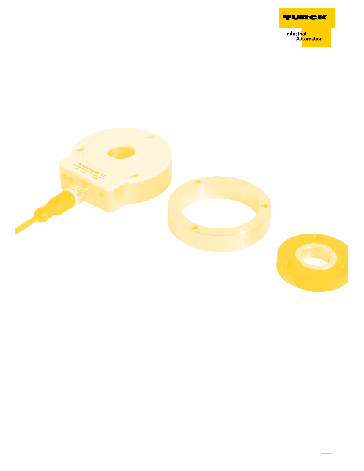
Sense it! Connect it! Bus it! Solve it!
CONTACTLESS
ENCODERS
WITH SSI
INTERFACE
USER
INFORMATION
Page 2
Hans Turck GmbH & Co. KG • Tel. +49 208 4952-0 • Fax +49 208 4952-264
2
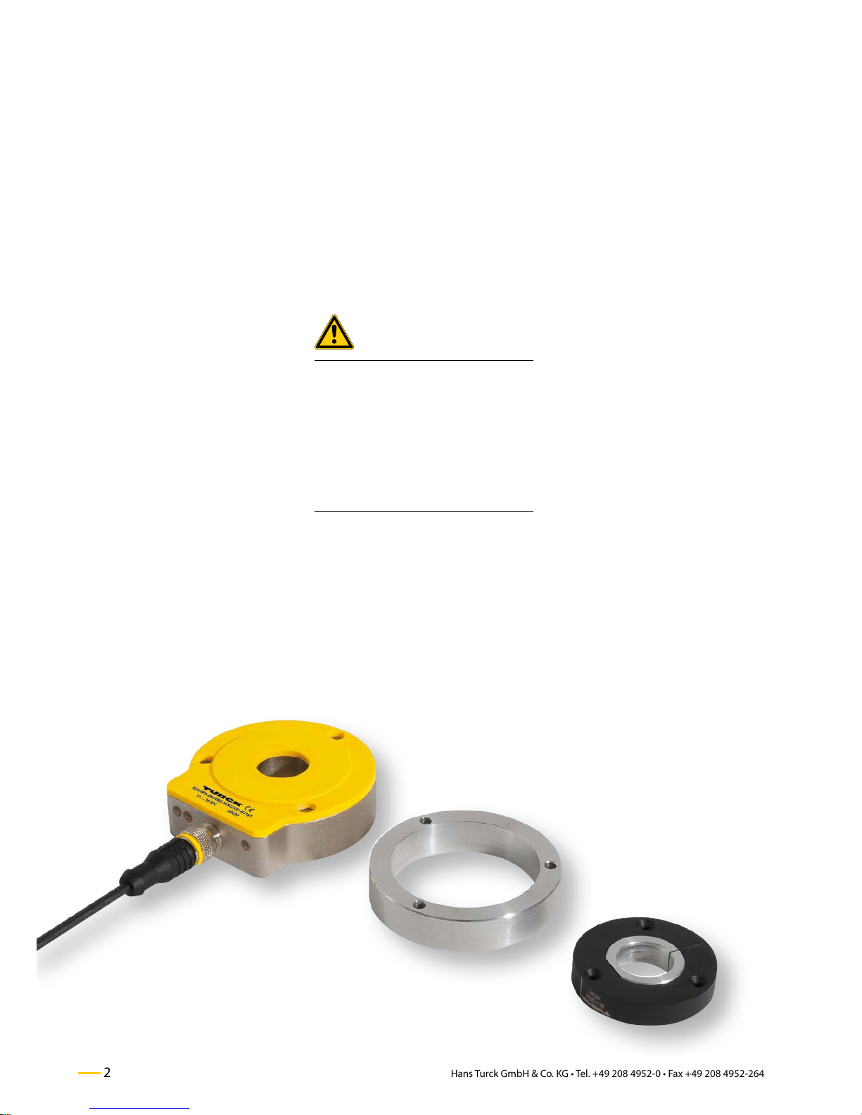
Contactless encoders with SSI interface –
General information
1 General information
Please read this section carefully. Safety as-
pects cannot be left to chance when dealing
with electrical equipment.
These directions of use contain the informa-
tion necessary for use of the inductive en-
coders Ri-QR24 from TURCK and is intended
for personnel with the necessary qualifica-
tions.
Prescribed use
Attention
The devices described hereafter must only
be used in the prescribed way and only
with certified components and devices from
third party manufacturers.
Appropriate transport, storage, deployment
and mounting as well as careful operating
and thorough maintenance guarantee the
troublefree and safe operation of these de-
vices.
Notes concerning planning /
installation of this product
Attention
All respective safety measures and accident
protection guidelines must be considered
carefully and without exception.
Safety note
WARNING
Due to improper fastening, the positioning element may loosen from mounting
position
Possible danger to life caused by loose
parts!
ӹ Follow the mounting instructions
carefully
ӹ Check tightness, tightening torque:
M = 0.6…0.8 Nm
Page 3
3
more@turck.com • www.turck.com • 2014/11
Contactless encoders with SSI interface –
Contents
Contactless encoders Ri-QR24 – with SSI Interface
1 General information ...................................................................... 2
2 Type code ................................................................................ 4
3 SSI interface description ...................................................... 5
4 Commissioning ..................................................................... 6
5 Mounting ............................................................................... 7
6 SSI process data .................................................................... 8
7 Parametrization via teach function .................................. 8
8 Parametrization via PACTware™ and IODD ..................... 9
9 Mounting accessories and positioning elements .......... 11
10 Technical data ........................................................................ 13
Page 4
Hans Turck GmbH & Co. KG • Tel. +49 208 4952-0 • Fax +49 208 4952-264
4
Contactless encoders with SSI interface –
Type code
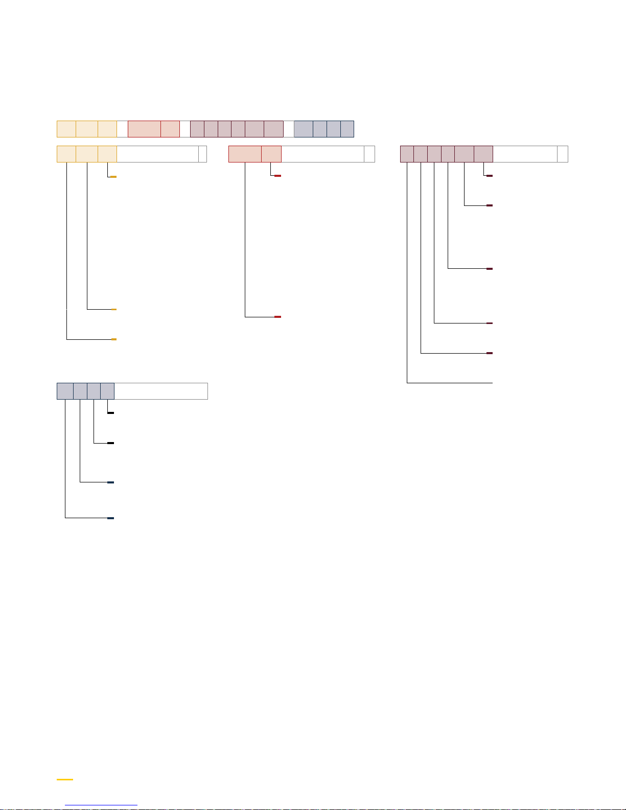
2 Type code
Note
The sensor, mounting accessories and posi-
tioning elements are individually available
or as a kit.
Ri 360 P1 – QR24 M1 – H E S G 25 X3 – H1 1 8 1
Ri 360 P1
Operating principle
–
Positioning element/
shaft diameter
P0 without positioning
element
P1 P1-Ri-QR24/20 mm*
P2 P2-Ri-QR24/14 mm*
P3 P3-Ri-QR24/12 mm*
P4 P4-Ri-QR24/10 mm*
P5 P5-Ri-QR24/6 mm*
P6 P6-Ri-QR24 / /"*
P7 P7-Ri-QR24 / /"*
P8 P8-Ri-QR24 / -
Measuring range
360 360°
Operating principle
Ri Rotatory inductive
QR24 M1
Housing style
–
Alu protective unit
M0 without alu
protective unit
M1 with alu
protective unit
M2 Set M2-QR24
(M1-QR24 +
SP1-QR24)
M3 Set M3-QR24
(M1-QR24 +
SP2-QR24)
M4 Set M4-QR24
(M1-QR24 +
SP3-QR24)
Housing style
QR24
H1 1 8 1
Electrical connection
Assignment (digit 5)
1 Standard assignment
Number of contacts
(digit 4)
8 8-pin M12 x 1
Connector type (digit 3)
1 straight
Connector type
(digit 1 and 2)
H1 Male connector
M12 x 1
H E S G 25 X3
Electrical version
–
Number of LEDs
X3 3 x LEDs
Number of bits
25 Number of bits
(default setting,
other values can
be set by the
customer)
Code
G Gray (default
setting, binary
can be set by the
customer)
SSI interface
S SSI interface
Resolution
E Higher resolution
Scan rate
H Higher scan rate
* Positioning elements with hollow shaft
Page 5

5
more@turck.com • www.turck.com • 2014/11
3 SSI interface
The encoders provide an absolute signal of
a guided or free positioning element. The
sensor is contactlessly coupled with the po-
sitioning element via a stable inductive RLC
circuit.
In addition to the indication of process val-
ues via current and voltage outputs, the SSI
interface (Synchronous Serial Interface) has
become an established alternative in the
field of industrial automation. The process
value is transmitted either directly to the
higher-level controller (with SSI-card) or
to an appropriate fieldbus participant that
connects to all standard fieldbuses, such as
piconet®, BL67, BL20 or BLcompact.
The advantage of the SSI-interface is that
signals are directly and digitally transmitted
via the SSI telegram and are therefore more
precise and immune to interferences. Not
only process data is transmitted via SSI tel-
egram but also diagnostic bits.
Contactless encoders with SSI interface –
SSI interface Description
The fieldbus device is the master com-
manding a clock signal to which the sen-
sor responds synchronously via the SSI
telegram. The clock rate and the data
frame length are specified by the master.
Depending on the length of the connection
cable different clock rates are recommend-
ed (see section "Commissioning" on page
6). In order to adapt the clock rate to the
cable length, it is adjustable on the master
side. The data frame length and the process
value displayed as Gray or binary code must
be the same on the master and sensor side.
The encoder position can be captured in the
SSI synchronous as well as in asynchronous
mode. You can toggle between both modes
with a DIP switch (see section "Parametriza-
tion via teach function ", page 8). The asyn-
chronous mode is factory set. This makes
the SSI encoder compatible with virtually all
major SSI masters.
Page 6

Hans Turck GmbH & Co. KG • Tel. +49 208 4952-0 • Fax +49 208 4952-264
6
Contactless encoders with SSI interface –
Commissioning
Status displayed via LED
■ green steady on:
Sensor is supplied properly, asynchronous
mode
■ green flashes:
Sensor is supplied properly, synchronous
mode
■ green flashes rapidly:
Sensor is supplied properly but is not
receiving CLK pulses from the SSI master
■ yellow steady on:
Positioning element has reached the end
of the measuring range. This is indicated
by a weaker signal, see status bit 23.
■ yellow flashing:
Positioning element is outside the measur-
ing range, see status bit 24.
Multiturn error
■ red steady on:
Position was changed during power loss,
see status bit 22
4 Commissioning
Sensor and SSI-master are linked with a con-
nection cable. In order to ensure proper data
traffic, it is recommended that you always
use shielded twisted-pair lines.
Make sure that the SSI-master and the sen-
sor have the same settings. The sensor's
type code contains the factory-set data
frame length of 25 bits as well as the Gray
code. The encoder adjusts itself automati-
cally to the specified master clock frequency
(62.5 kHz to 1 MHz).
In dependence on the transmission frequen-
cies, the following line lengths are recom-
mended:
Cable length Clock frequency
< 25 m < 1000 kHz
< 50 m < 500 kHz
< 100 m < 400 kHz
< 200 m < 200 kHz
< 400 m < 100 kHz
If the selected SSI-master doesn't provide
the request packets on time, operate the
sensor in the factory-set asynchronous
mode. This mode also works with an accu-
rately functioning master.
In time-critical applications, such as in the
control technology or motor commutation,
it is necessary that the encoder provides
extremely short and, in particular, constant
(synchronous) signal propagation times.
Here, the sensor must be operated in syn-
chronous mode together with a suitable
master. The sensor's sampling rate depends
on the master's SSI-cycle time, allowing syn-
chronous operation with SSI-cycle times of
700 Hz to 5 kHz. In synchronous mode, the
signal propagation delay is 200 µs, regard-
less of the cycle time. On selecting the SSI
master, note that a jitter of < 5 µs is required
in synchronous mode.
The nominal distance between positioning
element and sensor is 1.5 mm. Use the in-
cluded mounting aid MT-QR24 to adjust the
distance.
If positioning element and encoder are
mounted too far away from each other, the
signal will be weak. This status is indicated
by a steady yellow LED. If the distance be-
tween positioning element and encoder is
too large, i.e. RLC coupling is not given. This
status is indicated by a flashing yellow LED.
In addition, status bits within the SSI-process
data deliver diagnostic messages for proper
RLC coupling. If the encoder is moved dur-
ing a power cut, this is – after reconnecting
power – indicated by a red LED and a status
bit.
The encoder is factory set to a data frame
length of 25 bit. In this case, the singleturn
process data are found in bits 0 to 15 and
the multiturn process data in bits 16 to 21.
Bits 22 to 24 contain the diagnostic data.
You can apply further settings with the
software tool PACTware™, the TURCK pro-
gramming box USB-2-IOL-0002 (ident no.
6825482) and the associated adapter cable
RKC8.302T-1.5-RSC4T/TX320 (ident no.
6625003) as well as the IODD-file "IODD_
IOL_Ri-QR24.zip". (PACTware™ and IODD-file
can be downloaded from www.turck.com).
You can change the data frame length (24,
25 or 26 bit), the coding (Gray/binary) or the
distribution of the process data for example.
You can also disable the diagnostic data and
use the vacant bits for multiturn or single-
turn resolution instead. Only the singleturn
bits have to be set – the remaining bits in the
data packet are filled with the multiturn and
status bits accordingly (if these are enabled).
Page 7

7
more@turck.com • www.turck.com • 2014/11
5 Mounting
Extensive range of mounting accesso-
ries (see section "Mounting accessories"
on page 11) for easy adaptation to many
different shaft diameters. Based on the
functional principle of oscillation circuit
coupling, the sensor operates absolutely
wear-free and is immune to magnetized
metal splinters and other interference
fields. Wrong installation is hardly possible.
.
Contactless encoders with SSI interface –
Mounting
Warning
Due to improper fastening, the positioning element may loosen from mounting
position
Possible danger to life caused by loose
parts!
ӹ Follow the mounting instructions
carefully
ӹ Check tightness, tightening torque:
M = 0.6…0.8 Nm
6
2
1
5
4
3
2.5
A
0.6...0.8 Nm
SP2-QR24
6
2
1
5
4
3
2.5
A
C
0.6...0.8 Nm
SP2-QR24
4
3
1
2
2.5
0.6...0.8 Nm
0.6...0.8 Nm
SP3-QR24
2
3
5
6
4
2.5
1
B
1.4...1.5 Nm
0.6...0.8 Nm
SP1-QR24
ø 42
M4 x 0.5 x 7.5
In order to increase the allowed distance
between the positioning element and the
sensor you can optionally use the shields
SP1-QR24, SP2-QR24 or SP3-QR24.
The figures A, B, and C below show three
different ways of mounting the sensor and
the positioning element.
1 Use shielding plate SP2-QR24 optionally
2 Use mounting aid for optimal alignment
of positioning element
3 Place positioning element on the shaft
and make sure that the active face is
correctly aligned (see side label of posi-
tioning element)
4 Tighten the monting bracket with
Allen key
5 Remove mounting aid
6 Place encoder and protective ALcover
on the rotating part. Screw tight with
the three screws until you get a stable
and protected unit
1 Push the encoder from the rear on the
shaft and fasten it
2 Use mounting aid for optimal alignment
of positioning element
3 Interconnect positioning element and
rotatable shaft. Make sure that the ac-
tive face is correctly aligned (see side la
bel of positioning element)
4 Tighten the clamping bracket with
Allen key
5 Remove mounting aid
6 The protective Al cover and the shield-
ing plate SP1-QR24 can be used option-
ally
If positioning element is to be screwed on a
rotating machine part:
1 Use the RA8-QR24 plug which is includ-
ed in the delivery
2 Tighten the clamping bracket with
Allen key
3 Use shielding plate SP3-QR24 optionally
4 Fixate positioning element with three
M3 countersunk head screws
Mount encoder as required
Page 8

Hans Turck GmbH & Co. KG • Tel. +49 208 4952-0 • Fax +49 208 4952-264
8
Contactless encoders with SSI interface –
SSI process data/Parametrization
6 SSI-Prozess data
7 Parametrization via easy teach function
6.1 Process data mapping, diagnostic data active
Position Singleturn Bit 0 ... Bit [ singleturn bit length – 1] LSB
Multiturn counter (SSI bit length 25 bit) Bit [singleturn bit length]…Bit [SSI word length – 3] …
Multiturn counter (SSI bit length 26 bit) Bit [singleturn bit length]…Bit [SSI word length – 4] …
1 Multiturn error Bit 22 (see note below) …
2 Amplitude weak Bit 23 (see note below) …
3 Amplitude error Bit 24 (see note below) MSB
Note
If the SSI word length is less than 25 bits, the diagnostic data 1 to 3 automatically become inactive.
Note that the SSI word length can be modied via PACTware™ (see parameter" SSI bit length", page 10)!
6.2 Process data mapping, diagnostic data inactive
Position Singleturn Bit 0 ... Bit [ singleturn bit length – 1]
Multiturn counter Bit [singleturn bit length]…Bit [SSI word length – 1]
Denitions
Bit 0: LSB (least signicant bit)
Singleturn bit length = parametrized resolution for a full revolution (10…18 bit)
SSI word length = parametized SSI bit length (24…26 bit)
The encoder can be adjusted via "easy
teach function". Pin 8 is used as teach in-
put (see wiring diagram on page 13).
The parameters are adjusted by bridging
Pin 8 and Pin 1 (GND) or Pin 8 and Pin 2 (U
B
).
For simple teaching with DIP switch use the
optionally available teach adapter TX2-
Q20L60 with the ident no. 6967117.
Parameters Teach input LED display Description
Zero point bridge Pin 1 (GND) and
Pin 8 for 2 s
status LED ashes, after 2 s steady the encoder's position is set as zero point
Switching between
sync/async mode
bridge Pin 2 (U
B
) and Pin
8 for 2 s
status LED ashes, after 2 s steady
power LED steady green: async mode,
power LED ashes green: sync mode
async mode default set;
encoder switches between async/sync
mode by means of a teach pulse
Direction mode bridge Pin 2 (U
B
) and Pin
8 for 10 s
after 10 s status LED ashes for 2 s encoder rotates in CW direction (factory
setting)
bridge Pin 1 (GND) and
Pin 8 for 10 s
after 10 s status LED ashes for 2 s encoder rotates in CCW direction
Multiturn error ag bridge Pin 1 (GND) and
Pin 8 for 15 s
after 15 s, power and status LED ash
alternately
multiturn error ag is deleted
Switching between
singleturn/multiturn
mode
bridge Pin 2 (U
B
) and Pin 8
for 20 s
after 10 s, the red LED ashes Validity depends on revision status
Easy teach reset bridge Pin 2 (U
B
) and Pin 8
for 15 s
after 15 s, power and status LED ash
alternately
the following parameter are restored:
CW rotation, zero point, multiturn error
(delete), multiturn counter (zero)
Page 9

9
more@turck.com • www.turck.com • 2014/11
8 Parametrization via PACTware™ and IODD
Contactless encoders with SSI interface –
Parametrization
8.1 Software download and install
You can download PACTware™, the IODD-
interpreter and the encoder IODD-file from
www.turck.com. Once you have installed
PACTware™, activate the "IODD_IOL_Ri-
QR24..zip" file with the IODD-interpreter and
update the device catalog in PACTware™.
8.2 Set Parameters
The following encoder parameters can be
set in PACTware™:
Page 10

Hans Turck GmbH & Co. KG • Tel. +49 208 4952-0 • Fax +49 208 4952-264
10
Contactless encoders with SSI interface –
Parametrization
1
) This parameter is not adjustable via "Easy teach function".
MSB
…
LSB
Error Multiturn Singleturn
Bit 24…Bit 22 Bit 21…Bit 16 Bit 15…Bit 0
8.4 Factory setting SSI-Process data
8.3 Detailed list of adjustable parameters
Parameters Description
Multiturn reset In multiturn mode multiturn process data is stored in the encoder even after power loss. This means
that the device continues to count with the stored multiturn value after power recovery.
If the positioning element was relocated during a power loss, this is indicated by a status bit (multiturn error ag) and a red LED.
This incident and the multiturn data are reset with this command.
SSI bit length 23, 24, 25, or 26 bit are parametrizable (factory setting "25 Bit")
SSI singleturn bit length
1
) 10 to 18 bit are parametrizable.
Depending on the setting, the following assignments for singleturn process data are used:
bits 0 to 9 (10 bit), or bits 0 to 17 (18 bit). (factory setting "16 Bit“)
SSI Code (Gray/binary)
1
) Bit coding (Gray, binary) parametrizable (factory setting "Gray")
SSI mode
(async/auto-sync/sync)
Parametrization of the encoder for operation with sync (deterministic) SSI-master (jitter < 5 µs) or
async SSI-master.
In sync mode the signal propagation time is optimal.
(Factory setting "Async")
SSI ags enabled
1
) Bits 22, 23, 24 provide status information. These status bits can be disabled in this command. The va-
cated bits are used in this case for the multiturn process data. If 23 or 24 bit are parametrized under
SSI bit length, the SSI ags will automatically be disabled.
(Factory setting "SSI Flags On")
zero point Both singleturn as well as multiturn process data and the multiturn error ag will be reset.
Direction mode The direction can be parametrized from clockwise to counterclockwise as appropriate.
(Factory setting "CW Clockwise" in plan view on the positioning element)
factory setting
1
) All parameters are reset to factory setting.
Page 11

11
more@turck.com • www.turck.com • 2014/11
Dimension drawing Type Description
60
30
50
20
M12 x 1
M12 x 1
42.5
ø 15
ø 4.5
8
TX2-Q20L60 Teach adapter for easy program-
ming
USB-2-IOL-0002 IO-Link master with integrated
USB interface for parametrizing
the IO-Link-capable encoders
via a PC
without figure RKC8.302T-1,5-
RSC4T/TX320
Adapter cable for connection
of SSI sensor to USB-2-IOL-0002
parametrizing unit; female M12,
straight, 8-pin - male M12,
straight, 3-pin; cable length:
1.5 m; sheath material: PVC;
sheath color: black; cULus approved, RoHS conform, IP67
rated
ø 24
ø 28
2
9.9
ø 20
RA1-QR24
RA2-QR24
RA3-QR24
RA4-QR24
RA5-QR24
RA6-QR24
RA7-QR24
Reducing bushing, for Ø 20 mm
shafts
Reducing bushing, for Ø 14 mm
shafts
Reducing bushing, for Ø 12 mm
shafts
Reducing bushing, for Ø 10 mm
shafts
Reducing bushing, for Ø 6 mm
shafts
Reducing bushing, for Ø 3/8"
shafts
Reducing bushing, for Ø 1/4"
shafts
ø 24
ø 28
2
9.9
RA8-QR24 Blanking plug for positioning
element
1.5
MT-QR24 Mounting aid for optimal align-
ment of positioning element
9 Accessories
9.1 Mounting accessories
For accessories, see the table below.
Contactless encoders with SSI interface –
Mounting accessories
Set Description
M1-QR24 Protective ring, aluminium
ø 74
ø 4.5
ø 65
ø 57
120°
14.3
M2-QR24 M1-QR24 +
SP1-QR24
shielding plate
Ø 74 mm, aluminium
ø 74
ø 4.5
ø 65
120°
2
M3-QR24 M1-QR24 +
SP2-QR24
shielding plate
Ø 74 mm with bore with shaft
guidance, aluminium
ø 74
ø 4.5
ø 65
ø 22
120°
2
M4-QR24 M1-QR24 +
SP3-QR24
shielding plate
Ø 52 mm, aluminium
ø 52
ø 3.2
ø 42
120°
2
41
24
54
M12 x 1
16
USB-Mini
IN-DC
LED:
CH1 (C/Q)
CH2 (DI/DO)
Error
LED: PWR
9.2 Standard mounting accessories
For each device type a suitable mount-
ing kit is available (see Type Code, Design,
page 4. The mounting kits contain the
M1-QR24 aluminium ring for protection
and a shielding plate (either SP1-QR24 or
SP2-QR24 orSP3-QR24).
Page 12

Hans Turck GmbH & Co. KG • Tel. +49 208 4952-0 • Fax +49 208 4952-264
12
Contactless encoders with SSI interface –
Accessories positioning elements
9.3 Positioning elements
Different positioning elements are available.
The positioning elements are connected
to the movable parts of the machine. They
"float" freely above the active face of the
sensor.
Dimension drawing Type Description
ø 3.2
ø 20
ø 52
ø 42
10
P1-Ri-QR24 Positioning element,
for Ø 20 mm shafts
ø 3.2
ø 52
ø 42
10
ø 14
P2-Ri-QR24 Positioning element,
for Ø 14 mm shafts
ø 3.2
ø 52
ø 42
10
ø 12
P3-Ri-QR24 Positioning element,
for Ø 12 mm shafts
ø 3.2
ø 52
ø 42
10
ø 10
P4-Ri-QR24 Positioning element,
for Ø 10 mm shafts
ø 3.2
ø 52
ø 42
10
ø 6
P5-Ri-QR24 Positioning element,
for Ø 6 mm shafts
ø 3.2
ø 52
ø 42
10
ø 3/8“
P6-Ri-QR24 Positioning element,
for Ø 3/8" shafts
ø 3.2
ø 52
ø 42
10
ø 1/4“
P7-Ri-QR24 Positioning element,
for Ø 1/4" shafts
ø 3.2
ø 52
ø 42
10
P8-Ri-QR24 Positioning element with blank-
ing plug
Page 13

13
more@turck.com • www.turck.com • 2014/11
ø 78 ø 22 ø 4.3 ø 65
24
81
10
42.3
LED
M12 x 1
Measuring range
Measuring range 0…360 °
single or multiturn mode
System
Resolution
Repeatability
Linearity tolerance
Temperature drift
Ambient temperature
16-bit
0.01 %
≤ 0.05 % full scale.
≤ ± 0.003 %/K
-25…+85 °C
Electrical data
Operating voltage
Ripple
Rated insulation voltage
Reverse polarity protection
Output function
Process data range
Diagnostic bits
Sampling rate
Current consumption
15…30 VDC
≤ 10 % U
ss
≤ 0.5 kV
yes (power supply)
8-wire, SSi, 25-bit, gray coded
parametrizable
Bit 22: Position changed during a power loss
Bit 23: Positioning element is in the measuring range, reduced signal quality (e.g. distance too large)
Bit 24: Positioning element is outside of measuring range
data telegram parametrizable as multiturn or singleturn process data or as error bits
5000 Hz/the sensor's sampling rate depends on the master's SSI cycle time. It is 1 to 5 kHz (signal
propagation delay 200 s) in sync mode
< 100 mA
Housing
Dimensions
Housing material
Connection
Vibration resistance
Shock resistance
Degree of protection
MTTF
81 × 78 × 24 mm
metal/plastic, ZnAlCu1/PBT-GF30-V0
male connector, M12 × 1
EN 60068-2-6, 55 Hz
EN 60068-2-27, 30 g
IP67/IP69K
138 years to SN 29500 (Ed. 99) 40 °C
LEDs
Operating voltage indication
Measuring range indication
Fault indication
LED green
LED, yellow, yellow flashing
LED red
Miscellaneous
Included in scope of supply mounting aid MT-QR24
Wiring diagram
1 GND
2 24 VDC
3 CLK +
4 CLK –
5 Data +
6 Data –
7 n.c.
8 Te ach / Progr.
SSI
Contactless encoders with SSI interface –
Technical data
10 Technical data
Page 14

D102003 2014/11
*D102003ßß1411*
Hans Turck GmbH & Co. KG
Witzlebenstr. 7
45472 Muelheim an der Ruhr
Germany
Tel. +49 208 4952-0
Fax +49 208 4952-264
E-Mail more@turck.com
Internet www.turck.com
WORLDWIDE HEADQUARTERS
Your Global
Automation Partner!
 Loading...