

Page 1
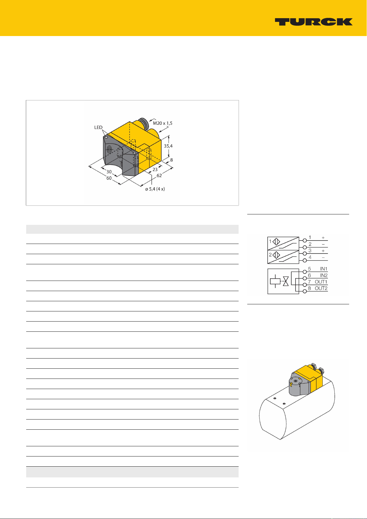
NI4-DSU35TC-2Y1X2/S97
Inductive Sensor – Dual Sensors with Extended Temperature
Range
Features
Rectangular, housing DSU35
■
Plastic, PP-GF30-VO
■
Two outputs for monitoring the position of
■
rotary actuators
Mounting on all standard actuators
■
Temperatures up to -40 °C
■
DC 2-wire, nom. 8.2 VDC
■
2 outputs acc. to DIN EN 60947-5-6 (NA-
■
MUR)
Terminal chamber
■
ATEX category II 2 G, Ex zone 1
■
ATEX category II 1 D, Ex-zone 20 for tem-
■
peratures up to -25°C
SIL2 acc. to IEC 61508
■
Technical data
Wiring diagram
Type
ID no. 1051017
Rated switching distance 4mm
Mounting conditions Non-flush
Correction factors St37 = 1; Al = 0.3; stainless steel = 0.7;
Repeat accuracy ≤2% of full scale
Temperature drift ≤ ± 10 %
Hysteresis 1…10%
Ambient temperature -40…+70°C
Output function 4-wire, NAMUR
Valve control Exi (max. 30 V)
Switching frequency 0.05kHz
Voltage Nom.8.2VDC
Non-actuated current consumption ≥2.1mA
Actuated current consumption ≤1.2mA
Approval acc. to KEMA 02 ATEX 1090X
Internal capacitance (Ci)/inductance (Li) 150 nF/150 µH
Device marking
Warning Avoid static charging
Design
Dimensions 62x60x35.4mm
NI4-DSU35TC-2Y1X2/S97
Ms = 0.4
≤ ± 20 %, ≤ ‐25 °C
For explosion hazardous areas see instruction leaflet
É II 2 G Ex ia IIC T6 Gb / II 1 D Ex ia IIIC T95 °C Da
(max. Ui = 20 V, Ii = 60 mA, Pi = 200 mW)
Dual sensor for rotary actuators,DSU35
Functional principle
Inductive sensors detect metal objects
contactless and wear-free. Dual sensors are
especially designed for position detection in
rotary actuators. They combine the reliability
of non-contact inductive sensors with the
flexibility of a modular housing system.
NI4-DSU35TC-2Y1X2/S97 | 22-04-2021 15-55 | Technical modifications reserved
Hans Turck GmbH & Co. KG | 45466 Mülheim an der Ruhr, Germany | T +49 208 4952-0 | F +49 208 4952-264 | more@turck.com | www.turck.com 1|3
Page 2
Technical data
Housing material Plastic, PP-GF30, Yellow
Active area material Plastic, PP-GF30, black
Max. tightening torque of housing nut 3Nm
Electrical connection Terminal chamber
Clamping ability
≤2.5mm
2
Vibration resistance 55Hz (1 mm)
Shock resistance 30g (11 ms)
Protection class IP67
MTTF 2283years acc. to SN 29500 (Ed. 99) 40
°C
Switching state 2 × LEDs,Yellow/Red
Included in delivery 2 cable glands (blue), 1 blanking plug
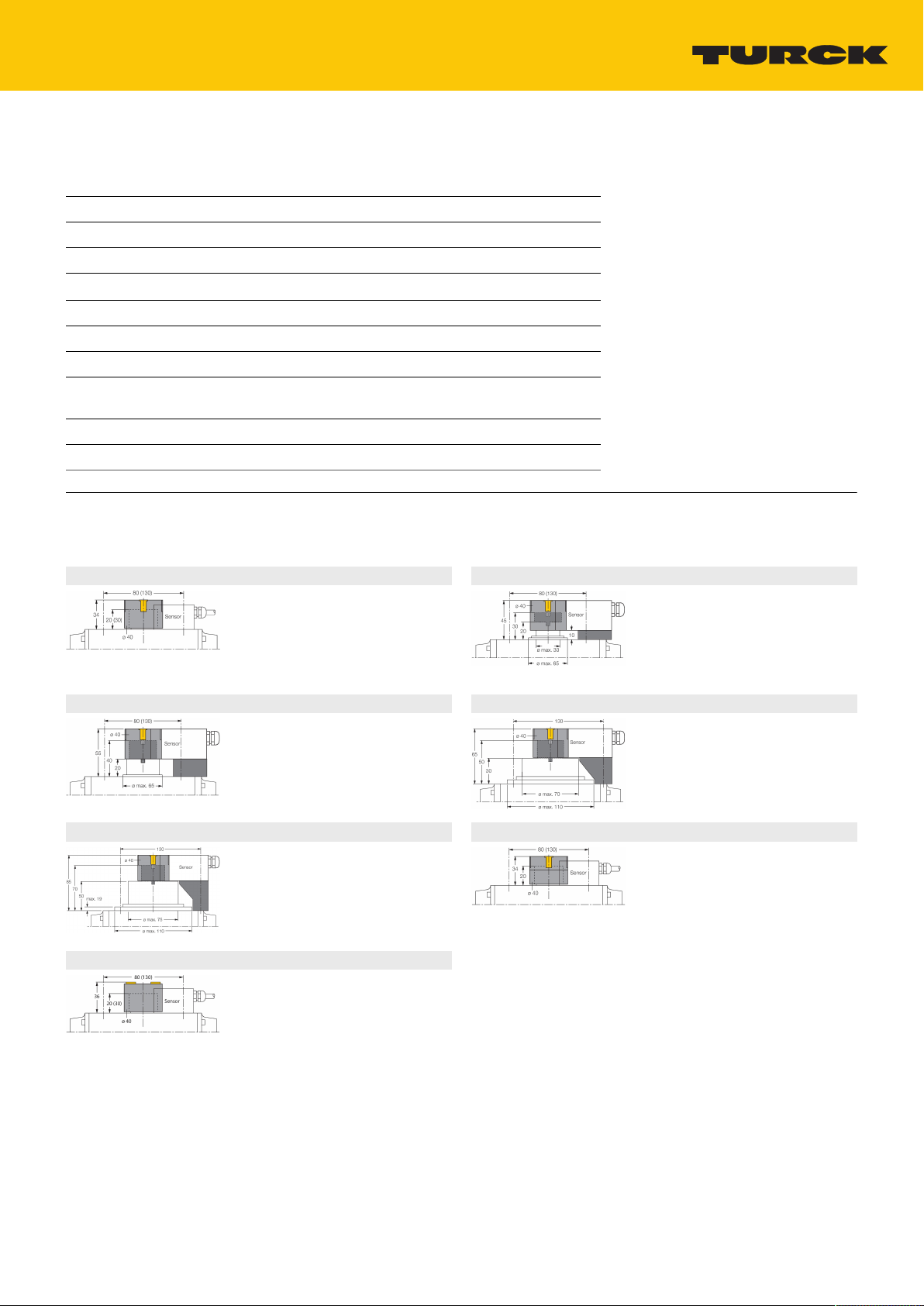
Accessories
BTS-DSU35-EB1 6900225
Actuation kit (puck) for dual sensors;
end position damped; hole pattern on
receptacle surface: 80 x 30mm and
130 x 30mm; connection shaft (shaft
extension) height: 20mm (30mm)/Ø:
max. 30mm
BTS-DSU35-Z02 6900230
Mounting kit for dual sensors for
larger rotary actuators; Ø spacer plate
and snap ring: max. 65mm; hole
pattern on receptacle surface: 30 x
80mm (30 x 130mm); connection
shaft (shaft extension) height: 20mm
(30mm)/Ø: max. 40mm
BTS-DSU35-Z07 6900403
Mounting kit for dual sensors for
larger rotary actuators; Ø spacer plate
and snap ring: max. 110mm; hole
pattern on receptacle surface: 30
x 130mm; connection shaft (shaft
extension) height: 50mm/Ø: max.
75mm
BTS-DSU35-EU2 6900455
Actuation kit (puck) for dual sensors;
end position undamped for clockwise
and counter-clockwise drives; hole
pattern on flange surface 80 x 30 mm
and 130 x 30 mm; connection shaft
(shaft stud) height 20 (30) mm / Ø
max. 30 mm
BTS-DSU35-Z01 6900229
Mounting kit for dual sensors for
larger rotary actuators; Ø spacer plate
and snap ring: max. 65mm; hole
pattern on receptacle surface: 30 x
80mm (30 x 130mm); connection
shaft (shaft extension) height: 20mm/
Ø: max. 30mm
BTS-DSU35-Z03 6900231
Mounting kit for dual sensors for
larger rotary actuators; Ø spacer plate
and snap ring: max. 110mm; hole
pattern on receptacle surface: 30
x 130mm; connection shaft (shaft
extension) height: 30mm/Ø: max.
70mm
BTS-DSU35-EBE3 6901070
Actuation kit (puck) for dual sensors;
end position damped; "open" and
"closed" switchpoint adjustable; hole
pattern on receptacle surface: 80 x
30mm and 130 x 30mm; connection
shaft (shaft extension) height: 20mm/
Ø: max. 30mm
Hans Turck GmbH & Co. KG | 45466 Mülheim an der Ruhr, Germany | T +49 208 4952-0 | F +49 208 4952-264 | more@turck.com | www.turck.com 2|3
NI4-DSU35TC-2Y1X2/S97 | 22-04-2021 15-55 | Technical modifications reserved
Page 3

Operating Instructions
Intended use This device fulfills the directive 2014/34/EC and is suit-
ed for use in explosion hazardous areas according to EN
60079-0:2012 + A11 and EN 60079-11:2012.Further it is suited for use in safety-related systems, including SIL2 as per IEC
61508.In order to ensure correct operation to the intended purpose it is required to observe the national regulations and directives.
For use in explosion hazardous areas conform to classification II 2 G and II 1 D (Group II, Category 2 G, electrical equipment
for gaseous atmospheres and category 1 D, electrical equipment for dust atmospheres).
Marking (see device or technical data sheet)
Local admissible ambient temperature ATEX category II 2 G electrical equipment -40…+70°C, cat-
Installation/Commissioning These devices may only be installed, connected and oper-
Installation and mounting instructions Avoid static charging of cables and plastic devices. Please
Special conditions for safe operation avoid static charging
Service/Maintenance Repairs are not possible. The approval expires if the device is
É II 2 G and Ex ia IIC T6 Gb and É II 1 D Ex ia IIIC T95 °C
Da acc. to EN 60079-0, -11
egory II 1 D -25…+70 °C. The corresponding temperature
classes are provided in the ATEX type-examination certificate.
ated by trained and qualified staff. Qualified staff must have
knowledge of protection classes, directives and regulations
concerning electrical equipment designed for use in explosion
hazardous areas.Please verify that the classification and the
marking on the device comply with the actual application conditions.
This device is only suited for connection to approved Exi circuits according to EN 60079-0 and EN 60079-11. Please observe the maximum admissible electrical values.After connection to other circuits the sensor may no longer be used in
Exi installations. When interconnected to (associated) electrical equipment, it is required to perform the "Proof of intrinsic
safety" (EN60079-14).Attention! When used in safety systems,
all content of the security manual must be observed.
only clean the device with a damp cloth. Do not install the
device in a dust flow and avoid build-up of dust deposits on
the device.If the devices and the cable could be subject to
mechanical damage, they must be protected accordingly.
They must also be shielded against strong electro-magnetic
fields.The pin configuration and the electrical specifications
can be taken from the device marking or the technical data
sheet.In order to avoid contamination of the device, please remove possible blanking plugs of the cable glands or connectors only shortly before inserting the cable or opening the cable socket.
repaired or modified by a person other than the manufacturer.
The most important data from the approval are listed.
Hans Turck GmbH & Co. KG | 45466 Mülheim an der Ruhr, Germany | T +49 208 4952-0 | F +49 208 4952-264 | more@turck.com | www.turck.com 3|3
NI4-DSU35TC-2Y1X2/S97 | 22-04-2021 15-55 | Technical modifications reserved
 Loading...