

Page 1
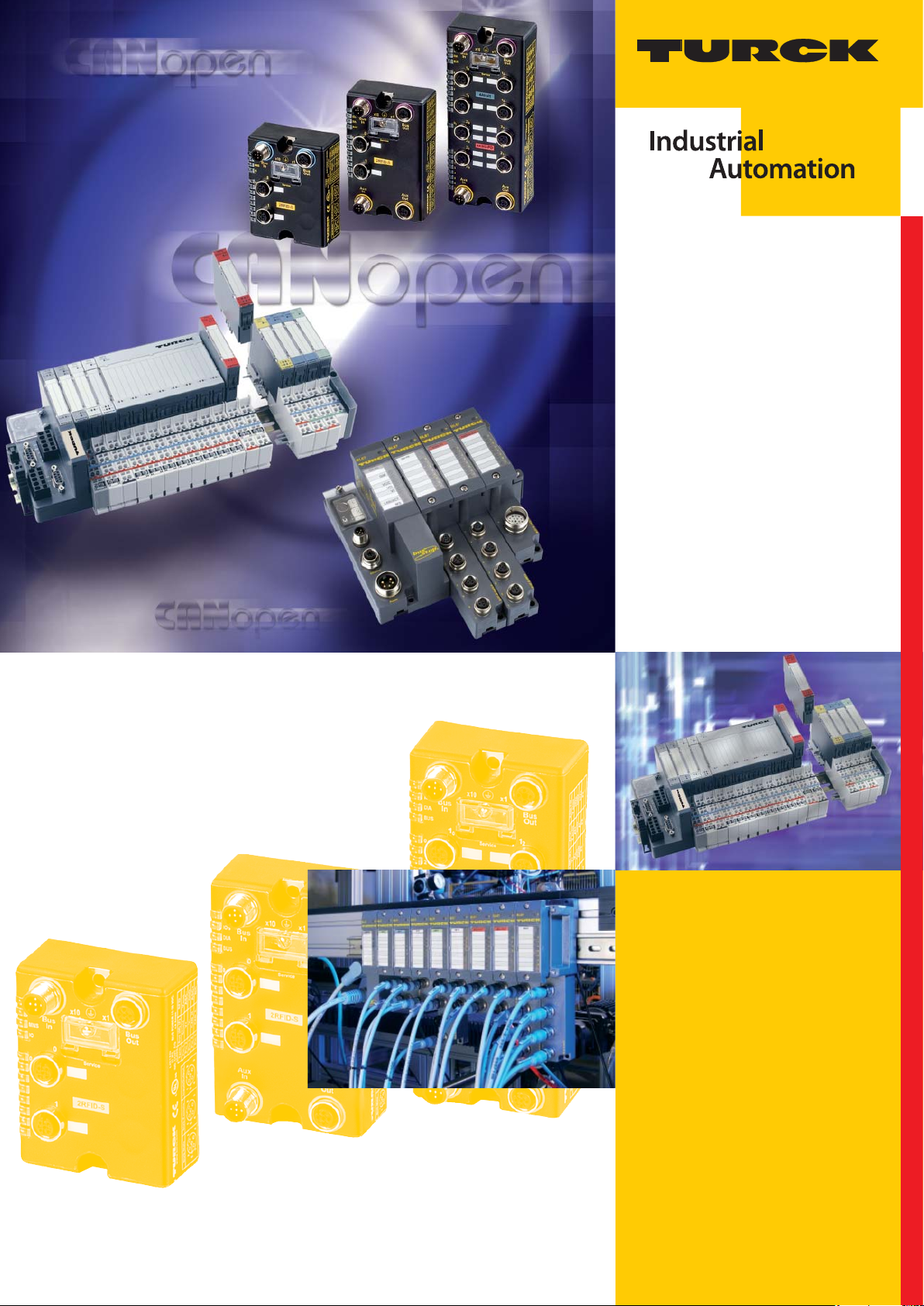
USER MANUAL
BLXX –
CANOPENOBJECT
REGISTER
Sense it! Connect it! Bus it! Solve it!
Page 2

All brand and product names are trademarks or registered trade marks of the owner
concerned.
Edition 0511
© Hans Turck GmbH, Muelheim an der Ruhr
All rights reserved, including those of the translation.
No part of this manual may be reproduced in any form (printed, photocopy, microfilm or any
other process) or processed, duplicated or distributed by means of electronic systems
without written permission of Hans Turck GmbH & Co. KG, Muelheim an der Ruhr.
Subject to alterations without notice
Page 3

Warning!
Before commencing the installation
Disconnect the power supply of the device.
Ensure that devices cannot be accidentally restarted.
Verify isolation from the supply.
Earth and short circuit.
Cover or enclose neighboring units that are live.
Follow the engineering instructions of the device concerned.
Only suitably qualified personnel in accordance with EN 50 110-1/-2 (VDE 0 105 Part 100) may
work on this device/system.
Before installation and before touching the device ensure that you are free of electrostatic
charge.
The functional earth (FE) must be connected to the protective earth (PE) or to the potential equal-
ization. The system installer is responsible for implementing this connection.
Connecting cables and signal lines should be installed so that inductive or capacitive interfer-
ence do not impair the automation functions.
Install automation devices and related operating elements in such a way that they are well
protected against unintentional operation.
Suitable safety hardware and software measures should be implemented for the I/O interface so
that a line or wire breakage on the signal side does not result in undefined states in the automation devices.
Ensure a reliable electrical isolation of the low voltage for the 24 volt supply. Only voltage
supplies which meet the requirements of IEC 60 364-4-41 or. HD 384.4.41 S2 (VDE 0100 part 410).
Deviations of the mains voltage from the rated value must not exceed the tolerance limits given
in the specifications, otherwise this may cause malfunction and dangerous operation.
Emergency stop devices complying with IEC/EN 60 204-1 must be effective in all operating
modes of the automation devices. Unlatching the emergency-stop devices must not cause
restart.
Devices that are designed for mounting in housings or control cabinets must only be operated
and controlled after they have been installed with the housing closed.
Measures should be taken to ensure the proper restart of programs interrupted after a voltage
dip or failure. This should not cause dangerous operating states even for a short time. If necessary, emergency-stop devices should be implemented.
Wherever faults in the automation system may cause damage to persons or property, external
measures must be implemented to ensure a safe operating state in the event of a fault or
malfunction (for example, by means of separate limit switches, mechanical interlocks etc.).
The electrical installation must be carried out in accordance with the relevant regulations (e. g.
with regard to cable cross sections, fuses, PE).
All work relating to transport, installation, commissioning and maintenance must only be carried
out by qualified personnel. (respect IEC 60 364 or HD 384 or DIN VDE 0100 and national work
safety regulations).
All shrouds and doors must be kept closed during operation.
Page 4

Page 5

Table of Contents
1About this manual
1.1 Documentation concept .................................................................................................................................1-2
1.1.1 Additional documentation .................................................................................................................................................................1-2
1.2 General ............................................................................................................................................................1-2
1.2.1 Prescribed use .........................................................................................................................................................................................1-2
1.2.2 Notes concerning planning/ installation of this product ........................................................................................................1-2
1.3 Description of symbols used ..........................................................................................................................1-3
2 CANopen
2.1 CANopen ..........................................................................................................................................................2-2
2.1.1 General.......................................................................................................................................................................................................2-2
2.1.2 Communication ...................................................................................................................................................................................... 2-2
2.2 EDS-file – Electronic data sheet......................................................................................................................2-5
2.3 BL×× and CANopen .........................................................................................................................................2-5
2.3.1 Setting up communication.................................................................................................................................................................2-5
2.3.2 Parameterization through Service Data Objects (SDO)......................................................................................................... 2-10
2.3.3 Transmission of Process Data Objects (PDO) ............................................................................................................................ 2-14
2.3.4 Inhibit Time............................................................................................................................................................................................ 2-16
2.3.5 Event Timer............................................................................................................................................................................................ 2-16
2.3.6 Mapping Objects in PDOs ................................................................................................................................................................ 2-16
2.3.7 Commands for "Parameter Save" and "Restore Defaults" .................................................................................................... 2-24
3 Object dictionary - overview of all objects
3.1 Overview of all objects....................................................................................................................................3-2
4 Device (gateway) objects
4.1 Objects of the Communication Profile (acc. to CiA DS-301)........................................................................4-2
4.1.1 Object 1000
4.1.2 Object 1001
4.1.3 Object 1005
4.1.4 Object 1008
4.1.5 Object 1009
4.1.6 Object 100A
4.1.7 Object 100C
4.1.8 Object 100D
4.1.9 Object 1010
4.1.10 Object 1011
4.1.11 Object 1014
4.1.12 Object 1016
4.1.13 Object 1017
4.1.14 Object 1018
4.1.15 Object 1020
4.1.16 Object 1027
4.2 Objects for the Transfer of Service Data ..................................................................................................... 4-20
4.2.1 Objects 1200
– Device Type ............................................................................................................................................................4-5
hex
– Error Register..........................................................................................................................................................4-5
hex
– SYNC COB-ID ..........................................................................................................................................................4-6
hex
– Device Name ..........................................................................................................................................................4-7
hex
– Manufacturer Hardware Version.....................................................................................................................4-8
hex
– Manufacturer Software Version ...................................................................................................................... 4-8
hex
– Guard Time .............................................................................................................................................................4-9
hex
– Lifetime Factor ......................................................................................................................................................4-9
hex
– Store Parameters ............................................................................................................................................... 4-10
hex
– Restore Default Parameters ........................................................................................................................... 4-11
hex
– Emcy COB-ID........................................................................................................................................................ 4-12
hex
– Consumer Heartbeat Time............................................................................................................................. 4-13
hex
– Producer Heartbeat Time ............................................................................................................................... 4-15
hex
– Identity Object .................................................................................................................................................... 4-16
hex
– Verify Configuration ......................................................................................................................................... 4-17
hex
– Module List........................................................................................................................................................... 4-19
hex
to 1203
hex
– Server SDO Default Parameters ............................................................................................ 4-20
hex
D301230 - BLxx- CANopen 0511
i
Page 6

4.3 Objects for the Transfer of Process Output Data ....................................................................................... 4-21
4.3.1 Object 1400
4.3.2 Object 1600
to 141F
hex
to 161F
hex
– Receive PDO Comm. Default Parameters.............................................................................4-21
hex
– Receive PDO-Mapping Parameter ..........................................................................................4-24
hex
4.4 Objects for the Transfer of Process Input Data .......................................................................................... 4-27
4.4.1 Object 1800
4.4.2 Objects 1A00
to 181F
hex
to 1A1F
hex
– Transmit PDO-Parameters .........................................................................................................4-27
hex
- Transmit PDO Mapping Parameter.......................................................................................4-30
hex
4.5 Objects for network management (not valid for BLCCO) .......................................................................... 4-33
4.5.1 Object 1F80
4.5.2 Object 1F81
4.5.3 Object 1F82
4.5.4 Object 1F83
– NMT Start-up .......................................................................................................................................................4-33
hex
– Slave Assignment ............................................................................................................................................... 4-34
hex
– Request NMT .......................................................................................................................................................4-36
hex
– Request Guarding ..............................................................................................................................................4-38
hex
4.6 Overview about the objects of the Device Profile (acc. to CiA DS-401 and 406) ..................................... 4-39
4.6.1 Object 67FF
4.6.2 Object 6FFF
– Device Type ..........................................................................................................................................................4-39
hex
– Device Type...........................................................................................................................................................4-40
hex
4.7 Manufacturer specific device objects.......................................................................................................... 4-40
4.7.1 Object 2000
4.7.2 Object 2010
4.7.3 Object 2400
4.7.4 Object 2401
– Serial Number...................................................................................................................................................... 4-40
hex
– Node ResetModifiers.........................................................................................................................................4-41
hex
- System Voltages (only BL67) ...........................................................................................................................4-45
hex
- System Currents (only BL67) ...........................................................................................................................4-45
hex
5 Objects for digital input modules
5.1 Digital input modules BL×× ........................................................................................................................... 5-2
5.2 General object overview for digital input modules ..................................................................................... 5-2
5.2.1 Object 6000
5.2.2 Object 6020
Object 6022
5.2.3 Object 6100
5.2.4 Object 6120
– Read Input 8 Bit..................................................................................................................................................... 5-4
hex
– Read Input Bit (1 to 128), Object 6021
hex
– Read Input Bit (257 to 288) ............................................................................................................................... 5-5
hex
– Read Input 16 Bit .................................................................................................................................................. 5-6
hex
– Read Input 32 Bit .................................................................................................................................................. 5-6
hex
– Read Input Bit (129 to 256),
hex
6 Objects for digital output modules
6.1 Digital output modules BL××......................................................................................................................... 6-2
6.2 General object overview for digital output modules .................................................................................. 6-3
6.2.1 Object 6200
6.2.2 Object 6206
6.2.3 Object 6207
6.2.4 Object 6220
Object 6222
6.2.5 Object 6250
Object 6252
6.2.6 Object 6260
Object 6262
6.2.7 Object 6300
6.2.8 Object 6306
6.2.9 Object 6307
6.2.10 Object 6320
6.2.11 Object 6326
6.2.12 Object 6327
– Write Output 8 Bit ................................................................................................................................................ 6-4
hex
– Error Mode Output 8 Bit .................................................................................................................................... 6-5
hex
– Error State Output 8 Bit ...................................................................................................................................... 6-6
hex
– Write Output Bit (1 to 128), Object 6221
hex
– Write Output Bit (257 to 288)........................................................................................................................... 6-7
hex
– Error Mode Output Bit (1 to 128), Object 6251
hex
– Error Mode Output Bit (257 to 288) ............................................................................................................... 6-8
hex
– Error State Output Bit (1 to 128), Object 6261
hex
– Error State Output Bit (257 to 288) ................................................................................................................ 6-9
hex
– Write Output 16 Bit............................................................................................................................................ 6-10
hex
– Error Mode Output 16 Bit ................................................................................................................................6-10
hex
– Error State Output 16 Bit .................................................................................................................................6-11
hex
– Write Output 32 Bit............................................................................................................................................ 6-12
hex
– Error Mode Output 32 Bit ................................................................................................................................6-13
hex
– Error State Output 32 Bit .................................................................................................................................6-14
hex
– Write Output Bit (129 to 256),
hex
– Error Mode Output Bit (129 to 256),
hex
– Error State Output Bit (129 to 256),
hex
D301230 - BLxx- CANopen 0511ii
Page 7

7 Objects for digital combi modules
7.1 Digital combi modules BL×× ..........................................................................................................................7-2
7.2 General object overview for digital combi modules ....................................................................................7-2
8 Objects for analog input modules
8.1 Analog input modules BL×× ...........................................................................................................................8-2
8.2 General object overview for analog input modules .....................................................................................8-2
8.2.1 Object 5420
8.2.2 Object 6401
8.2.3 Object 6421
8.2.4 Object 6422
8.2.5 Object 6423
8.2.6 Object 6424
8.2.7 Object 6425
8.2.8 Object 6426
8.2.9 Object 6427
8.2.10 Object 6428
– Manu Spec Analog Input Range......................................................................................................................8-3
hex
– Read Analog Input 16 Bit ................................................................................................................................ 8-10
hex
– Analog Input Interrupt Trigger Selection ............................................................................................... 8-11
hex
– Analog Input Interrupt Source...................................................................................................................... 8-13
hex
– Analog Input Global Interrupt Enable........................................................................................................ 8-14
hex
– Analog Input Interrupt Upper Limit Integer ............................................................................................ 8-14
hex
– Analog Input Interrupt Lower Limit Integer ............................................................................................ 8-15
hex
– Analog Input Interrupt Delta Unsigned .................................................................................................... 8-15
hex
– Analog Input Interrupt Negative Delta Unsigned ................................................................................. 8-16
hex
– Analog Input Interrupt Positive Delta Unsigned.................................................................................... 8-16
hex
9 Objects for analog output modules
9.1 Analog output modules BL×× ........................................................................................................................9-2
9.2 General object overview for analog output modules ..................................................................................9-2
9.2.1 Object 5440
9.2.2 Object 6411
9.2.3 Object 6443
9.2.4 Object 6444
– Manu Spec Analog Output Range.................................................................................................................. 9-4
hex
– Write Analog Output 16 Bit............................................................................................................................... 9-6
hex
- Analog Output Error Mode ................................................................................................................................9-7
hex
– Analog Output Error State................................................................................................................................. 9-8
hex
10 Objects for RS232/RS4xx modules
10.1 RS××× modules BL×× ................................................................................................................................... 10-2
10.2 Allgemeine Objektübersicht für RS232/RS4××-Module ...........................................................................10-2
10.2.1 Object 5600
10.2.2 Object 5601
10.2.3 Object 5602
– RS232/RS4xx Parameters ................................................................................................................................ 10-2
hex
– RS232/RS4xx RxD ............................................................................................................................................... 10-4
hex
– RS232/RS4xx TxD ............................................................................................................................................... 10-7
hex
11 Objects for Encoder modules (SSI, CNT)
11.1 Encoder module BL×× .................................................................................................................................. 11-4
11.2 General object overview for encoder modules .......................................................................................... 11-4
11.2.1 Object 5800
11.2.2 Object 5801
11.2.3 Object 5802
11.2.4 Object 5803
11.2.5 Objekt 5804
11.2.6 Object 5805
11.2.7 Object 5806
11.2.8 Object 5808
11.2.9 Object 5810
11.2.10 Object 5811
11.2.11 Object 5820
11.2.12 Object 5821
– Encoder Basic Mode ......................................................................................................................................... 11-6
hex
– Encoder Config ................................................................................................................................................... 11-7
hex
– Encoder Status.................................................................................................................................................. 11-11
hex
– Encoder Flags....................................................................................................................................................11-13
hex
– Encoder Diag.....................................................................................................................................................11-15
hex
– Encoder Native Status ....................................................................................................................................11-16
hex
– Optional Encoder Status ...............................................................................................................................11-18
hex
– Encoder Control ............................................................................................................................................... 11-19
hex
– Encoder Load Prepare Value .......................................................................................................................11-21
hex
– Encoder Pulse Width ......................................................................................................................................11-22
hex
– Measuring Integration Time ........................................................................................................................ 11-22
hex
– Measuring Low Limit ......................................................................................................................................11-23
hex
D301230 - BLxx- CANopen 0511
iii
Page 8

11.2.13 Object 5822
11.2.14 Object 5823
11.2.15 Object 5824
11.2.16 Object 5825
11.2.17 Object 5827
11.2.18 Object 5830
11.2.19 Object 5831
11.2.20 Object 5840
11.2.21 Object 5901
11.2.22 Object 5902
11.2.23 Object 5903
11.2.24 Object 5904
11.2.25 Object 5908
11.2.26 Object 5910
11.2.27 Object 5913
11.2.28 Object 5920
11.2.29 Object 5931
11.2.30 Object 6800
11.2.31 Objekt 6810
11.2.32 Object 6820
11.2.33 Object 6B00
11.2.34 Object 6B01
11.2.35 Object 6B02
11.2.36 Object 6B10
11.2.37 Object 6B20
11.2.38 Object 6B30
11.2.39 Object 6C00
11.2.40 Object 6C01
11.2.41 Object 6C02
11.2.42 Object 6D00
Measuring step (linear), Object 6D02
11.2.43 Object 6FFF
– Measuring High Limit .................................................................................................................................... 11-25
hex
– Measuring Units Per Revolution ................................................................................................................ 11-25
hex
– Measuring Divisor ........................................................................................................................................... 11-26
hex
– Measuring Factor ............................................................................................................................................ 11-27
hex
– Measuring Timeout ........................................................................................................................................ 11-27
hex
– Measuring Value .............................................................................................................................................. 11-28
hex
– Encoder Latch Value....................................................................................................................................... 11-29
hex
– Diag Mapping................................................................................................................................................... 11-29
hex
– PWM Config.......................................................................................................................................................11-31
hex
– PWM Status ....................................................................................................................................................... 11-33
hex
– PWM Flags ......................................................................................................................................................... 11-34
hex
– PWM Diag........................................................................................................................................................... 11-35
hex
– PWM Control..................................................................................................................................................... 11-36
hex
– PWM Load Prepare Value............................................................................................................................. 11-38
hex
– PWM Duty Cycle .............................................................................................................................................. 11-39
hex
– PWM Period Duration .................................................................................................................................... 11-39
hex
– PWM Latch Value............................................................................................................................................. 11-40
hex
– Operating Parameters ................................................................................................................................. 11-40
hex
– Preset Values for Multi-Sensor Devices ................................................................................................... 11-41
hex
– Position Value................................................................................................................................................... 11-42
hex
– CAM State Register ......................................................................................................................................... 11-42
hex
– CAM1 Enable Register ................................................................................................................................... 11-44
hex
– CAM Polarity Register .................................................................................................................................... 11-45
hex
– CAM1 Low Limit .............................................................................................................................................. 11-46
hex
– CAM1 High Limit ............................................................................................................................................. 11-47
hex
– CAM1 Hysteresis.............................................................................................................................................. 11-48
hex
– Area State Register ......................................................................................................................................... 11-49
hex
– Work Area Low Limit...................................................................................................................................... 11-50
hex
– Work Area High Limit .................................................................................................................................... 11-51
hex
– Operating Status, Object 6D01
hex
– Device Type ....................................................................................................................................................... 11-52
hex
– Number of Distinguishable Revolutions ............................................... 11-52
hex
– SingleTurn Resolution (rotary),
hex
11.3 Process output/ control interface of the Encoder modules.....................................................................11-52
11.3.1 Meaning of the process output bits of BL××-1SSI .................................................................................11-52
11.3.2 Meaning of the process output bits of BL20-1CNT-24VDC ............................................................................................... 11-53
11.3.3 Meaning of the process output bits of BL20-E-2CNT-2PWM ............................................................................................ 11-56
11.3.4 Meaning of the process output bits of BL67-1CNT/ENC .................................................................................................... 11-58
11.4 Meaning of the process input bits of the Encoder modules....................................................................11-59
11.4.1 Meaning of the process input bits of BL××-1SSI ...................................................................................11-59
11.4.2 Meaning of the process input bits of BL20-1CNT-24VDC .................................................................................................. 11-61
11.4.3 Meaning of the process input bits of BL20-E-2CNT-2PWM ............................................................................................... 11-63
11.4.4 Meaning of the process input bits of BL67-1CNT/ENC ....................................................................................................... 11-66
11.5 Parameter interface of the Encoder modules........................................................................................... 11-67
11.5.1 Meaning of the parameter bits of BL××-1SSI ........................................................................................11-67
11.5.2 Meaning of the parameter bits of BL20-1CNT-24VDC......................................................................................................... 11-69
11.5.3 Meaning of the parameter bits of BL20-E-2CNT-2PWM ..................................................................................................... 11-71
11.5.4 Meaning of the parameter bits of BL67-1CNT/ENC.............................................................................................................. 11-74
11.6 Diagnostic interface of the Encoder modules .......................................................................................... 11-76
11.6.1 Meaning of the diagnostic bits of BL××-1SSI ........................................................................................11-76
11.6.2 Meaning of the diagnostic bits of BL20-1CNT-24VDC......................................................................................................... 11-77
11.6.3 Meaning of the diagnostic bits of BL20-E-2CNT-2PWM ..................................................................................................... 11-78
11.6.4 Meaning of the diagnostic bits of BL67-1CNT/ENC.............................................................................................................. 11-79
D301230 - BLxx- CANopen 0511iv
Page 9

12 Objects for SWIRE modules
12.1 Motor starter modules BL20 ........................................................................................................................ 12-2
12.2 General object overview for SWIRE modules ............................................................................................. 12-2
12.2.1 Representation of process input data.......................................................................................................................................... 12-3
12.2.2 Representation of process output data ...................................................................................................................................... 12-4
12.2.3 Representation of diagnostic data................................................................................................................................................ 12-6
12.2.4 Representation of parameter data.............................................................................................................................................. 12-10
13 Objects for RFID-modules
13.1 RFID-S-module BL20 .................................................................................................................................... 13-2
13.2 General object overview for RFID-S-modules ............................................................................................ 13-2
13.3 Object 5700
13.4 Object 5701
13.5 Object 5702
13.6 Object 5703
13.7 Object 5708
13.8 Object 5722
- 8 byte process input data................................................................................................. 13-2
hex
- 12 byte process input data............................................................................................... 13-3
hex
- 8 byte process output data .............................................................................................. 13-3
hex
- 12 byte process output data ............................................................................................ 13-4
hex
- 1 byte status messages..................................................................................................... 13-4
hex
- 1 byte parameter .............................................................................................................. 13-5
hex
14 Manufacturer specific objects
14.1 General .......................................................................................................................................................... 14-2
14.1.1 Module related manufacturer specific objects......................................................................................................................... 14-2
14.1.2 Slot-related manufacturer specific objects ................................................................................................................................ 14-4
14.1.3 Process input objects ......................................................................................................................................................................... 14-5
14.1.4 Process output objects ...................................................................................................................................................................... 14-6
14.1.5 Diagnosis objects ................................................................................................................................................................................ 14-8
14.1.6 Parameter objects ............................................................................................................................................................................... 14-9
15 Diagnostics - Emergency Frames
15.1 General .......................................................................................................................................................... 15-2
15.2 Structure of the emergency frames ............................................................................................................ 15-2
15.2.1 Emergency Error-Codes .................................................................................................................................................................... 15-2
15.2.2 Error register.......................................................................................................................................................................................... 15-4
15.3 Emergency codes for module diagnostics.................................................................................................. 15-5
15.3.1 General module error codes............................................................................................................................................................ 15-5
15.3.2 Digital output modules .................................................................................................................................................................... 15-5
15.3.3 Analog Input Modules ....................................................................................................................................................................... 15-6
15.3.4 Technology modules ......................................................................................................................................................................... 15-8
16 Index
D301230 - BLxx- CANopen 0511
v
Page 10

D301230 - BLxx- CANopen 0511vi
Page 11

1 About this manual
1.1 Documentation concept.................................................................................................................... 2
1.1.1 Additional documentation ....................................................................................................................2
– BL67 ..................................................................................................................................................2
– BL20 ..................................................................................................................................................2
– BLC....................................................................................................................................................2
1.2 General ............................................................................................................................................. 2
1.2.1 Prescribed use.............................. ... .... ...................................... .... ... ... ... ..............................................2
1.2.2 Notes concerning planning/ installation of this product.......................................................................2
1.3 Description of symbols used ............................................................................................................ 3
D301230 - BLxx- CANopen 0511 1-1
Page 12
About this manual
1.1 Documentation concept
This manual describes the CANopen object directory for TURCK BLxx-products.
If not marked especially, the object descriptions are valid for all products of the product lines BL20, BL67
and BLcompact.
1.1.1 Additional documentation
BL67
D301006 - BL67 – User manual for CANopen
Data sheets for the BL20-products www.turck.com
BL20
D301108 BL20 – ECO gateway for CANopen
D301109 - BL20 – User manual for CANopen
Data sheets for the BL20-products www.turck.com
BLC
Manuals and data sheets for the BLC-CANopen-products www.turck.com
1.2 General
Attention
Please read this section carefully. Safety aspects cannot be left to chance when dealing with
electrical equipment.
1.2.1 Prescribed use
Appropriate transport, storage, deployment and mounting as well as careful operating and thorough
maintenance guarantee the trouble-free and safe operation of these devices.
Danger
The devices described in this manual must be used only in applications prescribed in this
manual or in the respective technical descriptions, and only with certified components and
devices from third party manufacturers.
1.2.2 Notes concerning planning/ installation of this product
Danger
All respective safety measures and accident protection guidelines must be considered carefully and without exception.
D301230 - BLxx- CANopen 05111-2
Page 13

Description of symbols used
1.3 Description of symbols used
Danger
This sign can be found next to all notes that indicate a source of hazards. This can refer to danger to personnel or damage to the system (hardware and software) and to the facility.
This sign means for the operator: work with extreme caution.
Attention
This sign can be found next to all notes that indicate a potential hazard.
This can refer to possible danger to personnel and damages to the system (hardware and software) and to the facility.
Note
This sign can be found next to all general notes that supply important information about one
or more operating steps.
These specific notes are intended to make operation easier and avoid unnecessary work due
to incorrect operation.
D301230 - BLxx- CANopen 0511
1-3
Page 14

About this manual
D301230 - BLxx- CANopen 05111-4
Page 15

2CANopen
2.1 CANopen ........................................................................................................................................... 2
2.1.1 General .................................................................................................................................................2
2.1.2 Communication ....................................................................................................................................2
– Network Management Messages......................................................................................................2
– Service Data Objects (SDOs).............................................................................................................3
– Process Data Objects (PDOs) ...........................................................................................................3
– Special Function Objects ..................................................................................................................4
2.2 EDS-file – Electronic data sheet......................................................................................................... 5
2.3 BL×× and CANopen ........................................................................................................................... 5
2.3.1 Setting up communication ...................................................................................................................5
– Minimum Boot-up..............................................................................................................................5
– Identifier for the Standard Objects ................................................................... ... .... ... .......................8
– Set up Node Guarding Protocol........................................................................................................9
– Boot-up Message............................................................................................................................10
2.3.2 Parameterization through Service Data Objects (SDO)......................................................................10
– Write (Write to Object Dictionary) ...................................................................................................12
– Parameter Storing/Restoring..................................... .... ... ....................................... ... ... ... ... ............13
2.3.3 Transmission of Process Data Objects (PDO)....................................................................................14
– Communication parameter COB-ID ................................................................................................14
– Transmission Type .................... ... .... ... ... ... ....................................... ... ... .... ... ... ...............................15
2.3.4 Inhibit Time.........................................................................................................................................16
2.3.5 Event Timer.........................................................................................................................................16
– Available PDOs............. ... ....................................... ... .... ... ... ....................................... ... .. ................16
2.3.6 Mapping Objects in PDOs..................................................................................................................16
– Default-PDOs and PDO-mappings..................................................................................................17
– BL××-spezifische Default-PDOs (gilt nicht für BL compact)...........................................................18
– Mappable Objects ...........................................................................................................................22
– Procedure for Altering PDO-Mappings ...........................................................................................23
2.3.7 Commands for "Parameter Save" and "Restore Defaul ts " ........................................ ... ... ... ...............24
D301230 - BLxx- CANopen 0511 2-1
Page 16

CANopen
2.1 CANopen
2.1.1 General
CANopen is an open, non-proprietary network protocol. It consists of a profile family, based on a
communication profile and several device profiles. The CANopen communication profile is
standardized as CiA DS-301 (Application Layer and Communication Profile).
The CANopen device profile for I/O-modules has been published as CiA DS-401 (Device Profile for I/OModules).
CANopen is based on the following standards:
ISO 11 898 (Physical and Data Link Layer)Layers 1 and 2 of the ISO/OSI communication model
CiA DS-301 (Application Layer and Communication Profile) CANopen communication profile
Note
The following description of CANopen is an excerpt from the homepage of CiA (CAN in
Automation), the international users’ and manufacturers’ organization for CAN.
CiA DS-302 (Framework for Programmable CANopen Devices) CANopen Network Management
NMT
CiA DS-401 (Device Profile for I/O-modules)
CiA DS-406 (Device Profile for Encoders) CANopen device profile for counter modules
CiA DS-102 (CAN Physical Layer for Industrial Applications) General application in the field sector
(connectors and bit rates) on the basis of ISO 11898
2.1.2 Communication
The lower layers of CANopen are defined according to the ISO-OSI model in the ISO 11898 standard.
Communication between the individual nodes is made by transmitting "Telegrams".
4 different types of telegram message are defined for CANopen:
Network management messages
Service data objects SDO
Process data objects PDO
Predefined messages
Network Management Messages
Network management messages are used in the network to control the nodes and their operating
states. This type of message makes it possible, for instance, to configure the data transmission
mechanism of a node.
The Network Management objects include Boot-up message, Heartbeat protocol and NMT message.
Boot-up message, Heartbeat and Node Guarding are implemented as single CAN frames with 1-byte
data field.
The NMT message is mapped to a single CAN frame with a data length of 2 byte. The CAN-Identifier
is 0. The first byte contains the command specifier and the second contains the Node-ID of the device
that must perform the command (in the case of Node-ID 0 all nodes have to perform the command).
The NMT message transmitted by the NMT master forces the nodes to transit to another NMT state.
CANopen defines the following statsus: "Initialization", "Pre-Operational", "Operational" and "Stopped".
D301230 - BLxx- CANopen 05112-2
Page 17

CANopen
After a "power-on", each CANopen devices is in the status "Initialization" and automatically changes to
the Pre-Operational status . In this state the transmission of SDOs is allowed. If the NMT master has
set one or more nodes into the state Operational, they are allowed to transmit and to receive PDOs. In
the state Stopped no communication is allowed except that of NMT objects.
The state Initialization is devided into 3 sub-states. in order to enable a complete or partial reset of a
node. In the sub-state Reset Application the parameters of the manufacturer-specific profile area and
the standardized device profile area are set to their power-on values. In the sub-state Reset
Communication the parameters of the communication profile area are set to their power-on values.
The third sub-state is initializing, which a node enters automatically after power-on. Power-on values
are the last stored parameters.
The Heartbeat protocol and Node Guarding (see Set up Node Guarding Protocol (page 2-9)) are for
error control purposes and signals the presence of a node and its state. The Heartbeat message is a
periodic message of the node to one or several other nodes. It indicates that the sending node is still
working properly.
A device sends the Boot-up message to indicate to the NMT master that it has changed from
„Initialization“ tot he state Pre-operational. This occurs whenever the device initially boots-up but also
after a power-out during operation. The Boot-up message has the same identifier as the Heartbeat
object, however, its data content is zero.
Service Data Objects (SDOs)
A Service Data Object (SDO) reads from entries or writes to entries of the Object Dictionary.
The SDO transport protocol allows transmitting objects of any size. The first byte of the first segment
contains the necessary flow control information including a toggle bit to overcome the problem of
doubly received CAN frames. The next three bytes of the first segment contain index and sub-index of
the Object Dictionary entry to be read or written. The last four bytes of the first segment are available
for user data. The second and the following segments (using the very same CAN identifier) contain the
control byte and up to seven bytes of user data. The receiver confirms each segment or a block of
segments, so that a peer-to-peer communication (client/server) takes place.
Process Data Objects (PDOs)
Process Data Objects (PDOs) are mapped to a single CAN frame using up to 8 bytes of the data field to
transmit application objects. Each PDO has a unique identifier and is transmitted by only one node, but
it can be received by more than one (producer/consumer communication). PDO transmissions may be
dr iven by an inte rnal ev ent, by an internal timer, by remote requests and by t he Sync mes sage r ece ive d:
PDO transmissions
„Event-“ or „timer-driven“:
An event (specified in the device profile) triggers message transmission. An elapsed timer
additionally triggers the periodically transmitting of PDO-messages, even if no event has ocurred.
Remotely requested (RTR):
Another device may initiate the transmission of an asynchronous PDO by sending a remote
transmission request (remote frame).
Sync Master (Synchronous transmission:)
In order to initiate simultaneous sampling of input values of all nodes, a periodically transmitted
Sync message is required. Synchronous transmission of PDOs takes place in cyclic and acyclic
transmission mode. Cyclic transmission means that the node waits for the Sync message, after
which it sends its measured values. Acyclically transmitted synchronous PDOs are triggered by a
defined application-specific event. The device transmits it's input values. Further transmission is
only done if a further Sync messages occurs.
D301230 - BLxx- CANopen 0511
2-3
Page 18

CANopen
Special Function Objects
CANopen also defines three specific protocols for synchronization, emergency indication, and timestamp transmission.
Synchronization object (Sync)
The Sync Object is broadcast periodically by the Sync Producer. This object is a central timer. The
Sync Object is broadcast periodically by the Sync Producer. The time period between Sync
messages is defined by the Communication Cycle Period, which may be reset by a configuration
tool to the application devices during the boot-up process. There can be a time jitter in transmission
by the Sync Producer due to some other objects with higher prior identifiers or by one frame being
transmitted just before the Sync message. The Sync message is mapped to a single CAN frame with
the identifier 128 by default.
Emergency object (Emcy)
The Emergency message is triggered by the occurrence of a device internal error situation and are
transmitted from an Emergency producer on the concerned application device. This makes them
suitable for interrupt type error alerts. An Emergency message is transmitted only once per ‘error
event’. As long as no new errors occurs on a device, no further Emergency message can be
transmitted. Zero or more Emergency consumers may receive these. The reaction of the Emergency
consumer is application-specific. CANopen defines several Emergency Error Codes to be
transmitted in the Emergency message, which is a single CAN frame with 8 data byte.
Time stamp object (Time)
By means of Time-Stamp, a common time frame reference is provided to application devices. It
contains a value of the type Time-of-Day. This object transmission follows the producer/consumer
push model. The associated CAN frame has the pre-defined identifier 256 and a data field of 6-byte
length.
D301230 - BLxx- CANopen 05112-4
Page 19
EDS-file – Electronic data sheet
1
3
4
2
5
6
7
8
9
10
11
12
13
14
P
ower on or hardware reset
Pre-Operational state
Initialization state
Operational state
Stopped state
2.2 EDS-file – Electronic data sheet
CANopen nodes are embedded in the CANopen structure by the help of a standardized EDS file
(Electronic Data Sheet).
The EDS file lists all necessary Objects with their corresponding Sub-indices and the matching entries.
The latest version of a particular EDS file can be downloaded directly from the TURCK homepage
www.turck.com.
2.3 BL×× and CANopen
BL×× supports the following CANopen-functions:
SDO transfer, any length of information
Emergency object
Sync frame evaluation
Event-driven PDOs
Synchronous PDOs (clock-synchronous)
Remote-requested PDO/polling
2.3.1 Setting up communication
Minimum Boot-up
BL×× supports the Minimum Boot-up function described in CiA DS-301.
Table 1:
Meaning of the
abbreviations
Figure1:
Boot procedure
with Minimum
Boot-up
Abbreviation Meaning Description
cs NMT command specifier A designation label for the required service
Node-ID Node Identifier Identifier for the node; an identification byte that is
Booting with the Minimum Boot-up function is the typical application option for CANopen, and runs
according to the following state diagram:
set through the DIP switches for the CAN node.
D301230 - BLxx- CANopen 0511
2-5
Page 20

CANopen
Byte 0
Master
Slave
COB-ID = 0
Byte 1
Node-
ID
cs = 1
Byte 0
Master
Slave
COB-ID = 0
Byte 1
Node-
ID
cs = 1
1 Power-on (automatic change of state to the "Initialization" condition)
2 Initialization Finished (automatic change of state to "Pre-Operational")
3 Start Remote Node (start the CAN node)
4 Enter Pre-Operational (change over to "Pre-Operational")
5 Stop Remote Node (stop the CAN node)
6 Start Remote Node (start the CAN node)
7 Enter Pre-Operational (change over to "Pre-Operational")
8 Stop Remote Node (stop the CAN node)
9 Reset Node (reset the complete CAN node)
10 Reset Node (reset the complete CAN node)
11 Reset Node (reset the complete CAN node)
12 Reset Communication (reset communication for the CAN node)
13 Reset Communication (reset communication for the CAN node)
14 Reset Communication (reset communication for the CAN node)
The following messages are exchanged in the states mentioned:
Operational: PDO and SDO communication
Pre-Operational: only SDO-communication
The services listed above (1 to 14) are required by CANopen or performed independently by the nodes
in order to change from one state to another.
The "Stopped" state can be skipped when using Minimum Boot-up.
1 Power-on (automatic change of state to the "Initialization" condition)
2 Initialization finished (automatic change of state to "Pre-Operational")
3, 6 Start Remote Node (start the CAN node)
The internal change of state of the CANopen slave now requires a pause of at least 20 ms, before
another request may be made by the master.
D301230 - BLxx- CANopen 05112-6
Page 21

BL×× and CANopen
Byte 0
Master
Slave
COB-ID = 0
Byte 1
Node-
ID
cs = 128
Byte 0
Master
Slave
COB-ID = 0
Byte 1
Node-
ID
cs = 128
Byte 0
Master
Slave
COB-ID = 0
Byte 1
Node-
ID
cs = 2
Byte 0
Master
Slave
COB-ID = 0
Byte 1
Node-
ID
cs = 129
Byte 0
Master
Slave
COB-ID = 0
Byte 1
Node-
ID
cs = 130
15, 7 Enter Pre-Operational (change over to "Pre-Operational")
The internal change of state of the CANopen slave now requires a pause of at least 20 ms, before
another request may be made by the master.
15, 8 Stop Remote Node (stop the CAN node)
The internal change of state of the CANopen slave now requires a pause of at least 20 ms, before
another request may be made by the master.
15, 10, 11 Reset Node (reset the complete CAN node)
The execution of this command is confirmed by a boot-up message. This is in the form of a guard frame
with the data contents 00
hex
.
15, 13, 14 Reset Communication (reset communication for the CAN node)
The execution of this command is confirmed by a boot-up message. This is in the form of a guard frame
with the data contents 00
D301230 - BLxx- CANopen 0511
hex
.
2-7
Page 22

CANopen
Identifier for the Standard Objects
Node-ID
The identifier for each device in a CANopen network is the Node-ID. he CANopen slaves can be assigned
the Node-IDs 1 to 127. The maximum number of Node-IDs to be set may vary depending on the BLxxproduct.
COB-ID (Communication Object Identifier)
The identifier for each communication object in a CANopen network is the COB-ID. The COB-IDs for the
standard objects (digital input, digital output, analog input, analog output) are assigned automatically.
The ranges for the COB-IDs are defined by the "Predefined Master-Slave Connection Set".
Each range for the COB-IDs has 127 numerical values.
The COB-IDs are calculated according to the following rule:
COB-ID = Base-ID + Node-ID
Base-ID: 128; 384; 512; 640; 768; 896; 1024; 1152; 1280; 1408; 1536; 1792
Node-ID: max. 1 to 127
Table 2:
Identifiers for
basic objects
COB-ID Function Application
dec.
0000
01 to 127 001
128 080
129 to 255 081
256 100
257 to 384 101
385 to 511 181
512 200
513 to 639 201
640 280
641 to 767 281
768 300
769 to 895 301
hex
.
hex
to 07F
hex
hex
to 0FF
hex
hex
to 180
hex
to 1FF
hex
hex
to 27F
hex
hex
to 2FF
hex
hex
to 37F
hex
Network Management (NMT) Broadcast object
free
hex
Synchronization (Sync) Broadcast object
Emergency Message
hex
Timestamp Broadcast object
free
hex
Transmit PDO 1 Digital input
hex
free
Receive PDO 1 Digital output
hex
free
Transmit PDO 2 Analog input
hex
free
Receive PDO 2 Analog output
hex
896 380
897 to 1023 381
1024 400
1025 to 1151 401
1152 480
1153 to 1279 481
1280 500
hex
to 3FF
hex
hex
to 47F
hex
hex
to 4FF
hex
hex
free
Transmit PDO 3 Analog input
hex
free
Receive PDO 3 Analog output
hex
free
Transmit PDO 4 Analog input
hex
free
D301230 - BLxx- CANopen 05112-8
Page 23
BL×× and CANopen
Table 2:
Identifiers for
basic objects
COB-ID Function Application
dec.
1281 to 1407 501
1408 580
1409 to 1535 581
1536 600
1537 to 1663 601
1664 to 1772 680
1793 to 1919 701
hex
.
to 57F
hex
hex
to 5FF
hex
hex
to 67F
hex
to 6EC
hex
to 77F
hex
Receive PDO 4 Analog output
hex
free
Transmit SDO
hex
free
Receive SDO
hex
free
hex
NMT Error (Node Guarding, Heartbeat,
hex
Boot-Up)
1920 to 2014 800
2015 to 2031 7DF
7DE
7EF
hex
hex
hex
hex
to
to
free
NMT, LMT, DBT
Set up Node Guarding Protocol
Note
Further information on Node Guarding can be found in CiA DS-301.
Node Guarding is the name for the monitoring of network nodes by a network manager. You
distinguish between active and passive Node Guarding.
In addition, the CANopen network nodes check that their network manager is operating correctly and
that the network is functioning reliably.
In the default state, Node Guarding is inactive.
Active Node Guarding
To activate the Node Guarding protocol for a node, various parameters must be set for the Object
Dictionary:
[100C] = Guard time
Given in milliseconds; the query interval (polling) that is to be expected by the network slave.
Default = 0
[100D] = Lifetime factor
This factor, multiplied by the Guard time, is the time that should elapse after a Node Guarding
protocol error before the network slave generates an error message via EMCY. In this way, a
temporary communication problem, such as may be caused by heavy bus loading, can be bridged
without a Guarding Error.
Default = 0
Guard-ID
This is fixed and cannot be changed.
Guarding is initiated with the first Guard-Remote frame (Guarding-RTR) from the CANopen network
manager.
D301230 - BLxx- CANopen 0511
2-9
Page 24

CANopen
The Guarding Frame of the network manager has the COBID "1793 - 1 + Node-ID" and does not have a
data field.
Furthermore, the RTR bit in the message header must be set and the Data Length code = 1.
The node answers the telegram sent out by the network manager within the preset time (Guard time)
in the "Operational" state, with the data contents 5. The gateway answers the next polling query with
the contents 133. The following response from the gateway is with 5 again, and so on. This means that
the gateway changes the state of the most significant bit after every query (i.e. the bit is toggled). If the
node is in the "Pre-Operational" state, then the value of the data contents of the response telegram
toggles between 127 and 255. If the node is in the "Stop" state, the value toggles between 4 and 132.
If there is no query from the network manager within the preset time, then the gateway changes to the
state "Guard Fail". If output modules are fitted in the BL×× station, then their outputs will be put into
defined states, depending on the objects "Error mode output" and "Error state output" , or w ill re tai n the
last state that was received. Any RxPDOs that are received will still be processed and output again. If the
Guarding starts up again, the gateway leaves the "Guard Fail" state, but remains in the Pre-Operational
state. A "Start Node" command must be generated by the network manager in order to restart the
gateway (see CiA DS-301).
Passive Node Guarding
If a Guard-Time = 0 is set (see Object 100Chex – Guard Time (page 4-9)), than, passive guarding is
activated. This means that the gateway answers the Guard-Remote-Frames without itself starting a
Guard-Timer. The gateway does not change to the Pre-Operational state.
As an alternative to Node-/Life-Guarding, the Heartbeat mechanism (see Object 1016hex – Consumer
Heartbeat Time (page 4-13) and Object 1017hex – Producer Heartbeat Time (page 4-15)) newly
introduced with DS301 V4.0 is supported, which, unlike Guarding, does not require Remote frames.
Boot-up Message
After initialization (after Power-On, Reset-Node and Reset-Communication), a Boot-up message as per
CiA DS-301 V4.0 is sent out. This is in the form of a guard frame with the contents 00
Under certain circumstances, a network manager may fail to detect a short drop-out of an BL20
gateway (for example, as a result of voltage variations). This could occur under the following conditions:
The drop-out and initialization of the gateway happen in the time between two Guarding-Frames
The gateway was already in the Pre-Operational state beforehand
The last state of the toggle bit was 1
If a Boot-up message is sent out after a reset or initialization, then the drop-out mentioned above will
also not be missed by the network manager.
2.3.2 Parameterization through Service Data Objects (SDO)
SDO (= Service Data Object) is a confirmed CANopen service that is primarily used for parameterization
and configuration of the CANopen slaves (BL××) and less frequently for transmitting process data.
"Confirmed" means that an BL××-CANopen gateway (SDO server) that is addressed by this procedure
must acknowledge it through a response. In this way, the SDO client obtains information about
whether the BL×× gateway that it addressed was contacted, and whether the access was achieved
without any errors (error code in the response from the SDO server). SDO access means that the
contents of the Object Dictionary entries for an SDO server can be read or written, and that the settings
for a BL×× station can be made in this way.
hex
.
Four parallel SDO servers are supported. There are three "additional" SDOs, as well as the default SDO.
As a default, these are inactive, but can be parameterized and enabled through the Object Dictionary
entries 1201
to 1203
hex
hex
.
D301230 - BLxx- CANopen 05112-10
Page 25
BL×× and CANopen
0000
Byte 0
Byte 0
Byte 4
Byte 4
Byte 2
Byte 2
Byte 6
Byte 6
Byte 1
Byte 1
Byte 5
Byte 5
Byte 3
Byte 3
Byte 7
Byte 7
CCS =
40h
SCS =
4xh
Index
lsb msb
Index
lsb msb
Sub-Index
Sub-Index Data
COB-ID = 1537 + Node-ID - 1
COB-ID = 1409 + Node-ID - 1
Client
Client
Server
The communication parameters for the default SDO follow the Predefined Connection Set, and cannot
be modified (see CiA DS-301, V4.01).
In the following representations of the messages, the identifier of the CANopen message that is to be
sent can be found below the frame, and the contents of the data byte to be transmitted are within the
frame.
The following representations use the Expedited SDO Transfer, i.e. a maximum of 4 bytes of user data
can be transferred within one telegram.
Read (Read from Object Dictionary)
Figure2:
Read (Read from
Object Dictionary)
Note
CANopen also offers the possibility of segmented SDO-transfer of data with data length of
more than 4 bytes.
x... depending on the length of data read
LSB= Least Significant byte ? lowest value byte
MSB= Most Significant byte ? highest value byte
SCS = Server Command Specifier
CCS = Client Command Specifier
(see CiA DS-301)
The stated COB-ID refers to the default SDO server.
D301230 - BLxx- CANopen 0511
Note
The information in byte 0 "SCS " can optionally contain the length information for the
transmitted data bytes (see CiA DS-301, Page 9-21 ff). The information in byte 0 "SCS = 4x
means that no length information is present.
hex
2-11
“
Page 26
CANopen
Byte 0
Byte 0
Byte 4
Byte 4
Byte 2
Byte 2
Byte 6
Byte 6
Byte 1
Byte 1
Byte 5
Byte 5
Byte 3
Byte 3
Byte 7
Byte 7
Index
lsb msb
Index
lsb msb
Sub-Index
Sub-Index reserved
COB-ID = 1537 + Node-ID - 1
COB-ID = 1409 + Node-ID - 1
Client
Client
Server
Data
CCS =
2xh
SCS =
60h
Figure3:
Write
(Write to Object
Dictionary)
Write (Write to Object Dictionary)
LSB= Least Significant byte ? lowest value byte
MSB= Most Significant byte ? highest value byte
SCS = Server Command Specifier
Table 3:
Abort codes for
errors in SDO
transfer
CCS = Client Command Specifier
(see CiA DS-301)
The stated COB-ID refers to the default SDO server.
Note
The information in byte 0 "SCS " can optionally contain the length information for the
transmitted data bytes (see CiA DS-301). The information in byte 0 „SCS = 60h“ means that
no length information is present.
Attention
If an incorrect data length is given, the error code "Abort SDO Transfer Service" will be
generated (see CiA DS-301).
Abort code Description
0503 0000
0504 0001
hex
hex
Toggle bit not altered.
Client server command specifier not valid or unknown.
0601 0000
0601 0001
0601 0002
0602 0000
06040041
06040042
hex
hex
hex
hex
hex
hex
Unsupported access to an object.
Attempt to write a read only object.
Attempt to read a write only object.
Object does not exist in the object dictionary.
Object cannot be mapped to the PDO.
The number and length of objects exceeds PDO length.
D301230 - BLxx- CANopen 05112-12
Page 27
BL×× and CANopen
Byte 0
Byte 0
Byte 4
Byte 4
Byte 2
Byte 2
Byte 6
Byte 6
Byte 1
Byte 1
Byte 5
Byte 5
Byte 3
Byte 3
Byte 7
Byte 7
COB-ID = 1537 + Node-ID - 1
COB-ID = 1409 + Node-ID - 1
Client
Client
Server
22h
60h 1400h
1400h
1h
1h reserved
258h
Table 3:
Abort codes for
errors in SDO
transfer
Abort code Description
06040043
06040047
06070010
0607 0012
0607 0013
06090011
06090030
06090031
06090032
06090036
08000000
08000020
hex
hex
hex
hex
hex
hex
hex
hex
hex
hex
hex
hex
General parameter incompatibility reason.
General internal incompatibility in the device.
Data type does not match - wrong length.
Data type does not match- length too high.
Data type does not match- length too low.
Sub-index does not exist.
Value range of parameter exceeded.
Value range of parameter written too high.
Value range of parameter written too low
Maximum value is less than minimum value.
Other error
Data cannot be stored to the application.
Figure4:
Example COB-ID
08000021
08000022
Example:
Write a new COB-ID for RxPDO 1 (ID = 258
Parameter Storing/Restoring
Saving of communication and application parameters is executed by a command. This means that the
parameters transferred through an SDO are held in volatile memory, until they are saved by using the
command "Store parameters" (Object 1010
application parameters that are supported by the gateway will be saved.
The command "Restore Default parameters" (Object 1011
command resets all the communication and/or application parameters to the default values.
hex
hex
Data cannot be stored to the app. because of local control.
Data cannot be stored to the app. because of device state.
)
hex
, Sub-indices 0 to 3). All the communication and
hex
, Sub-indices 0 to 3) is also supported. This
hex
D301230 - BLxx- CANopen 0511
2-13
Page 28

CANopen
2.3.3 Transmission of Process Data Objects (PDO)
PDOs are fast real-time process data that are handled as unconfirmed services without a protocol
overhead.
We distinguish between:
Transmit PDOS = TPDOs
Receive PDOs = RPDOs
PDOs can contain a maximum of 8 bytes of data. They can be assembled and configured by the user to
suit the specific requirements. In addition, there are a number of transmission/transfer settings
(Transmission types) for process data.
The following attributes can be set for each PDO through the object "PDO communication parameter":
Communication parameter COB-ID
The COB-ID is the CAN identifier that is used for the transmission of a PDO (object 1800
ff and 1400
hex
hex
ff.).
COB-IDs are used to define the priority of the message telegrams. The lowest COB-ID has the highest
priority.
For communication between 2 nodes, the COB-ID of the transmit PDO must be the same as the COB-ID
of the receive PDO..
Note
As delivered, each BL×× gateway has a maximum number of 8 active PDOs (0 to 8 are
possible), with COB-IDs that are taken from the Predefined Master-Slave Connection Set.
The compact modules of the BLCCO product line provide up to four active PDOs.
All other PDOs are inactive. This state can be seen from the invalid bit (bit 31) of the COB-ID (see also
The COB-ID entries in the tables on page 2-17 ff.).
D301230 - BLxx- CANopen 05112-14
Page 29
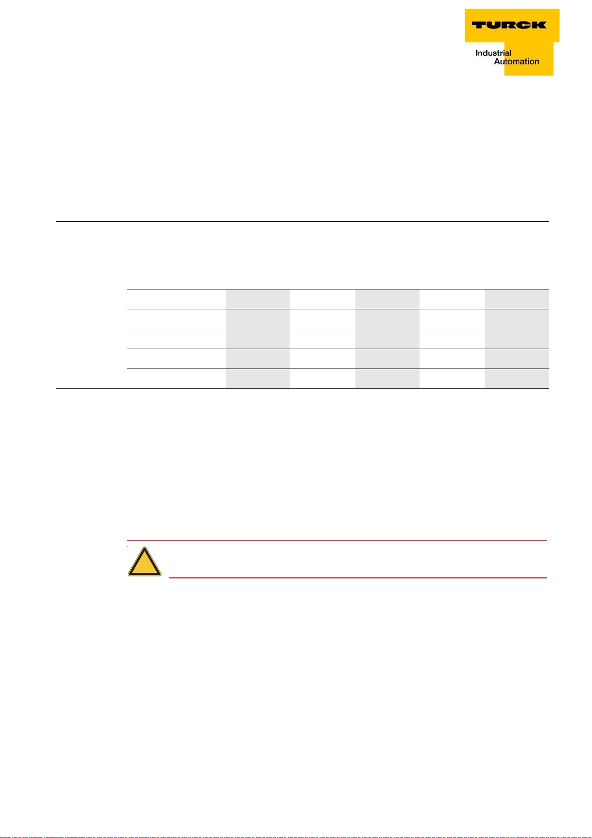
BL×× and CANopen
Transmission Type
The Transmission type determines under which circumstances a PDO can be transmitted or received.
The following PDO Transmission types are supported by BL××:
Type 0 (sync, acyclic)
Type 1 (sync, cyclic)
Type 253 (Remote Request)
Type 255 (Event-Driven)
Table 4:
Overview of
PDO
Transmission
Types
Transmission Type PDO transmission
cyclic acyclic synchr. asynchr. only with RTR
0
1 × ×
253 × ×
255
Type 0
The PDO will always be transmitted (TPDO) or evaluated (RPDO) if this is permitted by a Sync-Frame
transmitted by the SYNC producer and the mapped contents of the BL××-CANopen gateway have
changed since the last transmission.
Type 1
Immediately after receiving each Sync-Frame, the BL××-CANopen gateway puts out the mapped
contents as a PDO on the network, even if they have not changed since the last transmission.
Type 253
The PDO is only transmitted if a transmitted Remote-Frame requests this from the BL××-CANopen
gateway.
× ×
×
Attention
This Transmission Type is only allowed for TPDOs.
Type 255
In this mode of operation, the BL××-CANopen gateway does not depend on any Sync or RemoteRequest for PDO communication. Whenever this is envisaged for an internal event within the
BL××CANopen gateway, the gateway will transmit a PDO to the CANopen network.
The Transmission types of the individual PDOs are independent, which means that a freely mixed
operation with synchronous and asynchronous PDOs is possible.
D301230 - BLxx- CANopen 0511
2-15
Page 30

CANopen
2.3.4 Inhibit Time
The setting of an Inhibit time for the PDOs (Object 1800
TPDOs. Unlike the other time values, which are given as multiples of 1 ms, the Inhibit time is defined as
a multiple of 100 μs. However, since the time resolution of the system clock in the BL××-CANopen
gateway is 1 ms, Inhibit time values below 10 x 100 μs are pointless.
2.3.5 Event Timer
The Event timer (Object 1800
will be transmitted, even though no event has occurred. This means that the Event timer determines
the maximum interval between two transmissions of a TPDO.
The expiry of the interval set for the Event timer is detected as an event. If any other event occurs, the
Event timer is reset and restarted.
The value of the object is interpreted as a multiple of 1 ms.
Available PDOs
BL××:
64 PDOs are supported:
32 Transmit-PDOs: TPDO1 to TPDO32 (Index 1800
32 Receive-PDOs: RPDO1 to RPDO32 (Index 1400
BLCCO:
8 PDOs are supported:
4 Transmit-PDOs: TPDO1 to TPDO4 (Index 1800
4 Receive-PDOs: RPDO1 to RPDO4 (Index 1400
The corresponding Default Master-Slave Connection Set is supported for each of the PDOs 1 to 4, so
that a COB-ID distribution is not necessary for these PDOs.
If one of the COB-IDs from xPDO1 to xPDO4 is reconfigured, then the use of a COB-ID from the Default
Master-Slave Connection Set can be achieved by setting this COB-ID to 0.
ff, Sub-Index 05
hex
ff, Sub-Index 03
hex
) defines the maximum interval after which a TPDO
hex
hex
hex
to 1803
hex
to 1403
hex
to 181F
to 141F
hex
hex
)
hex
hex
)
)
)
) is only supported for
hex
2.3.6 Mapping Objects in PDOs
Mapping is the assignment of objects from an Object Dictionary in a PDO for transmission/reception
through the CAN-bus. More than one object can be transmitted in a single PDO.
The Mapping parameters determine which items of information are transmitted in a PDO:
Table 5:
Object
Dictionary for
mapping
parameters
PDO Object Dictionary entries
Type Product family Range Range
Transmit-PDOs BL20/BL67 TPDO1 to TPDO32 1A00
BLCCO TPDO1 to TPDO4 1A00
Receive-PDOs BL20/BL67 RPDO1 to RPDO32 1600
BLCCO RPDO1 to RPDO4 1600
to 1A1F
hex
to 1A03
hex
to 161F
hex
to 1603
hex
hex
hex
hex
hex
D301230 - BLxx- CANopen 05112-16
Page 31

BL×× and CANopen
Default-PDOs and PDO-mappings
The 4 Transmit and 4 Receive-PDOs which are specified by the Communication Profile CiA DS-301 are
supported by BL××. The mapping of these PDOs and their Transmission types are specified by the I/ODevice Profile CiA DS-401.
In addition to the default PDOs which are standardized by the CiA DS-301 and DS-401 profiles, other
PDOs for a -CANopen gateway may be provided with mapping entries and communication parameters.
These additional PDOs (5 to 16) will be set to "Invalid" as a default (see Table 6: Overview Default-TPDOs
as per CiA DS-301 und DS-401 to Table 9: Overview of the BL××-specific Default-RPDOs).
Default-PDOs as per CiA DS-301 und DS-401
The TPDOs in the following table have the following characteristics:
The COB-ID is part of sub-index 01
The PDO is active!
The first digit of the 8-digit hexadecimal COB-ID-number shows amongst others, if the PDO is valid.
Active PDOs are marked by a hex-digit 7. Normally, the digit is 0 or 4. → Description of the COB-ID
entry (sub-index 01hex ) (page 4-29).
Note
BL67/BL20:
The Default-PDOs are only activated if the planned objects and sub-indices actually exist
for the corresponding PDO. If, in a station, for example no analog
I/Os are used, then the PDOs 2 to 4 are set to "Invalid" and no mapping entries will be present.
hex
D301230 - BLxx- CANopen 0511
2-17
Page 32

CANopen
Overview of the Default-TPDOs as per CiA DS-301 and DS-401
Table 6:
Overview
Default-TPDOs
as per CiA DS301 und DS-401
Table 7:
Overview
Default-RPDOs
as per CiA DS301 und DS-401
Meaning TPDO Sub-Index 01
"COB-ID"
1 group, digital input channels, (bits 0 to 63) PDO1
1800
1 group, analog input channels, (channels 0 to 3) PDO2
1801
2 group, analog input channels, (channels 4 to 7) PDO3
1802
3 group, analog input channels, (channels 8 to 11) PDO4
1803
hex
hex
hex
hex
0000 0180
0000 0280
0000 0380
0000 0480
hex
hex
hex
hex
Overview of the Default-RPDOs as per CiA DS-301 and DS-401
Meaning RPDO COB-ID
-
hex
+ Node-ID
+ Node-ID
+ Node-ID
+ Node-ID
1 group, digital output channels, (bits 0 to 63) PDO1
1400
1 group, analog output channels, (channels 0 to 3) PDO2
1401
2 group, analog output channels, (channels 4 to 7) PDO3
1402
3 group, analog output channels, (channels 8 to 11) PDO4
1403
0000 0200
hex
0000 0300
hex
0000 0400
hex
0000 0500
hex
+ Node-ID
hex
+ Node-ID
hex
+ Node-ID
hex
+ Node-ID
hex
BL××-spezifische Default-PDOs (gilt nicht für BL compact)
These additional PDOs will be set to "Invalid" as a default.
Before enabling these PDOs, the corresponding parameters must be checked. This applies especially to
the COB-IDs, since these are taken from the Default Master-Slave Connection Set, and are assigned to
other Node-IDs. For this reason, other nodes with the corresponding Node-ID must not be present in
the network, or such nodes must not use the corresponding COB-IDs.
The Transmission type of these PDOs is generally 255.
Overview of the BL××-specific Default-TPDOs (not valid for BL compact)
Note
The COB-ID definition for the TPDOs depends on the gateway used in the application (see
EDS file for the gateways).
D301230 - BLxx- CANopen 05112-18
Page 33

BL×× and CANopen
Table 8:
Overview of the
BL××-specific
Default-TPDOs
BL20- -GW-CO BL67-GW-CO/
BL20-GWBR-CANopen
Meaning TPDOs COB-ID TPDO COB-ID TPDO
2 group digital
input channels
PDO5
1804
8000 01C0
hex
+ Node-ID 8000 01C0
hex
hex
(bits 64 to 127)
3 group digital
input channels
PDO6
1805
8000 02C0
hex
+ Node-ID 8000 02C0
hex
hex
(bits 128 to 191)
4 group digital
input channels
PDO7
1806
8000 03C0
hex
+ Node-ID C000 03C0
hex
hex
(bits 192 to 255)
5 group digital
input channels
PDO8
1807
8000 04C0
hex
+ Node-ID C000 04C0
hex
hex
(bits 256 to 319)
1 group encoders
(channels 0 +1)
2 group encoders
(channels 2 3)
PDO9
1808
hex
PDO10
1809
hex
8000 01E0
8000 02E0
+ Node-ID C000 01E0
hex
+ Node-ID C000 02E0
hex
hex
hex
+ Node-ID
+ Node-ID
+ Node-ID
+ Node-ID
+ Node-ID
+ Node-ID
3 group encoders
(channels 4 5)
4 group encoders
(channels 6 7)
4 group analog
input channels
(channels 12 to 15)
5 group analog
input channels
(channels 16 to 19)
6 group analog
input channels
(channels 20 to 23)
7 group analog
input channels
(channels 24 to 27)
1. group RS××
(channel 0)
1. group RS××
(channel 1)
PDO11
180A
PDO12
180B
hex
PDO13
180C
hex
PDO14
180D
PDO15
180E
hex
PDO16
180F
hex
PDO18
1811
hex
PDO19
1812
hex
hex
hex
8000 03E0
8000 04E0
8000 01A0
8000 02A0
+ Node-ID C000 03E0
hex
+ Node-ID C000 04E0
hex
+ Node-ID C000 01A0
hex
+ Node-ID C000 02A0
hex
88000 000 03A0
+ Node-ID
8000 04A0
8000 0000
8000 0000
+ Node-ID C000 04A0
hex
hex
hex
hex
+ Node-ID
hex
+ Node-ID
hex
+ Node-ID
hex
+ Node-ID
hex
C8000 000 03A0
hex
+ Node-ID
+ Node-ID
hex
C000 0000
C000 0000
hex
hex
D301230 - BLxx- CANopen 0511
2-19
Page 34

CANopen
Overview of the BL××-specific Default-TPDOs (not valid for BL compact)
Table 9:
Overview of the
BL××-specific
Default-RPDOs
Meaning RPDOs COB-ID RPDO
2 group, digital input I/Os, (bits 64 to 127) PDO5
1404
hex
3 group, digital input I/Os, (bits 128 to 191) PDO6
1405
hex
4 group, digital input I/Os, (bits 192 to 255) PDO7
1406
hex
5 group, digital input I/Os, (bits 256 to 319) PDO8
1407
hex
1 group encoders (channel 0 + 1) PDO9
1408
hex
2 group encoders (channel 2 + 3) PDO10
1409
hex
3 group encoders (channel 4 + 5) PDO11
140A
hex
8000 0240
8000 0340
8000 0440
8000 0540
8000 0260
8000 0360
8000 0460
+ Node-ID
hex
+ Node-ID
hex
+ Node-ID
hex
+ Node-ID
hex
+ Node-ID
hex
+ Node-ID
hex
+ Node-ID
hex
4 group encoders (channel 6 + 7) PDO12
140B
hex
4 group analog I/Os, (channels 12 to 15) PDO13
140C
hex
5 group analog I/Os, (channels 16 to 19) PDO14
140D
6 group analog I/Os, (channels 20 to 23) PDO15
140E
hex
7 group analog I/Os, (channels 24 to 27) PDO16
140F
hex
1. group RS×× (channel 0) PDO18
1411
hex
1. group RS×× (channel 1) PDO19
1412
hex
Attention
The COB-ID for the RS×××-Module must be defined by the user!
hex
8000 0560
8000 0220
8000 0320
8000 0420
8000 0520
8000 0000
8000 0000
+ Node-ID
hex
+ Node-ID
hex
+ Node-ID
hex
+ Node-ID
hex
+ Node-ID
hex
hex
hex
D301230 - BLxx- CANopen 05112-20
Page 35

BL×× and CANopen
Example (not valid for BLCCO)
The own Node-ID of an BL××-CANopen gateway is 1 . There are more than 12 analog input channels. As
a result, appropriate mapping entries are set up for TPDO13 (Object 1A0C
180C, Sub-Index 1) is pre-loaded with the value 8000 01A1
alteration if a node with the Node-ID 33 (own Node-ID + 32) does not exist, or at least its TPDO1 is not
used.+
The following table illustrates the systematic relationship:
), and the COB-ID (Object
. This PDO can only be enabled without
hex
hex
Table 10:
Relationship
between a
Node-ID and
BL20-specific
PDOs
PDO Node-ID
assigned to this COB-ID in the Default
Master-Slave Connection Set
PDO5 own Node-ID + 64 (40
PDO6 own Node-ID + 64 (40
PDO7 own Node-ID + 64 (40
PDO8 own Node-ID + 64 (40
PDO9 own Node-ID + 96 (60
PDO10 own Node-ID + 96 (60
PDO11 own Node-ID + 96 (60
PDO12 own Node-ID + 96 (60
PDO13 own Node-ID + 32 (20
PDO14 own Node-ID + 32 (20
PDO15 own Node-ID + 32 (20
Original PDO
assigned to this COB-ID in the
Default Master-Slave Connection
Set
)PDO1
hex
)PDO2
hex
)PDO3
hex
)PDO4
hex
)PDO1
hex
)PDO2
hex
)PDO3
hex
)PDO4
hex
)PDO1
hex
)PDO2
hex
)PDO3
hex
PDO16 own Node-ID + 32 (20
)PDO4
hex
D301230 - BLxx- CANopen 0511
2-21
Page 36

CANopen
Mappable Objects
The maximum of 64 mapping entries per PDO that is specified by Communication Profile CiA DS-301 is
supported.
The following objects from the Object Dictionary can be mapped:
Table 11:
Overview of
mappable
objects
A"n" depends on
the used object
as well as on the
used product
Name
Index Sub-index Direction
Dummy Mapping Boolean 0001
Dummy Mapping Boolean Integer8
Dummy Mapping Boolean Integer16
Dummy Mapping Boolean Integer32
Dummy Mapping Boolean Unsigned8
Dummy Mapping Boolean Unsigned16
Dummy Mapping Boolean Unsigned32
Error register
Manu Spec Analog Input Range
RS232/RS4xx RxD
RS232/RS4xx TxD
RFID Input Data U64
0002
0003
0004
0005
0006
0007
1001
5420
5601
5602
5700 1 to n
hex
hex
hex
hex
hex
hex
hex
hex
hex
hex
hex
- Receive
- Receive
- Receive
- Receive
- Receive
- Receive
- Receive
– Transmit
1 to n A Transmit
1 to n Receive
1 to n Transmit
RFID Output Data U64 5702 1 to n
RFID Status 5708 1 to n
Encoder Status 5802
Encoder Flags
SSI Native Status
SSI Optional Encoder Status
Encoder Control
PwmStatus
5803
5805
5806
5808
5902
PwmFlags 5903
PwmControl 5908
PwmPeriodDuration 5920
Read Input 8 Bit 6000
Read Input Bit (1 to 128)
Read Input Bit (129 to 256)
Read Input Bit (257 to 288)
A 6020
6021
6022
hex
hex
hex
hex
hex
hex
hex
hex
hex
hex
hex
hex
hex
1 to n Transmit
1 to n Transmit
1 to n Transmit
1 to n Transmit
1 to n Receive
1 to n
1 to n
1 to n
1 to n
1 to n Transmit
1 to n Transmit
1 to n Transmit
1 to n Transmit
D301230 - BLxx- CANopen 05112-22
Page 37

BL×× and CANopen
Table 11:
Overview of
mappable
objects
Name
Read Input 16 Bit
Read Input 32 Bit
Write Output 8 Bit
Write Output Bit (1 to 128)
Write Output Bit (129 to 256) A
Write Output Bit (257 to 288)
A 6220
6221
6222
Write Output 16 Bit
Write Output 32 Bit
Read Analog Input 16 Bit
Write Analog Output 16 Bit
Preset Value for Multi-Sensor Devices
Position Value for Multi-Sensor Devices
Index Sub-index Direction
6100
6120
6200
6300
6320
6401
6411
6810
6820
hex
hex
hex
hex
hex
hex
hex
hex
hex
hex
hex
hex
1 to n Transmit
1 to n Transmit
1 to n Receive
1 to n Receive
1 to n Receive
1 to n Receive
1 to n Receive
1 to n Receive
1 to n Transmit
1 to n Receive
1 to n Transmit
1 to n Transmit
Table 12:
Abort code
CAM1 State Register
Area State Register
6B00
6C00
hex
hex
1 to n Transmit
1 to n Transmit
Procedure for Altering PDO-Mappings
The Communication Profile CiA DS-301 Version 4 defines a detailed procedure for altering PDOmappings.
For the gateway, this results in the following method for modifying PDO-mappings:
The node state of the gateway must be "Pre-Operational".
The number of mapping entries (Sub-index 0) for a PDO must be set to 0.
The mapping entries (Sub-index 1 to 64) can be written.
The number of mapping entries (Sub-index 0) must now be set to the valid number of mapped
objects.
Alternatively, the new mapping can be saved in non-volatile memory (Store Communication
parameters).
The following abort codes (Abort-Domain-Protocol) may be sent back by the gateway in case of an
error:
Abort code Description as per
Possible cause
CiA DS-301
0604 0041
hex
Object cannot be mapped Invalid object-index transferred while writing
the mapping entries.
0604 0042
hex
D301230 - BLxx- CANopen 0511
Number or length of the
objects exceeds the PDO
length
Attempted to map too many or excessively
long objects to a PDO. This will be returned on
writing to the sub-index 0.
2-23
Page 38

CANopen
Table 12:
Abort code
Abort code Description as per
CiA DS-301
0609 0011
0800 0022
hex
hex
Sub-index does not exist. A sub-index > 64 was addressed.
Access not possible in this
node state
Possible cause
Write access is only possible in the "Preoperational" node state. Write access to Subindices 1 to 64 is only possible if sub-index 0 is
written with value 0.
2.3.7 Commands for "Parameter Save" and "Restore Defaults"
Parameter changes that are made through SDO access are only stored in volatile memory. All
alterations that are made by the user will be replaced by default values at the next Reset
Communication, Reset Node or Power-ON-Boot-Up.
With BL××0, it is possible to use a command to make a permanent save of the communication and/or
application parameters. This is done through the "Store parameters" command (Object 1010
index 1 to 3).
The command is executed by using an SDO to write the data contents 6576 6173
the following entries:
1010
1010
1010
sub-index 1 saves all parameters
hex
sub-index 2 saves all parameters
hex
sub-index 3 saves all device parameters (see CiA DS-301 V4.01)
hex
sub-
hex
("save") to one of
hex
Table 13:
Data contents
0x6576 6173
(„save“)
Table 14:
Data contents
0x6461 6F6C
(„load“)
MSB LSB
ASCII evas
hex
65
hex
76
hex
61
hex
73
hex
Since in some circumstances it may not be possible to restore the original memory contents after a lot
of alterations, BL×× supports the "Restore default Parameter" command (Object 1011
3) with the following data contents: 6461 6F6C
("load").
hex
sub-index 1 to
hex
MSB LSB
ASCII daol
hex
64
hex
61
hex
6F
hex
6C
hex
The division of the Sub-entries corresponds to that for the "Store parameters" command.
After the command "Restore default parameters", a Reset Node must be carried out, followed by a
"Store parameters" command. The default values are only saved again when this last command is
executed.
D301230 - BLxx- CANopen 05112-24
Page 39

3 Object dictionary - overview of all objects
3.1 Overview of all objects ...................................................................................................................... 2
D301230 - BLxx- CANopen 0511 3-1
Page 40

Object dictionary - overview of all objects
3.1 Overview of all objects
The following table provides an overview of all objects supported by the BL××-CANopen gateway.
Table 15:
Overview of all
objects
Index Name
Objects (according to CiA CS-301)
1000
1001
1005
1008
1009
100A
100C
100D
1010
1011
1014
1016
1017
Device Type XXXXsee Kapitel 4
hex
hex
hex
hex
hex
hex
hex
hex
hex
hex
hex
hex
hex
Error register XXXX
SYNC COB-ID XXXX
Device Name XXXX
Manufacturer Hardware Version XXXX
Manufacturer Software Version XXXX
Guard Time XXXX
Lifetime Factor XXXX
Store Parameters XXXX
Restore Default Parameters XXXX
Emcy COB-ID XXXX
Consumer Heartbeat Time XXXX
Producer Heartbeat Time XXXX
BL××-GWBR-CANOPEN
B67-GW-CANOPEN
BL××-E-GW-CO
BLCCO-xxx
1018
1020
1027
1200
1203
1400
1403
1404
141F
1600
1603
1604
161F
hex
hex
hex
hex
hex
hex
hex
hex
hex
hex
hex
hex
hex
to
to
to
to
to
Identity Object XXXX
Verify Configuration XXXX
Module List XXX
Server SDO Parameters XXXX
Receive PDO Communication
XXXX
Parameters (1 to 4)
Receive PDO Communication
XXX
Parameters (5 to 32)
Receive PDO-Mapping Parameters
XXXX
(1 to 4)
Receive PDO-Mapping Parameters
XXX
(5 to 32)
D301230 - BLxx- CANopen 05113-2
Page 41

Overview of all objects
Table 15:
Overview of all
objects
Index Name
1800
1803
1800
181F
1A00
1A03
1A04
1A1F
1F80
1F81
1F82
1F83
to
hex
hex
to
hex
hex
to
hex
hex
to
hex
hex
hex
hex
,Request NMT XXX
hex
hex
Transmit PDO-Parameters (1 to 4) XXXXsee Kapitel 4
Transmit PDO-Parameters (5 to 32) XXX
Transmit PDO-Mapping Parameters
(1 to 4)
Transmit PDO-Mapping Parameters
(5 to 32)
NMT Startup XXX
Slave Assignment XXX
Request Guarding XXX
Manufacturer specific objects
2000
2010
2400
hex
hex
hex
Serial Number XXXX
Node Reset Modifiers XXXX
System Voltages X
BL××-GWBR-CANOPEN
B67-GW-CANOPEN
BL××-E-GW-CO
BLCCO-xxx
XXXX
XXX
2401
3000
3002
3004
300B
3020
3022
3024
302B
3040
3042
3044
304B
3060
hex
hex
hex
hex
hex
hex
hex
hex
hex
hex
hex
hex
hex
hex
to
to
to
System Voltages X
XBIInputByte XXXXsee Kapitel 14
XBIInputWord XXXX
XBIInputDWord0 to XBIInputDWord8 XXXX
XBIOutputByte XXXX
XBIOutputByte XXXX
XBIOutputDWord0 to
XXXX
XBIOutputDWord8
XBIDiagByte XXXX
XBIDiagWord XXXX
XBIDiagDWord0 to XBIDiagDWord8 XXXX
XBIParamByte XXXX
D301230 - BLxx- CANopen 0511
3-3
Page 42

Object dictionary - overview of all objects
Table 15:
Overview of all
objects
Index Name
3062
3064
306B
3081
3084
3085
3086
3087
3090
3091
3094
3095
3096
3097
hex
hex
hex
hex
hex
hex
hex
hex
hex
hex
hex
hex
hex
hex
to
XBIParamWord XXXXsee Kapitel 14
XBIParamDWord0 to XBIParamDWord8 XXXX
XBIReferenceModuleType XXXX
XBIReferenceInputSize XXXX
XBIReferenceOutputSize XXXX
XBIReferenceDiagSize XXXX
XBIReferenceParamSize XXXX
XBICurrentModuleId XXXX
XBICurrentModuleType XXXX
XBICurrentInputSize XXXX
XBICurrentOutputSize XXXX
XBICurrentDiagSize XXXX
XBICurrentParamSize XXXX
BL××-GWBR-CANOPEN
B67-GW-CANOPEN
BL××-E-GW-CO
BLCCO-xxx
5420
5440
5600
5601
5602
5801
5802
5803
5804
5805
5806
5808
5810
hex
hex
hex
hex
hex
hex
hex
hex
hex
hex
hex
hex
hex
Analog Input Mode XXXXsee Kapitel 8
Analog Output Mode XXXXsee Kapitel 9
RS232/RS4xx parameters XXXXsee Kapitel 10
RS232/RS4xx RxD XXXX
RS232/RS4xx TxD XXXX
Encoder Config XXXXsee Kapitel 11
Encoder Status XXXX
Encoder Flags XXXX
Encoder Diag XXXX
Encoder Native Status XXXX
Encoder Optional Encoder XXXX
Encoder Control XXXX
Encoder Load Prepare Value X X
D301230 - BLxx- CANopen 05113-4
Page 43

Overview of all objects
Table 15:
Overview of all
objects
Index Name
5811
5820
5821
5822
5823
5824
5825
5827
5830
5831
5840
5901
5902
5903
hex
hex
hex
hex
hex
hex
hex
hex
hex
hex
hex
hex
hex
hex
Encoder Pulse Width X Xsee Kapitel 11
Measuring Integration Time X X
Measuring Low Limit
Measuring High Limit
Measuring Units Per Revolution
Encoder Measuring Divisor X X
Encoder Measuring Factor X X
Encoder Measuring Time Out X X
Encoder Measuring Value X X
Encoder Latch Value X X
SSI Diag Mapping XXX
PWM Config X X
PWM Status X X
PWM Flags X X
BL××-GWBR-CANOPEN
B67-GW-CANOPEN
BL××-E-GW-CO
BLCCO-xxx
5904
5908
5910
5913
5920
5931
hex
hex
hex
hex
hex
hex
PWM Diag X X
PWM Control X X
PWM Load Prepare Value X X
PWM Duty Cycle X X
PWM Period Duration X X
PWM Latch Value X X
I/O module objects (according to CiA CS-401)
6000
6020
6021
6022
6100
6120
hex
hex
hex
hex
hex
hex
Read Input 8 Bit XXXXsee Kapitel 5
Read Input Bit 1 to 128 XXXX
Read Input Bit 129 to 256 XXXX
Read Input Bit 257 to 288 XXXX
Read Input 16 Bit XXXX
Read Input 32 Bit XXXX
and Kapitel 7
D301230 - BLxx- CANopen 0511
3-5
Page 44

Object dictionary - overview of all objects
Table 15:
Overview of all
objects
Index Name
6200
6206
6207
6220
6222
6250
6252
6260
6262
6300
6306
6307
6320
6326
6327
hex
hex
hex
hex
hex
hex
hex
hex
hex
hex
hex
hex
hex
hex
hex
to
to
to
Write Output 8 Bit XXXXsee Kapitel 6
Error Mode Output 8 Bit XXXX
Error Value Output 8 Bit XXXX
Write Output Bit 1 to 128 to Write
Output Bit 257 to 288
Error Mode Output Bit 1 to 128 to Error
Mode Output Bit 257 to 288
Error Value Output Bit 1 to 128 to Error
Value Output Bit 257 to 288
Write Output 16 Bit XXXX
Error Mode Output 16 Bit XXXX
Error Value Output 16 Bit XXXX
Write Output 32 Bit XXXX
Error Mode Output 32 Bit XXXX
Error Value Output 32 Bit XXXX
BL××-GWBR-CANOPEN
B67-GW-CANOPEN
BL××-E-GW-CO
BLCCO-xxx
and Kapitel 7
XXXX
XXXX
XXXXsee Kapitel 6
6401
6411
6421
6422
6423
6424
6425
6426
6427
6428
Read Analog Input 16 Bit XXXXsee Kapitel 8
hex
hex
hex
Write Analog Output 16 Bit XXXXsee Kapitel 9
Analog Input Interrupt Trigger
XXXXsee Kapitel 8
Auswahl
hex
hex
hex
Analog Input Interrupt Source XXXX
Analog Input global Interrupt Enable XXXX
Analog Input Interrupt Upper Limit
XXXX
Integer
hex
Analog Input Interrupt lower Limit
XXXX
Integer
hex
hex
Analog Input Interrupt Delta Unsigned XXXX
Analog Input Interrupt Negative Delta
XXXX
Unsigned
hex
Analog Input Interrupt Positive Delta
XXXX
Unsigned
D301230 - BLxx- CANopen 05113-6
Page 45

Overview of all objects
Table 15:
Overview of all
objects
Index Name
6443
6444
67FF
hex
hex
hex
Analog Output Error Mode XXXXsee Kapitel 9
Analog Output Error Value Integer XXXX
Device Type XXXXsee Kapitel 4
I/O module objects (according to CiA DS-406)
6800
6810
6820
6B00
6B00
6B00
6B10
6B20
67FF
6FFF
hex
hex
hex
hex
hex
hex
hex
hex
hex
hex
Operating parameters XXXXsee Kapitel 11
Preset Value for Multi-Sensor Devices XXXX
Position Value for Multi-Sensor Devices XXXX
CAM State Register XXXX
CAM Enable Register XXXX
CAM Polarity Register XXXX
CAM1 Low Limit XXXX
CAM1 High Limit XXXX
Device TypeDS401 XXXX
Device TypeDS406 XXXX
BL××-GWBR-CANOPEN
B67-GW-CANOPEN
BL××-E-GW-CO
BLCCO-xxx
D301230 - BLxx- CANopen 0511
3-7
Page 46

Object dictionary - overview of all objects
D301230 - BLxx- CANopen 05113-8
Page 47

4 Device (gateway) objects
4.1 Objects of the Communication Profile (acc. to CiA DS-301) ............................................................. 2
4.1.1 Object 1000
4.1.2 Object 1001
4.1.3 Object 1005
4.1.4 Object 1008
4.1.5 Object 1009
4.1.6 Object 100A
4.1.7 Object 100C
4.1.8 Object 100D
4.1.9 Object 1010
4.1.10 Object 1011
4.1.11 Object 1014
4.1.12 Object 1016
4.1.13 Object 1017
4.1.14 Object 1018
4.1.15 Object 1020
4.1.16 Object 1027
4.2 Objects for the Transfer of Service Data ......................................................................................... 20
4.2.1 Objects 1200
4.3 Objects for the Transfer of Process Output Data ............................................................................ 21
– Device Type...............................................................................................................5
hex
– Error Register ............................................................................................................5
hex
– SYNC COB-ID................................... .... ... ....................................... ... ... ... ... ..............6
hex
– Device Name.............................................................................................................7
hex
– Manufacturer Hardware Version ................. ... .... ... ... ... ....................................... ... ... .8
hex
– Manufacturer Software Version ................................................................................8
hex
– Guard Time...............................................................................................................9
hex
– Lifetime Factor ............................................................... .... ...................................... .9
hex
– Store Parameters........................... ... .... ...................................... .... ... ... ... ...............10
hex
– Restore Default Parameters ....................................................................................11
hex
– Emcy COB-ID................. ... ... .... ...................................... .... ... ... ... ............................12
hex
– Consumer Heartbeat Time.......... ... ... ....................................... ... .... ... ... ..................13
hex
– Producer Heartbeat Time........................................................................................15
hex
– Identity Object.........................................................................................................16
hex
– Verify Configuration.................................................................................................17
hex
– Module List.................................. ... ....................................... ... ... .... ... .....................19
hex
to 1203
hex
– Server SDO Default Parameters ..........................................................20
hex
4.3.1 Object 1400
4.3.2 Object 1600
to 141F
hex
to 161F
hex
– Receive PDO Comm. Default Parameters .............................................21
hex
– Receive PDO-Mapping Parameter.........................................................24
hex
4.4 Objects for the Transfer of Process Input Data ...............................................................................27
4.4.1 Object 1800
to 181F
hex
– Transmit PDO-Parameters.....................................................................27
hex
– Inhibit time.......................................................................................................................................30
– Event Timer......................................................................................................................................30
4.4.2 Objects 1A00
to 1A1F
hex
- Transmit PDO Mapping Parameter......................................................30
hex
4.5 Objects for network management (not valid for BLCCO)................................................................ 33
4.5.1 Object 1F80
4.5.2 Object 1F81
4.5.3 Object 1F82
4.5.4 Object 1F83
– NMT Start-up.............................. ... ... .... ...................................... .... ... ... ... ...............33
hex
– Slave Assignment....................................................................................................34
hex
– Request NMT..........................................................................................................36
hex
– Request Guarding ...................................................................................................38
hex
4.6 Overview about the objects of the Device Profile (acc. to CiA DS-401 and 406) ............................. 39
4.6.1 Object 67FF
4.6.2 Object 6FFF
– Device Type.............................................................................................................39
hex
– Device Type.............................................................................................................40
hex
4.7 Manufacturer specific device objects.............................................................................................. 40
4.7.1 Object 2000
4.7.2 Object 2010
4.7.3 Object 2400
4.7.4 Object 2401
– Serial Number..........................................................................................................40
hex
– Node ResetModifiers...............................................................................................41
hex
- System Voltages (only BL67)...................................................................................45
hex
- System Currents (only BL67)...................................................................................45
hex
D301230 - BLxx- CANopen 0511 4-1
Page 48

Device (gateway) objects
4.1 Objects of the Communication Profile (acc. to CiA DS-301)
The following table provides an overview of the supported entries in the object directory which are
defined through the Communication Profile CiA DS-301.
The column Object shows the object type.
The column Name shows the predefined symbolic name of the entry.
The column Typ shows the entry's data type predefined in CiA DS-301.
The column Access shows the access options for the entry. These are:
rw (read/write)
ro (read only)
const (constant) = a read-only constant
The column M/O/C indicates if the entry is Mandatory, Optional or Conditional (depending on the
Device Type, e. g. modular or compact device).
Table 16:
Object overview for the
communication
Profile CiA
DS-301
Index (hex) Object Name Type Access M/O/C
1000
1001
1005
1008
1009
hex
hex
hex
hex
hex
VAR Device Type (page 4-5) Unsigned32 const M
ARRAY Error Register (page 4-5) Unsigned8 ro M
VAR SYNC COB-ID (page 4-6) Unsigned32 rw O
VAR Device Name (page 4-7) Vis-String const O
VAR Manufacturer Hardware Version
Vis-String const O
(page 4-8)
100A
hex
VAR Manufacturer Software Version
Vis-String const O
(page 4-8)
100C
100D
1010
1011
hex
hex
hex
hex
VAR Guard Time (page 4-9) Unsigned32 rw O
VAR Lifetime Factor (page 4-9) Unsigned32 rw O
ARRAY Store Parameters (page 4-10) Unsigned32 rw O
ARRAY Restore Default Parameters
Unsigned32 rw O
(page 4-11)
1014
1016
1017
1018
1020
1027
hex
hex
hex
hex
hex
hex
VAR Emcy COB-ID (page 4-12) Unsigned32 rw O
ARRAY Consumer Heartbeat Time
Unsigned32 rw O
(page 4-13)
VAR Producer Heartbeat Time
Unsigned16 rw O
(page 4-15)
RECORD Identity Object (page 4-16)Identity ro O
ARRAY Verify Configuration (page 4-17) Unsigned32 rw O
ARRAY Module List (page 4-19) Unsigned16 ro C
D301230 - BLxx- CANopen 05114-2
Page 49

Objects of the Communication Profile (acc. to CiA DS-301)
Table 16:
Object overview for the
communication
Profile CiA
DS-301
Index (hex) Object Name Type Access M/O/C
Server SDO Parameter
1200
1201
hex
hex
RECORD 1st Server SDO Parameter
(page 4-20)
RECORD 2nd Server SDO Parameter
SDO-
ro O
Parameters
SDO-parameters rw O
(page 4-20)
1202
hex
RECORD 3rd Server SDO Parameter
SDO-parameters rw O
(page 4-20)
1203
hex
RECORD 4th Server SDO Parameter
SDO-parameters rw O
(page 4-20)
Receive PDO Communication Parameters
1400
hex
RECORD 1st Receive PDO Parameter
PDO CommPar rw O
(page 4-21)
1401
hex
RECORD 2nd Receive PDO Parameter
PDO CommPar rw O
(page 4-21)
1402
hex
RECORD 3rd Receive PDO Parameter
PDO CommPar rw O
(page 4-21)
... ... ... ... ... ...
141F
hex
RECORD 32nd Receive PDO Parameter
PDO CommPar rw O
(page 4-21)
Receive PDO-Mapping Parameters
1600
hex
ARRAY 1st Receive PDO-Mapping
PDO mapping rw O
(page 4-24)
1601
hex
ARRAY 2nd Receive PDO-Mapping
PDO mapping rw O
(page 4-24)
1602
hex
ARRAY 3rd Receive PDO-Mapping
PDO mapping rw O
(page 4-24)
... ... ... ... ... ...
161F
hex
ARRAY 32nd Receive PDO-Mapping
PDO mapping rw O
(page 4-24)
Transmit PDO Communication Parameter
1800
hex
RECORD 1st Transmit PDO Parameter
PDO CommPar rw O
(page 4-27)
1801
hex
D301230 - BLxx- CANopen 0511
RECORD 2nd Transmit PDO Parameter
(page 4-27)
PDO CommPar rw O
4-3
Page 50

Device (gateway) objects
Table 16:
Object overview for the
communication
Profile CiA
DS-301
Index (hex) Object Name Type Access M/O/C
1802
hex
RECORD 3rd Transmit PDO Parameter
PDO CommPar rw O
(page 4-27)
... ... ... ... ... ...
181F
hex
RECORD 32nd Transmit PDO Parameter
(page 4-27)
PDO
CommPar
rw O
Transmit PDO-Mapping Parameter
1A00
hex
ARRAY 1st Transmit PDO-Mapping
PDO mapping rw O
(page 4-30)
1A00
hex
ARRAY 2nd Transmit PDO-Mapping (
PDO mapping rw O
page 4-30)
1A02
hex
ARRAY 3rd Transmit PDO-Mapping
PDO mapping rw O
(page 4-30)
... ... ... ... ... ...
1A1F
hex
ARRAY 32nd Transmit PDO Mapping
NMT Master Objects
1F80
1F81
1F82
1F83
hex
hex
hex
hex
VAR NMT Start-up (page 4-33) Unsigned32 rw O
ARRAY Slave Assignment (page 4-34) Unsigned32 rw O
ARRAY Request NMT (page 4-36) Unsigned8 rw O
ARRAY Request Guarding (page 4-38) Unsigned8 rw O
PDO mapping rw O
(page 4-30)
D301230 - BLxx- CANopen 05114-4
Page 51

Objects of the Communication Profile (acc. to CiA DS-301)
4.1.1 Object 1000
Object 1000
The value FFFF 0191
Table 17:
Object 1000
Object description
hex
INDEX 1000
Name Device Type
Object code VAR
Data type Unsigned32
Value range
Access ro
PDO mapping No
Value range Unsigned32
Default value, BL×× FFFF 0191
Default value, BL×× depends on the respective module
– Device Type
hex
contains the Type and Function for the station.
hex
indicates that all Device Profiles are supported.
hex
hex
hex
4.1.2 Object 1001
The object 1001
the internal errors that occur.
Table 18:
Object 1001
Error register
Object description
hex
INDEX 1001
Name Error register
Object code VAR
Data type Unsigned8
Value range
Access ro
PDO mapping Optional
Value range Unsigned8
Default value, BL×× 00
– Error Register
hex
contains the Error register for the CANopen gateway. It thus contains, in one byte,
hex
hex
hex
Bit 0 Bit 1 Bit 2 Bit 3 Bit 4 Bit 5 Bit 6 Bit 7
Generic Current Voltage 0 Comm. 0 0Manu.
D301230 - BLxx- CANopen 0511
4-5
Page 52

Device (gateway) objects
Abbreviations:
Abbr. Meaning Valid for Modules
generic General error all modules
Current Output short-circuit/ current error DO, AI,TC
Voltage voltage error PF, DO, AI, AO
Comm. communication error all modules
Manu. Manufacturer-specific error all modules
4.1.3 Object 1005
Object 1005
(→ „Identifier for the die standard objects“) of the synchronization object (SYNC). The BL××-CANopengateway is not able to generate, but only to receive, SYNC messages.
Structure of the SYNC COB-ID entry (Unsigned32):
MSB LSB
Bits
11-bit ID
29-bit ID
Table 19:
Description of
the SYNC COBID entry
31 30 29 28 to 11 10 to 0
×00 00 0000 0000 0000 0000 11-bit Identifier
×01 29-bit Identifier
Bit no. Value Description
31 (MSB)
30
29
– SYNC COB-ID
hex
defines the COB-ID and thus the priority
hex
Xfixed
0
1
0
1
Module does not generate a SYNC message
Module generates a SYNC message
11-bit ID (CAN 2.0A) for BL××
29-bit ID (CAN 2.0B)
28 to 11
10 to 0 (LSB)
Note
Bit 30 is static, i.e. cannot be changed.
0
X
if bit 29 = 0
if bit 29 = 1 bits 28 to 11 of the SYNC-COB-ID
X bits 10 to 0 of the SYNC-COB-ID
D301230 - BLxx- CANopen 05114-6
Page 53

Objects of the Communication Profile (acc. to CiA DS-301)
Table 20:
Object 1005
Object description
hex
INDEX 1005
Name COB-ID
Object code VAR
Data type Unsigned32
Value range
Access rw
PDO mapping No
Value range Unsigned32
Default value, BL×× 0000 0080h
4.1.4 Object 1008
Object 1008
Table 21:
Object 1008
Object description
hex
hex
– Device Name
hex
contains the manufacturer-specific device name
hex
INDEX 1008
hex
Name manufacturer specific device name
Object code VAR
Data type Visible String
Value range
Access const.
PDO mapping No
Value range, BL×× –
Default value depends on the gateway/ module
D301230 - BLxx- CANopen 0511
4-7
Page 54

Device (gateway) objects
4.1.5 Object 1009
Object 1009
Table 22:
Object 1009
Object description
hex
INDEX 1009
Name Hardware version
Object code VAR
Data type Visible String
Value range
Access const.
PDO mapping No
Value range, BL×× –
Default value, BL×× depends on the gateway/ module
4.1.6 Object 100A
Object 100A
– Manufacturer Hardware Version
hex
contains the designation for the Hardware Version.
hex
hex
– Manufacturer Software Version
hex
contains the device's software version.
hex
Table 23:
Object 100A
Object description
hex
INDEX 100A
Name Software version
Object code VAR
Data type Visible String
Value range
Access const.
PDO mapping No
Value range, BL×× –
hex
D301230 - BLxx- CANopen 05114-8
Page 55

Objects of the Communication Profile (acc. to CiA DS-301)
4.1.7 Object 100C
Object 100C
100D
hex
Table 24:
Object 100C
Object description
hex
INDEX 100C
Name Guard Time
Object code VAR
Data type Unsigned16
Value range
Access rw
PDO mapping No
Value range, BL×× Unsigned16
Default value, BL×× 0
– Guard Time
hex
contains the Guard time in milliseconds. The product of "Lifetime factor" (Object
hex
) and Guard time is the "Lifetime" for the Node Guarding.
hex
4.1.8 Object 100D
If the Lifetime factor is multiplied by the Guard time, the result is the Lifetime for Node Guarding.
Example:
Guard Time .........100 ms
Lifetime Factor:..............3
With a Guard Time of 100 ms, the network nodes expect a guard telegram every 100 ms. The Lifetime
factor enables a setting to be made in the BL××-gateway for how often a Guard Frame from the Master
can be missed before an error condition is recognized. In this example, the relevant time would be 300
ms. The evaluation would only become active after the message had been missing for 300 ms.
Table 25:
Object 100D
Object description
hex
INDEX 100D
Name Lifetime Factor
Object code VAR
Data type Unsigned8
Value range
Access rw
– Lifetime Factor
hex
hex
PDO mapping No
Value range, BL×× Unsigned8
Default value, BL×× 0
D301230 - BLxx- CANopen 0511
4-9
Page 56

Device (gateway) objects
4.1.9 Object 1010
The object 1010
executed by writing the data contents 6576 6173
Table 26:
Object 1010
Object description
hex
INDEX 1010
Name Store Parameters
Object code 3
Data type Unsigned32
Value description
Sub-index 00
Description Largest Supported Index
Access ro
PDO mapping No
Default value, BL×× 3
Sub-index 01
– Store Parameters
hex
can be used to save parameter changes in non-volatile memory. The command is
hex
hex
hex
hex
hex
hex
("save") to one of the Sub-indices.
hex
Description Save all Parameters
Access rw
PDO mapping No
Value range, BL×× Unsigned32
Default value, BL×× -
Sub-index 02
hex
Description Save Communication Parameters
Access rw
PDO mapping No
Value range, BL×× Unsigned32
Default value, BL×× -
Sub-index 03
hex
Description Save Application Parameters
Access rw
PDO mapping No
Value range, BL×× Unsigned32
Default value, BL×× -
D301230 - BLxx- CANopen 05114-10
Page 57

Objects of the Communication Profile (acc. to CiA DS-301)
4.1.10 Object 1011
The object 1011
the data contents 6461 6F6C
Table 27:
Object 1011
Object description
hex
INDEX 1011
Name Restore Default Parameters
Object code ARRAY
Data type 3
Value description
Sub-index 00
Description Largest Supported Index
Access ro
PDO mapping No
Sub-index 01
– Restore Default Parameters
hex
can be used to restore the default parameters. The command is executed by writing
hex
("load") to one of the Sub-indices.
hex
hex
hex
hex
hex
Description Restore All Default Parameters
Access rw
PDO mapping No
Value range, BL×× Unsigned32
Default value, BL×× -
D301230 - BLxx- CANopen 0511
4-11
Page 58

Device (gateway) objects
Table 27:
Object 1011
Object description
hex
Value description
Sub-index 02
Description Restore Communication Parameters
Access rw
PDO mapping No
Value range, BL×× Unsigned32
Default value, BL×× -
Sub-index 03
Description Restore Application Parameters
Access rw
PDO mapping No
Value range, BL×× Unsigned32
hex
hex
Default value, BL×× -
4.1.11 Object 1014
Object 1014
MSB LSB
Bits
11-bit ID
29-bit ID
Table 28:
Description of
the Emcy COBID entry
31 30 29 28 to 11 10 to 0
0/1 0 0 00 0000 0000 0000 0000 11-bit Identifier
0/1 0 1 29-bit Identifier
Bit no. Value Description
31 (MSB) 0
30 0 reserved (always 0)
29 0
– Emcy COB-ID
hex
contains the Identifier for the Emergency Messages
hex
EMCY exists/ is valid
1
EMCY does not exist/ is not valid
11-bit ID (CAN 2.0A) ∅ for BL××
1
29-bit ID (CAN 2.0B)
28 to 11 0
if bit 29 = 0
X
if bit 29 = 1 bits 28 to 11 of 29-bit-COB-ID
D301230 - BLxx- CANopen 05114-12
Page 59

Objects of the Communication Profile (acc. to CiA DS-301)
Table 28:
Description of
the Emcy COBID entry
Table 29:
Object 1014
hex
Bit no. Value Description
10 to 0
X bits 10 to 0 of COB-ID
(LSB)
Note
Bit 30 is static, i.e. cannot be changed.
Object description
INDEX 1014
hex
Name Emcy COB-ID
Object code VAR
Data type Unsigned32
Value description
Access rw
PDO mapping No
Value range, BL×× Unsigned32
Default value, BL×× 0000 0080
4.1.12 Object 1016
The Heartbeat Protocol is used to monitor the operational capability of other CANopen bus nodes. The
Heartbeat Protocol must be seen as an alternative to Node-/Life-Guarding, which, unlike Guarding,
does not use Remote-Frames.
A device generates the Heartbeat with a specific cycle time (see object 1017
time"). Another device receives the Heartbeat and monitors the cycle time. Another device receives the
Heartbeat and monitors the cycle time.
Object 1016 defines the cycle time (interval) at which the Heartbeat is expected. This cycle time should
be longer than the corresponding cycle time for the transmitter (see object 1017
the Heartbeat starts when the first Heartbeat Frame is received. If the Consumer heartbeat time = 0,
then the corresponding entry will not be used.
The time is set as a multiple of 1 ms.
Structure of the entry for Consumer heartbeat time (Unsigned32):
MSB LSB
– Consumer Heartbeat Time
hex
+ Node-ID
hex
"Producer heartbeat
hex
). The monitoring of
hex
Bits
Value
Data type
31 to 24 23 to 16 15 to 0
reserved (default: 00
–Unsigned8Unsigned16
D301230 - BLxx- CANopen 0511
hex
Node-ID Heartbeat Time
4-13
Page 60

Device (gateway) objects
Table 30:
Object 1016
Object description
hex
INDEX 1016
hex
Name Consumer Heartbeat Time
Object code ARRAY
Data type Unsigned32
Value description
Sub-index 00
hex
Description Number of Entries
Category Mandatory
Access ro
PDO mapping No
Value range, BL×× 1
Default value, BL×× 1
Sub-index 01
hex
Description Consumer Heartbeat Time
Category Mandatory
Access rw
PDO mapping No
Value range, BL×× Unsigned32
Default value, BL×× 0
D301230 - BLxx- CANopen 05114-14
Page 61

Objects of the Communication Profile (acc. to CiA DS-301)
4.1.13 Object 1017
The object 1017
If the cycle time = 0, then Heartbeat will not be used. The content of the object is interpreted as a
multiple of 1 ms.
Table 31:
Object 1017
Object description
hex
INDEX 1017
Name Producer Heartbeat Time
Object code VAR
Data type Unsigned16
Value description
Access rw
PDO mapping No
Value range, BL×× Unsigned16
Default value, BL×× 0
– Producer Heartbeat Time
hex
defines the cycle time for the Heartbeat.
hex
hex
D301230 - BLxx- CANopen 0511
4-15
Page 62

Device (gateway) objects
4.1.14 Object 1018
Object 1018
he Vendor-ID (Sub-index
manufacturer-specific Product-Code (Sub-index 02
manufacturer-specific Revision-Number (Sub-index 03
minor revision number. The major revision number defines a special CANopen functionality. If the
CANopen functionality is expanded, then the major revision number must be incremented. The minor
revision number identifies various versions that have the same CANopen functionality.
Bits
Value
Table 32:
Object 1018
Object description
hex
INDEX 1018
Name Device Specification
Object code RECORD
Data type Identity
Value description
– Identity Object
hex
contains general information about the BL×× gateway.
hex
) is a unique ID which precisely identifies the manufacturer. The
hex
) identifies a specific device version. The
hex
hex
MSB LSB
31 to 16 15 to 0
Major Revision Number Minor Revision Number
hex
) consists of a major revision number and a
Sub-index 00
hex
Description Number of Entries
Category Mandatory
Access ro
PDO mapping No
Default value, BL×× 4
Value description
Sub-index 01
hex
Description Manufacturer-ID
Category Mandatory
Access ro
PDO mapping No
Value range, BL×× Unsigned32
Default value, BL×× 0000 009C
hex
D301230 - BLxx- CANopen 05114-16
Page 63

Objects of the Communication Profile (acc. to CiA DS-301)
Table 32:
Object 1018
Object description
hex
Sub-index 02
Description Product Code
Category Option
Access ro
PDO mapping No
Value range, BL×× Unsigned32
Sub-index 03
Description Revision number
Category Option
Access ro
PDO mapping No
Value range, BL×× Unsigned32
hex
hex
Default value, BL×× No
Sub-index 04
Description Serial number
Category Option
Access ro
PDO mapping No
Value range, BL×× Unsigned32
4.1.15 Object 1020
Object 1020
The BL××-CANopen gateway supports the non-volatile storage of parameters. A network configuration
tool or an CANopen Manager can use object 1020
so check whether a reconfiguration is necessary. The configuration tool saves the time and date
simultaneously in object 1020
configuration and the signature will be restored, either automatically on request. If the configuration
values are altered by some other command, then the object will be set to 0.
The Configuration Manager compares the signature and the configuration with the values from the
DCF file. If it discovers any deviations, a reconfiguration will be necessary.
hex
– Verify Configuration
hex
is used to check the station configuration after a device reset.
hex
to test the station configuration after a reset, and
hex
and the corresponding DCF file. After a reset, the most recent
hex
D301230 - BLxx- CANopen 0511
4-17
Page 64

Device (gateway) objects
Table 33:
Object 1020
Object description
hex
INDEX 1020
hex
Name Verify Configuration
Object code ARRAY
Data type Unsigned16
Value description
Sub-index 00
hex
Description Number of entries
Access rw
PDO mapping No
Default value, BL×× 02
Sub-index 01
hex
hex
Description Configuration date
Access rw
PDO mapping No
Value range, BL×× Unsigned32
Default value, BL×× No
Sub-index 02
hex
Description Configuration time
Access rw
PDO mapping No
Value range, BL×× Unsigned32
Default value, BL×× No
Note
The configuration date contains the number of days since January 01 1984. The configuration
time contains the number of milliseconds since midnight.
D301230 - BLxx- CANopen 05114-18
Page 65

Objects of the Communication Profile (acc. to CiA DS-301)
4.1.16 Object 1027
Object 1027
It is only valid for modular devices and thus not for BLCCO.
Table 34:
Object 1027
Object description
hex
INDEX 1027
Name Module List
Object code ARRAY
Data type Unsigned16
Access ro
Value description
Sub-index 00
Description Number of connected
Access ro
PDO mapping No
– Module List
hex
describes all the actually installed modules in a station.
hex
hex
hex
modules
Value range, BL×× 00
hex
to 4A
hex
Default value, BL×× No
Sub-index 01
hex
Description Module 1
... ...
BL20 BL67
Sub-index 4A
hex
20
hex
Description Module 74 Module 32
The sequential Sub-indices 01
hex
to 4A
(BL20) or resp. 20
hex
(BL67) describe the corresponding BL××
hex
modules in the sequence in which they are installed in the station. Each entry contains a number that
identifies the particular module. Each entry contains a number which identifies the respective module.
Note
There is one identifier for each type of BL×× module.
In the EDS-file, the individual extensions to object 1027
(e.g. M1SubExt1027) for all the optional BL××
hex
module types are listed in the section [Supported Modules]. The default values (e.g. default
value=8000
) correspond to the identifiers for the particular module types (e.g.[M1ModuleInfo]
hex
ProductName=Generic BL××-BR/-PF).
D301230 - BLxx- CANopen 0511
4-19
Page 66

Device (gateway) objects
4.2 Objects for the Transfer of Service Data
4.2.1 Objects 1200
Objects 1200
The priority of the data is defined through the Identifier/ COB-ID
Table 35:
Object 1200
to 1203
hex
Object description
hex
INDEX 1200
Name Server SDO Parameters
Object code RECORD
Number of Elements 3
Data type SDO-parameters
Value description
Sub-index 00
Description Number of entries
Access ro
PDO mapping No
to 1203
hex
hex
hex
to 1203
– Server SDO Default Parameters
define the priority for the transmission of SDO1 to SDO4.
hex
to 1203
hex
hex
hex
hex
Default value, BL×× 02
Sub-index 01
hex
hex
Description COB-ID Client Server (rx)
Access Index 1200
Index 1201
:ro
hex
to 1203
hex
PDO mapping No
Value range, BL×× Unsigned32
Default value, BL×× Index 1200
0000 0600
Index 1201
Sub-index 02
hex
:
hex
+ Node-ID
hex
to 1203
hex
Description COB-ID Server Client (rx)
Access Index 1200
Index 1201
:ro
hex
to 1203
hex
PDO mapping No
Value range, BL×× Unsigned32
hex
hex
hex
:rw
:rwNo
:rw
D301230 - BLxx- CANopen 05114-20
Page 67

Objects for the Transfer of Process Output Data
Table 35:
Object 1200
to 1203
hex
Object description
hex
Default value, BL×× Index 1200
0000 0580
Index 1201
:
hex
+ Node-ID
hex
to 1203
hex
4.3 Objects for the Transfer of Process Output Data
The objects 1400
to be transferred via RPDO. In addition to that, the priority and the transmission type for the RPDOtransfer are defined.
Object 1400
hex
object-index, the sub-index and the data length for the data which have to be transferred via RPDO1.
Objects 1401
The priority of the data is defined through the Identifier/ COB-ID
The values are already entered by default for objects 1400
A station with up to 64 digital outputs and 12 analog outputs therefore transfers the process output
data automatically via RPDOs.
to 141F
hex
define, together with objects 1600
hex
defines the priority and the transmission type for the RPDO1. Object 1600
and 1601
hex
thus define the RPDO2, etc.
hex
hex
:rwNo
hex
to 161F
hex
to 1403
and 1600
hex
, which output data have
hex
defines the
hex
to 1603
hex
hex
.
4.3.1 Object 1400
Objects 1400
The priority is defined via the identifier/COB-ID (see „Identifier for the Standard Objects”) in sub-index
.
01
hex
With the highest bit of sub-index 01
respective highest
The transmission type is defined with the sub-index 02
Which data content is to be transferred with the RPDO1 to RPDO32 is defined with the objects 1600
to 161F
Table 36:
Object 1400
to 141F
hex
Object description BL×× BLC
hex
INDEX 1400
Name Receive PDO Parameters
Object code RECORD
Data type PDO CommPar
Value description
to 141F
hex
.
hex
to 141F
hex
– Receive PDO Comm. Default Parameters
hex
define the priority for the transmission of RPDO11 to RPDO32.
hex
, the further content can be defined as valid/invalid. The
adecimal number is then > 8.
hex
hex
to 141F
hex
hex
.
hex
1400
to 1403
hex
hex
hex
Sub-index 00
Description Maximum Number of Entries
Access ro
D301230 - BLxx- CANopen 0511
hex
4-21
Page 68

Device (gateway) objects
Table 36:
Object 1400
to 141F
hex
Object description BL×× BLC
hex
PDO mapping No
Value range, BL×× 2
Default value, BL×× 02
Sub-index 01
hex
hex
Description COB-ID for the PDOs (see Table 37:)
Access rw
PDO mapping No
Value range, BL×× Unsigned32
Default value, BL×× Index 1400
Index 1401
Index 1402
Index 1403
Index 1404
to 141F
hex
: 0000 0200
hex
: 0000 0300
hex
: 0000 0400
hex
: 0000 0500
hex
:
hex
reserved
+ Node-ID
hex
+ Node-ID
hex
+ Node-ID
hex
+ Node-ID
hex
-
Sub-index 02
hex
Description Transmission type (see Table 38:)
Access rw
PDO mapping No
Value range, BL×× Unsigned8
Default value, BL×× FF
hex
D301230 - BLxx- CANopen 05114-22
Page 69

Objects for the Transfer of Process Output Data
Structure of the COB-ID entry
MSB LSB
Bits 31 30 29 28 to 11 10 to 0
11-bit ID 0/1 0/1 0 00 0000 0000 0000 0000 11-bit Identifier
29-bit ID 0/1 0/1 1 29-bit Identifier
Table 37:
Description of
the COB-IDentry
Table 38:
Description of
the
Transmission
Type
Bit no. Value Meaning
31 (msb) 0 PDO exists / is valid
1 PDO does not exist / is invalid
30 0 RTR is possible in this PDO
1 RTR is not possible in this PDO
29 0 11-Bit-ID (CAN 2.0A) (standard application)
1 29-bit ID (CAN 2.0B)
28 to 11 0 if bit 29=0 (Standard application)
X if bit 29 = 1 bits 28 to 11 of COB-ID
10 to 0 (lsb) X bits 10 to 0 of COB-ID
The Transmission type (Sub-index 02
Transmission
PDO transmission
) can have the following values:
hex
Type
2 to 254 reserved
255 ×
D301230 - BLxx- CANopen 0511
cyclic acyclic synchr. asynchr. only with RTR
0××
1× ×
4-23
Page 70

Device (gateway) objects
4.3.2 Object 1600
Objects 1600
RPDO1 to RPDO32 (BLCCO: RPDO1 to RPDO 4).
The data content (here: process output data) is represented by product specific mappable objects.
→ Mappable Objects (page 2-22)
For example, the process output data for the digital channels are entered in objects 6200
etc.
The description of these objects can be found in the following chapter.
Sub-indices 01
number, the sub-index and the length of the data that have to be transferred via the respective RPDO.
An RPDO can transfer a maximum number of 8 bytes (64 bit).
The number of sub-indices depends on the data length. For larger projects, it has to be calculated and
entered by user.
At a data length of 8 bit, 8 sub-indices are needed to represent a total number of 64 bit. At a data length
of 1 bit, 64 sub-indices are needed to represent a total number of 64 bit.
Objects 1600
output channels and for the first 12 analog output channels, provided that the values are represented
by the objects 6200
Table 39:
Object 1600
to 161F
hex
Object description BL×× BLCCO
hex
to 161F
hex
– Receive PDO-Mapping Parameter
hex
to 161F
hex
ff. of the objects 1600
hex
to 1603
hex
(BLCCO: 1600
hex
(RPDO1 to RPDO4) references by default the values for the first 64 digital
hex
(digital values) and 6411
hex
hex
to 161F
hex
to 1603
hex
hex
(analog values).
hex
) define, which data have to be transferred with
, 6220
(BLCCO: 1600
to 1603
hex
hex
) contain the object
hex
hex
INDEX 1600
to 161F
hex
hex
1600
to 1603
hex
hex
Name Receive PDO-Mapping Parameters
Object code RECORD
Data type PDO mapping
Value description
Sub-index 00
Description NumberOfMappedApplication
hex
Objects
Receive PDO-Mapping
Parameters
Access rw rw
PDO mapping No No
Value range, BL×× 0 to 64 -
Default value, BL×× see Table 16: -
Sub-index 01
hex
Description 1st Mapping Object
Access rw
PDO mapping No
D301230 - BLxx- CANopen 05114-24
Page 71

Objects for the Transfer of Process Output Data
Table 39:
Object 1600
to 161F
hex
Object description BL×× BLCCO
hex
Value range, BL×× Unsigned32
Default value, BL×× see Table 16:
... ...
Sub-index 40
hex
Description 64th Mapping Object 4th Mapping Object
Access rw rw
PDO mapping No No
Value range, BL×× Unsigned32 Unsigned32
Default value, BL×× No No
Default values for objects 1600
to 1603
hex
hex
:
Note
The number of mapping objects, which are automatically generated by the gateway during
start-up, depends on the actual physical structure of the BL××-station.
03
hex
Table 40:
Default values
for objects
hex
hex
to
1600
1603
Object Product Sub-
index
1600
hex
BL×× 01
hex
... ... ...
08
hex
1601
hex
BLCCO 01
BL×× 01
hex
hex
... ... ...
04
hex
BLCCO 01
hex
Default value Description valid for
6200 0108
1st Mapping Object
hex
RPDO1
(digital output)
6200 0808
8th Mapping Object
hex
(digital output)
6200 0108
1st Mapping Object
hex
RPDO1
(digital output)
6411 0110
1st Mapping Object
hex
RPDO2
(analog output)
6411 0410
4th Mapping Object
hex
(analog output)
6411 0110
1st Mapping Object
hex
RPDO2
(analog output)
D301230 - BLxx- CANopen 0511
4-25
Page 72

Device (gateway) objects
Table 40:
Default values
for objects
hex
hex
to
1600
1603
Object Product Sub-
index
1602
hex
BL×× 01
hex
... ... ...
04
hex
BLCCO
1603
hex
BL×× 01
hex
... ... ...
04
hex
BLCCO 01
hex
Default value Description valid for
6411 0510
1st Mapping Object
hex
RPDO3
(analog output)
6411 0810
4th Mapping Object
hex
(analog output)
6411 0910
1st Mapping Object
hex
RPDO4
(analog output)
6411 0C10
4th Mapping Object
hex
(analog output)
6411 0510
1st Mapping Object
hex
RPDO4
(analog output)
D301230 - BLxx- CANopen 05114-26
Page 73

Objects for the Transfer of Process Input Data
The following structure applies to the parameters for sub-indices:
Structure of the PDO Mapping entries:
MSB LSB
Index (16 bit) Sub-Index (8 bit) Object length (8 bit)
Note
To change the number of mapping entries, follow the instructions in section .
Procedure for Altering PDO-Mappings (page 2-23).
4.4 Objects for the Transfer of Process Input Data
Objects 1800
(BLCCO: 1A00
the mode for the data transfer via TPDO.
Object 1800
type for TPDO1. Object 1A00
which have to be transferred via TPDO1.
Objects 1801
The priority of the data is defined through the Identifier/ COB-ID
The values are already entered by default for objects 1800
A station with up to 64 digital outputs and 12 analog outputs therefore transfers the process input data
automatically via TPDOs.
4.4.1 Object 1800
Objects 1800
inhibit time and the event timer for TPDO1 to TPDO32.
The priority is defined via the identifier/COB-ID (see „Identifier for the Standard Objects”) in sub-index
.
01
hex
With the highest bit of sub-index 01
respective highest
The transmission type is defined with the sub-index 02
The inhibit time is defined in sub-index 03
The maximum time between 2 transmissions, the event timer, is defined in sub-index 05
Which data content is to be transferred with the RPDO1 to RPDO32 is defined with the objects 1A00
to 1A1F
to 181F
hex
to 1A03
hex
defines the priority, the minimum inhibit time, the event timer and the transmission
hex
and 1A01
hex
to 181F
hex
to 181F
hex
. (BLCCO: 1A00
hex
(BLCCO: 1800
hex
), which input data are transferred. Additionally they define the priority and
hex
defines the object-index, the sub-index and the data length for the data
hex
thus define the TPDO2, etc.
hex
– Transmit PDO-Parameters
hex
(BLCCO: 1800
hex
adecimal number is then > 8.
hex
to 1A03
hex
to 1803
hex
to 1803
hex
, the further content can be defined as valid/invalid. The
hex
.
hex
).
hex
) define, together with objects 1A00
hex
to 1803
hex
) define the priority, the transmission type, the
hex
.
hex
and 1A00
hex
hex
hex
to 1A03
hex
to 1A1F
.
hex
.
hex
hex
Table 41:
Object 1800
to 181F
hex
Object description BL×× BLCCO
hex
INDEX 1800
Name Transmit PDO-parameters
Object code RECORD
D301230 - BLxx- CANopen 0511
to 181F
hex
hex
1800
to 1803
hex
hex
4-27
Page 74

Device (gateway) objects
Table 41:
Object 1800
to 181F
hex
Object description BL×× BLCCO
hex
Data type PDO CommPar
Value description
Sub-index 00
Description Highest Sub-Index Used
Access ro
PDO mapping No
Value range 5
Default value No
Sub-index 01
Description COB-ID of the PDO
Access rw
PDO mapping No
hex
hex
Value range, BL×× Unsigned32
Default value, BL×× Index 1800
Index 1801
Index 1802
Index 1803
Index 1804
to 181F
hex
: 0000 0180
hex
: 0000 0280
hex
: 0000 0380
hex
: 0000 0480
hex
:-
hex
Value description
Sub-index 02
hex
Description Transmission Type
Access rw
PDO mapping No
Value range, BL×× Unsigned8
Default value, BL×× FFh
Sub-index 03
hex
Description Inhibit Time
+ Node-ID
hex
+ Node-ID
hex
+ Node-ID
hex
+ Node-ID
hex
Access rw
PDO mapping No
Value range, BL×× Unsigned16
D301230 - BLxx- CANopen 05114-28
Page 75

Objects for the Transfer of Process Input Data
Table 41:
Object 1800
to 181F
hex
Object description BL×× BLCCO
hex
Default value, BL×× 0
Sub-index 04
Description reserved
Sub-index 05
Description Event Timer
Access rw
PDO mapping No
Value range, BL×× Unsigned16 (0 is not used)
Default value, BL×× 0
The COB-ID (sub-Index 01
) shows the following structure:
hex
hex
hex
MSB LSB
Bits 31 30 29 28 to 11 10 to 0
11-bit ID 0/1 0/1 0 00 0000 0000 0000 0000 11-bit Identifier
29-bit ID 0/1 0/1 1 29-bit Identifier
Table 42:
Bit no. Value Description
Description of
the COB-ID
entry (sub-index
)
01
hex
31 (MSB) 0 PDO exists / is valid
1 PDO does not exist / is invalid
30 0 RTR is possible in this PDO
1 RTR is not possible in this PDO
29 0 11-Bit-ID (CAN 2.0A) (standard application)
1 29-bit ID (CAN 2.0B)
28 to 11 0 if bit 29=0 (Standard application)
10 to 0 (LSB) X bits 10 to 0 of COB-ID
D301230 - BLxx- CANopen 0511
X if bit 29 = 1 bits 28 to 11 of COB-ID
4-29
Page 76

Device (gateway) objects
Table 43:
Transmission
Type
The Transmission type (Sub-index 02
Transmission
PDO transmission
) can have the following values:
hex
Type
cyclic acyclic synchr. asynchr. only with RTR
0××
1× ×
2 to 252 reserved
253 × ×
254 reserved
255 ×
Inhibit time
In order to avoid a permanent occupation of the field bus by high-prior messages, the Inhibit Time is
defined.
With sub-Index 03
, the Inhibit time is defined as a multiple of 100 μs. However, since the time
hex
resolution of the system clock in the BL××-CANopen gateway is 1 ms, Inhibit time values below 10 x 100
μs are pointless.
Event Timer
Sub-index 03
defines the maximum interval after which a TPDO will be transmitted, even though no
hex
event has occurred. The expiry of the interval set for the Event timer is detected as an event.
If any other event occurs, the Event timer is reset and restarted.
The value of the object is interpreted as a multiple of 1 ms.
4.4.2 Objects 1A00
Die Objects 1A00
with TPDO1 to TPDO32.
The data content (here: process input data) is represented by product specific mappable objects.
see Mappable Objects (page 2-22)
For example, the process input data for the digital channels are entered in objects 6000
The description of these objects can be found in the following chapter.
Sub-indices 01
number, the sub-index and the length of the data that have to be transferred via the respective TPDO.
A TPDO can transfer a maximum number of 8 bytes (64 bit).
The number of sub-indices depends on the data length. For larger projects, it has to be calculated and
entered by user.
At a data length of 8 bit, 8 sub-indices are needed to represent a total number of 64 bit. At a data length
of 1 bit, 64 sub-indices are needed to represent a total number of 64 bit.
to 1A1F
hex
- Transmit PDO Mapping Parameter
hex
to 1A1F
hex
ff. of the objects 1A00
hex
(BLCCO: 1A00
hex
to 1A1F
hex
to 1A03
hex
) define, which data have to be transferred
hex
(BLCCO: 1A00
hex
to 1A03
hex
, 6020
hex
) contain the object
hex
hex
etc.
D301230 - BLxx- CANopen 05114-30
Page 77

Objects for the Transfer of Process Input Data
Table 44:
Object 1A00
to 1A1F
hex
Objects 1600
to 1603
hex
(RPDO1 to RPDO4) references by default the values for the first 64 digital
hex
output channels and for the first 12 analog output channels, provided that the values are represented
by the objects 6000
(digital values) and 6401
hex
(analog values).
hex
Object description BL×× BLCCO
hex
INDEX 1A00
to 1A1Fh 1A00
hex
to 1A03h
hex
Name Transmit PDO-Mapping Parameters
Object code RECORD
Data type PDO mapping
Value description
Sub-index 00
Description Number of Mapped Application
hex
Objects in the PDO
Transmit PDO-Mapping
Parameters
Access rw
PDO mapping No
Value range, BL×× 0 deactivated
1 to 64: activated
Default value, BL×× see Table 38:
Sub-index 01
hex
Description 1st Mapping Object
Access rw
PDO mapping No
Value range, BL×× Unsigned32
Default value, BL×× see page 4-32
...
Sub-index 40
hex
Description 64th Mapping Object
Access rw
PDO mapping No
Value range, BL×× Unsigned32
Default value, BL×× No
D301230 - BLxx- CANopen 0511
4-31
Page 78

Device (gateway) objects
Table 45:
Default values
for objects
hex
hex
to
1A00
1A03
Default values for objects 1A00
Note
The number of mapping objects, which are automatically generated by the gateway during
start-up, depends on the actual physical structure of the BL××-station.
Object Product Sub-
Index
1A00
hex
BL×× 01
hex
...
08
hex
1A00
hex
BLCCO 01
BL×× 01
hex
hex
to 1A03
hex
hex
:
Default value Description valid for
6000 0108
1st Mapping Object
hex
(digital input)
... ...
6000 0808
8th Mapping Object
hex
(digital input)
6000 0108
1st Mapping Object
hex
(digital input)
6401 0110
1st Mapping Object
hex
(analog input)
TPDO1
TPDO1
TPDO2
1A02
1A03
hex
hex
...
04
BLCCO 01
BL×× 01
...
04
BLCCO 01
BL×× 01
...
04
BLCCO 01
hex
hex
hex
hex
hex
hex
hex
hex
... ...
6401 0410
6401 0110
6401 0510
hex
hex
hex
... ...
6401 0810
6401 0510
6401 0910
hex
hex
hex
... ...
6401 0C10
6401 0910
hex
hex
4th Mapping Object
(analog input)
1st Mapping Object
(analog input)
1st Mapping Object
(analog input)
4th Mapping Object
(analog input)
1st Mapping Object
(analog input)
1st Mapping Object
(analog input)
4th Mapping Object
(analog input)
1st Mapping Object
(analog input)
TPDO3
TPDO3
TPDO4
TPDO4
D301230 - BLxx- CANopen 05114-32
Page 79

Objects for network management (not valid for BLCCO)
The following structure applies to the parameters for sub-indices 01
MSB LSB
Index (16 bit) Sub-Index (8 bit) Object length (8 bit)
Note
To change the number of mapping entries, follow the instructions in section Procedure for
Altering PDO-Mappings (page 2-23).
4.5 Objects for network management (not valid for BLCCO)
Objects 1F80
Master. The activation is done via bit 0 from object 1F80
4.5.1 Object 1F80
Object 1F80
Table 46:
Object 1F80
to 1A1F
hex
Object description
hex
hex
to 1F83
hex
– NMT Start-up
describes the start-up behavior of BL×× in NMT (Network-Management).
hex
are only relevant if the BL××-station is to work as a Network Management
hex
hex
ff.:
hex
.
Table 47:
Structure of the
NMT-Start-up
INDEX 1F80
hex
Name NMT Start-up
Object code VAR
Data type Unsigned32
Access rw
Bit Value Meaning
0 0 BL×× station is not the NMT-Master All further bits will be ignored.
The objects in the network list will be ignored.
1 BL×× is the NMT-Master
1 0 Only the explicitly selected slaves will be started.
1 After boot-up, the service "NMT Start Remote Node All Nodes" will be
performed.
2 0 BL×× moves automatically to the "Operational" state.
1 BL×× does not automatically move to the "Operational" state. The status
change is defined through the respective application.
3 0 Starting of the slave is permitted.
D301230 - BLxx- CANopen 0511
1 Starting of the slave is not permitted.
4-33
Page 80

Device (gateway) objects
Table 47:
Bit Value Meaning
Structure of the
NMT-Start-up
4 0 An error event in an obligatory slave deals with the slave individually.
5 to 31 Reserved; set to 0
4.5.2 Object 1F81
Object 1F82
Management (NMT). It contains information on error control and on actions which will be enganged
through error events. All other parameters for a slave are only valid if this slave is described in object
1F81
hex
Table 48:
Object 1F81
Object description
hex
1 An error event in an obligatory slave triggers an NMT Reset All Nodes (see
– Slave Assignment
hex
describes, as per CiA DSP-302, all the slaves that can be connected to Network
hex
object 1F81
hex
, bit 3).
.
Note
Object 1F81
is only valid if BL×× is defined as NMT Master (see „Object 1F80
hex
hex
“, Bit 0).
INDEX 1F81
hex
Name Slave Assignment
Object code ARRAY
Data type Unsigned32
Access rw
Value description
Sub-index 00
hex
Description Maximum Number of Entries
Access rw
PDO mapping No
Value range 1 to 127
Default value 127
Sub-index 01
hex
Description Slave with Node-ID 1
Access rw
PDO mapping No
Value range, BL×× Unsigned32
...
D301230 - BLxx- CANopen 05114-34
Page 81

Objects for network management (not valid for BLCCO)
Table 48:
Object 1F81
hex
Table 49:
Structure of the
object 1F81
hex
Slave
Assignment
Object description
Sub-index 3Fh
Description Slave with Node-ID 63
Access rw
PDO mapping No
Value range, BL×× Unsigned32
Default value, BL×× No
Note
Each sub-index corresponds to the slave with the respective Node-ID. The sub-index with the
Node-ID of the NMT-Master will be ignored.
Byte Bit Value Meaning
0 0 0 The node with this ID is not a slave.
1 The node with this ID is not a slave. After configuration, the
node will be put into the "Operational" state.
1 0 An error event or other event detection by a slave during boot-
up leads to information from the application.
1 An error event or other event detection by a slave during boot-
up leads to information from the application and to automatic
start of Error Control Services.
2 0 An error event or other event detection by a slave during boot-
up does not lead to information from the application or
automatic start of Error Control Services.
1 An error event or other event detection by a slave during boot-
up leads to the start of "Start Boot Slaves".
3 0 Optional slave: the network can also be started if this node is
not connected.
1 Mandatory slave: the network will not be started if this node is
not connected during the slave boot-up.
4 0 The slave can be reset by the "NMT Reset Communication"
command, depending on its state.
D301230 - BLxx- CANopen 0511
1 The NMT-Master does not have to send an "NMT Reset
Communication" command for this slave, if the slave is in the
"Operational" state.
4-35
Page 82

Device (gateway) objects
Table 49:
Byte Bit Value Meaning
Structure of the
object 1F81
hex
Slave
Assignment
0
1 8 bit value for the Retry Factor
2 to 3 0 16 bit value for the Guard time
4.5.3 Object 1F82
Object 1F82
Management (NMT).
5 0 Verification of the application software version is not required
for this node.
1 Verification of the application software version is required for
this node.
6 0 Automatic update of the application software (download) is not
permitted.
1 Automatic update of the application software (download) is
permitted.
7 Reserved; set to 0
– Request NMT
hex
describes, as per CiA DSP-302, all the slaves that can present queries to the Network
hex
Table 50:
Object 1F82
Object description
hex
INDEX 1F82
Name Query NMT
Object code ARRAY
Data type Unsigned8
Access ro/rw
Value description
Sub-index 00
Description Supported Number of Slaves
Access ro
PDO mapping No
Value 128
Sub-index 01
hex
hex
hex
Description Request NMT-Service for slave with Node-ID 1
Access rw
D301230 - BLxx- CANopen 05114-36
Page 83

Objects for network management (not valid for BLCCO)
Table 50:
Object 1F82
Object description
hex
PDO mapping No
Value range, BL×× Unsigned8
Default value, BL×× No
Sub-index 3Fh
Description Request NMT-Service for slave with Node-ID
Access rw
PDO mapping No
Value range, BL×× Unsigned8
Default value, BL×× No
Sub-index 80
Description Request NMT-Service for all slaves
63
hex
Table 51:
Value range
Access wo
PDO mapping No
Value range, BL×× Unsigned8
Default value, BL×× No
For a write access to this object, the value corresponds to the state for the node to which the query is
directed. For read access, the object contains the present state of the node.
Status Value for
Write access
Value for
Read access
Stopped 4 4
Operational 5 5
Reset Node 6 –
Reset Communication 7 –
Pre-Operational 127 127
unknown – 0
Node missing – 1
D301230 - BLxx- CANopen 0511
4-37
Page 84

Device (gateway) objects
4.5.4 Object 1F83
Object 1F83
Management (NMT).
Table 52:
Object 1F83
Object description
hex
INDEX 1F83
Name Request Guarding
Object code ARRAY
Data type Unsigned8
Access ro/rw
Value description
Sub-index 00
Description Supported Number of Slaves
Access ro
PDO mapping No
Value 128
– Request Guarding
hex
describes, as per CiA DSP-302, all the slaves that can be monitored through the Network
hex
hex
hex
Sub-index 01
hex
Description Request NMT-Service for slave with Node-ID 1
Access rw
PDO mapping No
Value range, BL×× Unsigned8
Value 0 = Slave being monitored at present
1 = Slave not being monitored at present
...
Sub-index 7Fh
Description Request Guarding for Slave with
Node-ID 63
Access rw
PDO mapping No
Value range Unsigned8
Value 0 = Slave being monitored at present
1 = Slave not being monitored at present
D301230 - BLxx- CANopen 05114-38
Page 85

Overview about the objects of the Device Profile (acc. to CiA DS-401 and 406)
Table 52:
Object 1F83
Object description
hex
Sub-index 80
hex
Description Request Start/Stop Guarding for all slaves
Access wo
PDO mapping No
Value range, BL×× Unsigned8
Default value, BL×× No
4.6 Overview about the objects of the Device Profile (acc. to CiA DS-401 and 406)
4.6.1 Object 67FF
The object 67FF
The object contains the value 000x0191
Das Low-Word (0191
the high word (000x
– Device Type
hex
specifies the type of the first device profile supported.
hex
.
hex
) specifies the device profile (acc. to CiA DS-401: I/O modules).
hex
) the I/O-types, see CiA DS-401.
hex
Table 53:
Object 67FF
Feature Description/ Value
hex
Name Device Type
Object code VAR
Data type Unsigned32
Access ro
Default value No
PDO mapping No
D301230 - BLxx- CANopen 0511
4-39
Page 86

Device (gateway) objects
4.6.2 Object 6FFF
Object 6FFF
– Device Type
hex
(corresponds to object 67FF
hex
second device profile supported.
The object contains the value 000A0191
The low word (0196
The high word (000A
= 406dez) specifies the device profile.
hex
) describes the encoder type in accordance with CiA DS-406 (10dec = Multi
hex
Sensor Encoder Interface).
Table 54:
Object 6FFF
Feature Description
hex
Name Device Type
Object code VAR
PDO Mapping No
Data type Unsigned32
Access ro
4.7 Manufacturer specific device objects
in accordance with CiA DS-406) specifies the type of the
hex
.
hex
4.7.1 Object 2000
Object 2000
used BL××-gateway.
– Serial Number
hex
corresponds to sub-index 04
hex
Note
We recommend using object 1018
of object 1018
hex
, sub-index 04
hex
and contains the ident-number of the
hex
for the serial number.
hex
D301230 - BLxx- CANopen 05114-40
Page 87

Manufacturer specific device objects
4.7.2 Object 2010
Object 2010
Table 55:
Object 2010
Object description
hex
INDEX 2010
Name Node ResetModifiers
Object code ARRAY
Data type Unsigned32
Value description
Sub-index 00
Description Number of Entries
Access ro
PDO mapping No
Value range, BL×× Unsigned8
Default value, BL×× No
– Node ResetModifiers
hex
is used for a temporary (volatile) modification to the module behavior.
hex
hex
hex
Sub-index 01
hex
Description Hard Reset Node Identifier
Access rw
PDO mapping No
Value range, BL×× Unsigned32
Default value, BL×× No
Sub-index 02
hex
Description Save Reference Reset Modifier
Access rw
PDO mapping No
Value range, BL×× Unsigned32
Default value, BL×× No
D301230 - BLxx- CANopen 0511
4-41
Page 88

Device (gateway) objects
Table 55:
Object 2010
hex
Table 56:
Hard Reset
(processor reset)
selection
Object description
Sub-index 03
hex
Description Save Current Reset Modifier
Access rw
PDO mapping No
Value range, BL×× Unsigned32
Default value, BL×× No
The Hard-Reset-Modifier determines whether, in the event of a Reset Node command, a normal fast
reset should be performed, or a hard processor reset, which can take several seconds to be carried out.
For writing, the value that is transferred in Unsigned 32 format will be interpreted as a string:
MSB LSB
tsrh
74
hex
73
hex
72
hex
68
hex
Table 57:
Normal Reset
selection
Table 58:
Selection: "Save
and HardwareReset"
MSB LSB
tsrs
74
hex
73
hex
72
hex
73
hex
After the next Reset-Node or the next "Reset Communication" command, the operating mode will in all
cases be reset to "normal Reset Node".
2010
at BL××
hex
The Index "Save reference module list" determines that, in the event of a Reset Node command, the
BL×× reference module list (Objects 3080
and 3081
hex
) will be saved in non-volatile memory, and
hex
then followed by a hard processor reset. This hardware reset is necessary, because changes to the
BL××0 reference module list cannot be dynamically accepted in the CANopen I/O mirror. If the module
list is altered, all the CANopen parameters will be reset to the default values.
For writing, the value that is transferred in Unsigned 32 format will be interpreted as a string:
MSB LSB
vasr
76
hex
61
hex
73
hex
72
hex
D301230 - BLxx- CANopen 05114-42
Page 89

Manufacturer specific device objects
Table 59:
Normal Reset
selection
Table 60:
Save and Hardware-Reset
selection
MSB LSB
tsrs
74
hex
73
hex
72
hex
73
hex
After the next Reset-Node or the next "Reset Communication" command, the operating mode will in all
cases be reset to "normal Reset Node".
The Index "Save Current Reset Modifier" determines that, in the event of a Reset Node command, the
actual BL×× module list (Objects 3090
and 3091
hex
) will be saved in non-volatile memory, and then
hex
followed by a hard processor reset. This hardware reset is necessary, because changes to the reference
module list cannot be dynamically accepted in the CANopen I/O mirror. If the module list is altered, all
the CANopen parameters will be reset to the default values.
For writing, the value that is transferred in Unsigned 32 format will be interpreted as a string:
MSB LSB
vasc
76
hex
61
hex
73
hex
63
hex
Table 61:
Normal Reset
selection
MSB LSB
tsrs
74
hex
73
hex
72
hex
73
hex
After the next Reset-Node or the next "Reset Communication" command, the operating mode will in all
cases be reset to "normal Reset Node".
D301230 - BLxx- CANopen 0511
4-43
Page 90

Device (gateway) objects
D301230 - BLxx- CANopen 05114-44
Page 91

Manufacturer specific device objects
4.7.3 Object 2400
This object enables the reading of up to 4 system voltages.
At the moment, the BL67-GW-CO supports the reading of U
give out 0.
Table 62:
Object 2400
Object description
hex
INDEX 2400
Name System Voltages
Object code ARRAY
Data type Unsigned16
Access ro
PDO mapping No
Default value No
4.7.4 Object 2401
This object enables the reading of up to 4 system currents.
- System Voltages (only BL67)
hex
hex
- System Currents (only BL67)
hex
from sub-index 1. The sub-indices 2...4
sys
Table 63:
Object 2401
Object description
hex
INDEX 2401
Name System Currents
Object code ARRAY
Data type Unsigned16
Access ro
PDO mapping No
Default value No
hex
D301230 - BLxx- CANopen 0511
4-45
Page 92

Device (gateway) objects
D301230 - BLxx- CANopen 05114-46
Page 93

5 Objects for digital input modules
5.1 Digital input modules BL×× .............................................................................................................. 2
5.2 General object overview for digital input modules .......................................................................... 2
5.2.1 Object 6000
5.2.2 Object 6020
Object 6022
5.2.3 Object 6100
5.2.4 Object 6120
– Read Input 8 Bit ........................................................................................................4
hex
– Read Input Bit (1 to 128), Object 6021
hex
– Read Input Bit (257 to 288) .......................................................................................5
hex
– Read Input 16 Bit ......................................................................................................6
hex
– Read Input 32 Bit ......................................................................................................6
hex
– Read Input Bit (129 to 256),
hex
D301230 - BLxx- CANopen 0511 5-1
Page 94

Objects for digital input modules
5.1 Digital input modules BL××
The objects are used in the following modules:
Table 64:
BL×× - digital
input modules
Product family Module
BL20 BL20-×DI-24VDC-P
BL20-×DI-24VDC-N
BL20-2DI-120/230VAC
BL20-4DI-NAMUR
BL20-E-×DI-24VDC-P
BL67 BL67-×DI-P
BL67-×DI-N
BL67-×DI-PD
BLC miscellaneous
5.2 General object overview for digital input modules
Table 65:
General object
overview for
digital input
modules
Object Name Page
3064
6000
6020
hex
hex
hex
XBIParam Dword page 14-10
Read Input 8 Bit page 5-4
Read Input Bit 1 to 128 page 5-5
6021
6022
6100
6120
hex
hex
hex
hex
Read Input Bit 129 to 256 page 5-5
Read Input Bit 257 to 288 page 5-5
Read Input 16 Bit page 5-6
Read Input 32 Bit page 5-6
D301230 - BLxx- CANopen 05115-2
Page 95

General object overview for digital input modules
1800h1A00h
Transmit
PDO1
Map
into
TPDO1
Single
Digital
Input
{Unsigned8}
CAN
Transmission
Entry
into
6000h
Default
Mapping
Parameter
Default
Communication
Parameter
{8 Byte} {TPDO1}
{1, 0}
Fixed
Relation
Hardware Objects
Communication Objects
The following figure shows the relationship between the digital input objects for an 8-bit access:
Figure5:
Relationship
between the
digital
digital input
modules
(according to CiA
Standard DS401)
D301230 - BLxx- CANopen 0511
5-3
Page 96

Objects for digital input modules
5.2.1 Object 6000
The object presents the values for the digital input modules in 8-bit groups.
A total of 36 groups (each 8 bit) can be displayed (288 digital input channels).
PDO mapping of this object is always executed by default and automatically for the first 8 sub-indexes.
This corresponds to 64 input channels.
If more than 64 input channels are present, then the PDO-mapping must be carried out by the user.
Table 66:
Object 6000
Feature Description/ Value
hex
Name Read Input 8 Bit
Object code ARRAY
PDO mapping Yes
Sub-index 00
Data type Unsigned8
Access ro
Default value, BL×× No
– Read Input 8 Bit
hex
hex
Sub-index 01
hex
to 24
Data type Unsigned8
Access ro
Default value, BL×× No
hex
D301230 - BLxx- CANopen 05115-4
Page 97

General object overview for digital input modules
5.2.2 Object 6020
Object 6022
The objects defined the values bit-wise. Each sub-index for these objects is a Boolean value.
A total of 128 bits can be represented (128 digital input channels).
If more than 128 input channels are present, then object 6021
If more than 256 input channels are present, then object 6022
Since the number of digital input channels in a station is limited to 288, it is not possible to make use of
the complete range of the array in object 6022
Table 67:
Objects 6020
hex
hex
and
6021
6022
Feature Description/ Value
,
hex
Name Read Input Bit
Object code ARRAY
PDO mapping Yes
Sub-index 00
Data type Unsigned8
– Read Input Bit (1 to 128), Object 6021
hex
– Read Input Bit (257 to 288)
hex
.
hex
hex
– Read Input Bit (129 to 256),
hex
is used.
hex
is used.
hex
Access ro
Default value, BL×× No
Sub-index 01
hex
Data type Boolean
Access ro
Default value, BL×× No
to 80
hex
D301230 - BLxx- CANopen 0511
5-5
Page 98

Objects for digital input modules
5.2.3 Object 6100
The object presents the values for the digital input modules in 16-bit groups.
A total of 18 groups (each 16 bit) can be displayed (288 digital input channels).
Table 68:
Object 6100
Feature Description/ Value
hex
Name Read Input 16 Bit
Object code ARRAY
PDO mapping Yes
Sub-index 00
Data type Unsigned8
Access ro
Sub-index 01
Data type Unsigned16
Access ro
– Read Input 16 Bit
hex
hex
hex
to 12
hex
5.2.4 Object 6120
The object presents the values for the digital input modules in 32-bit groups.
A total of 9 groups (each 32 bit) can be displayed (288 digital input channels).
Table 69:
Object 6120
Feature Description/ Value
hex
Name Read Input 32 Bit
Object code ARRAY
PDO mapping Yes
Sub-index 00
Data type Unsigned8
Access ro
Sub-index 01
Data type Unsigned32
Access ro
– Read Input 32 Bit
hex
hex
hex
to 09
hex
D301230 - BLxx- CANopen 05115-6
Page 99

6 Objects for digital output modules
6.1 Digital output modules BL×× ............................................................................................................ 2
6.2 General object overview for digital output modules........................................................................ 3
6.2.1 Object 6200
6.2.2 Object 6206
6.2.3 Object 6207
6.2.4 Object 6220
Object 6222
6.2.5 Object 6250
(129 to 256), Object 6252
6.2.6 Object 6260
(129 to 256), Object 6262
6.2.7 Object 6300
6.2.8 Object 6306
6.2.9 Object 6307
6.2.10 Object 6320
6.2.11 Object 6326
6.2.12 Object 6327
– Write Output 8 Bit.............. ... .... ... ... ... ....................................... ... .... ... ... ... .................4
hex
– Error Mode Output 8 Bit............................................................................................5
hex
– Error State Output 8 Bit.............................................................................................6
hex
– Write Output Bit (1 to 128), Object 6221
hex
– Write Output Bit (257 to 288).................... ... ... .... ...................................... ... .... ... ... ....7
hex
– Error Mode Output Bit (1 to 128), Object 6251
hex
– Error State Output Bit (1 to 128), Object 6261
hex
– Write Output 16 Bit................... ...................................... .... ... ... ... ............................10
hex
– Error Mode Output 16 Bit........................................................................................10
hex
– Error State Output 16 Bit.........................................................................................11
hex
– Write Output 32 Bit................... ...................................... .... ... ... ... ............................12
hex
– Error Mode Output 32 Bit........................................................................................13
hex
– Error State Output 32 Bit.........................................................................................14
hex
– Error Mode Output Bit (257 to 288)......................................................8
hex
– Error State Output Bit (257 to 288).......................................................9
hex
– Write Output Bit (129 to 256),
hex
– Error Mode Output Bit
hex
– Error State Output Bit
hex
D301230 - BLxx- CANopen 0511 6-1
Page 100

Objects for digital output modules
6.1 Digital output modules BL××
The objects are used in the following modules:
Table 70:
BL×× - digital
output modules
Product family Module
BL20 BL20-×DO-24VDC-0.5A-P
BL20-×DO-24VDC-0.5A-N
BL20-2DO-24VDC-2A-P
BL20-×DO-24VDC-0.5A-P
BL20-2DO-120/230VAC-0.5A
BL20-2DO-R-NC
BL20-2DO-R-NO
BL20-2DO-R-CO
BL67 BL67-×DO-0.5A-P
BL67-4DO-2A-P
BL67-4DO-4A-P
BL67-16DO-0.1A-P
BL67-4DO-2A-N
BL67-8DO-0.5A-N
BL67-8DO-R-NO
BL67-4DI4DO-PD
BL67-8XSG-PD
BLC miscellaneous
D301230 - BLxx- CANopen 05116-2
 Loading...