

turck IM33-11-HI/24VDC, IM33-22EX-HI/24VDC, IM33-12EX-HI/24VDC, IM33-11EX-HI/24VDC, IM33-22-HI/24VDC Safety Manual

SAFETY
MANUAL
ISOLATING
TRANSDUCERS
IM33-11EX-HI/24VDC
IM33-11-HI/24VDC
IM33-12EX-HI/24VDC
IM33-22EX-HI/24VDC
IM33-22-HI/24VDC
Sense it! Connect it! Bus it! Solve it!

Hans Turck GmbH & Co. KG • Tel. +49 208/4952-0 • Fax +49 208/4952-264
2
Safety Manual – Isolating Transducers

3
more@turck.com • www.turck.com • 2015/04
1 About this safety manual 5
1.1 Target groups 5
1.2 Explanation of symbols 5
1.3 Abbreviations and terms 5
1.4 Document history 6
2 Notes on devices 6
2.1 Device variants 6
2.2 Scope of delivery 6
2.3 Manufacturer and service 7
3 For your safety 7
3.1 Intended use 7
3.2 Obvious misuse 7
3.3 SIL registration card 7
3.4 General safety regulations 8
4 Device specic information on safety applications 8
4.1 Safety function 8
4.2 Safe state 8
4.3 Functions and operating modes 8
4.3.1 Supply of transmitters 8
4.3.2 Signal transmission 9
4.3.3 Signal doubling 9
4.3.4 Line monitoring 9
4.3.5 Fault acknowledgement 9
4.4 Types of faults and failures 9
4.5 Safety characteristic values 9
4.5.1 FMEDA assumptions 9
4.5.2 Hardware architecture 10
4.5.3 Characteristic values for IM33-… isolating transducers 10
4.6 Recurrent function tests 10
4.7 Useful life 10
4.8 Special regulations and restrictions 11
5 Installation and commissioning 11
5.1 Mounting 11
5.2 Connection 11
5.2.1 Wiring diagrams 11
5.3 Commissioning 13
5.3.1 Selecting transmitters 13
6 Operation, maintenance and repair 13
6.1 Troubleshooting 13
6.2 Maintenance 13
6.3 Repair 14
6.3.1 Returning devices 14
7 Decommissioning and withdrawal from service 14
7.1 Decommissioning 14
7.2 Withdrawing from service 14
8 Appendix – EXIDA FMEDA report Turck 04/07-14 R001 15
Contents
Safety manual

Hans Turck GmbH & Co. KG • Tel. +49 208/4952-0 • Fax +49 208/4952-264
4
Safety Manual – Isolating Transducers
Contents

5
more@turck.com • www.turck.com • 2015/04
About this safety manual
Safety manual
1 About this safety manual
This safety manual contains instructions on the use of devices in safety instrumented systems (SIS). The consideration of safety-related values is based on IEC 61508. The safety manual describes the values determined for the
SIL assessment and is only applicable in conjunction with the attached EXIDA FMEDA report Turck 04/07-14 R001.
Read this document carefully before using the device. This will prevent the risk of personal injury or damage to
property or equipment. Keep this manual safe during the service life of the device. If the device is passed on, hand
over this safety manual as well.
DANGER
Malfunction caused by operating errors
Danger to life if safety function fails!
Observe the instructions contained in this safety manual without fail if the device is to be used in safety-relat-
ed applications.
1.1 Target groups
This safety manual is designed for use by suitably qualified or trained personnel. It must be read and understood
by anyone entrusted with any of the following tasks:
■
Unpacking and mounting
■
Commissioning
■
Testing and maintenance
■
Troubleshooting
■
Disassembly and disposal
1.2 Explanation of symbols
The following symbols are used in this safety manual:
DANGER
DANGER indicates an immediate hazardous situation that, if not avoided, will result in death or serious injury.
NOTE
NOTE indicates tips, recommendations and important information. The notes contain information, particular operating steps that facilitate work and possibly help to avoid additional work resulting from incorrect procedures.
MANDATORY ACTION
This symbol denotes actions that the user must carry out.
RESULT OF ACTION
This symbol denotes the relevant results of actions and procedures.
1.3 Abbreviations and terms
Definition of terms, see IEC 61508-4
DC diagnostic coverage
E/E/PE system electrical/electronic/programmable
electronic system
EUC equipment under control
dangerous failure
no effect failure
no part failure
safe failure
safe state
HFT hardware fault tolerance
Hans Turck GmbH & Co. KG • Tel. +49 208/4952-0 • Fax +49 208/4952-264
6
Safety Manual – Isolating Transducers
high demand mode
low demand mode
MooN M out of N channel architecture
MTBF mean time between failures
MTTR mean time to restoration
PFD probability of dangerous failure on
demand
PFD
AVG
average probability of dangerous
failure on demand
PFH probability of a dangerous failure per
hour
SFF safe failure fraction
SIF safety instrumented function Safety function
SIS safety instrumented system
SIL safety integrity level
proof test
proof test interval
1.4 Document history
Rev. Description Date
1.0.0 First edition 02.04.2015
The German version shall be considered the definitive document. Every care was taken in the production of the
translations of this document. If there is any uncertainty in its interpretation, refer to the German version of the
safety manual or contact Turck directly.
NOTE
In all cases use the latest version of this safety manual. Check whether a newer version is available.
2 Notes on devices
2.1 Device variants
This safety manual applies to the following Turck isolating transducers:
IM33-11Ex-Hi/24VDC IM33-22Ex-Hi/24VDC
IM33-11-Hi/24VDC IM33-22-Hi/24VDC
IM33-12Ex-Hi/24VDC
2.2 Scope of delivery
The device is supplied with the SIL registration card.

7
more@turck.com • www.turck.com • 2015/04
For your safety
Safety manual
2.3 Manufacturer and service
Turck supports you in your projects – from the initial analysis right through to the commissioning of your application. The Turck product database offers you several software tools for programming, configuring or commissioning, as well as data sheets and CAD files in many export formats. You can access the Product Database directly via
the following address: www.turck.de/produkte
For further inquiries in Germany contact the Sales and Service Team on:
Sales: +49 208 4952-380
Technical: +49 208 4952-390
For overseas inquiries contact your national Turck representative.
Hans Turck GmbH & Co. KG
45466 Mülheim an der Ruhr
Germany
3 For your safety
The device is designed according to the latest state-of-the-art technology. Residual hazards, however, still exist.
Observe the following warnings and safety regulations in order to prevent danger to persons and property. Turck
accepts no liability for damage caused by failure to observe regulations.
3.1 Intended use
Isolating transducers are used to operate (intrinsically safe) active or passive 2-wire or passive 3-wire transmitters.
The galvanically isolated (intrinsically safe) analog measuring signal is transmitted from the field to the controller. Besides the analog signal, HART® signals can also be transmitted bidirectionally. The devices are designed for
input/output circuits of 0/4…20mA. The input signals are transmitted 1:1. A wire break is detected at an input current <3.6mA and a short circuit at an input current >21.5mA in accordance with NE requirements, and indicated
accordingly as an output value.
These devices also enable the creation of safety-related systems up to and including SIL2 according to IEC 61508
(hardware fault tolerance HFT = 0). The devices must only be used in safety-related systems if all requirements
stated in this safety manual and the EXIDA report are strictly observed. The information in the EXIDA report applies
when IEC 61508 is used for applications with a low demand mode (device type A for low demand mode). When
used in safety systems, the probability of dangerous failure (PFD) for the entire circuit must be determined and
given due consideration.
3.2 Obvious misuse
When using dual-channel devices in safety circuits, the second channel must not be used to increase the hardware
fault tolerance and thus achieve a higher SIL level.
The IM33-…Ex-HI/24VDC isolating transducers can be installed in zone 2 in accordance with the ATEX Directive;
the IM33-11-HI/24VDC and IM33-22-HI/24VDC isolating transducers must not be installed in explosion hazardous
areas in accordance with the ATEX Directive.
3.3 SIL registration card
NOTE
With safety-related applications, the SIL registration card enclosed with the device must be filled in completely by
the user and returned to Turck without fail.

Hans Turck GmbH & Co. KG • Tel. +49 208/4952-0 • Fax +49 208/4952-264
8
Safety Manual – Isolating Transducers
3.4 General safety regulations
■
It is the responsibility of the user to ensure that the device is used in compliance with the applicable regulations, standards and laws.
■
The suitability for specific applications must be assessed by considering the particular overall safety-related
system with regard to the requirements of IEC 61508.
■
The device must only be carried out by trained and qualified personnel.
■
The device must only be commissioned and operated by trained and qualified personnel.
■
A function test must be completed prior to initial operation, after repair and replacement, as well as at the
stipulated interval T[Proof ]
■
When the device is in operation, ensure that the power supply is within the specified voltage range.
■
Ensure that the plug connections and cables are always in good condition.
■
Special application-specific factors such as chemical and physical stresses may cause the premature wear of
the devices and must be taken into consideration when planning systems; take special measures to compensate for a lack of experience based values, e.g. through the implementation of shorter test intervals.
■
If faults occur in the device that cause a switch to the defined safe state, measures must be taken to maintain
the safe state during the further operation of the overall control system.
■
Turck must be notified of dangerous failures immediately.
■
A faulty device must be replaced immediately and must not be repaired.
■
The device must be replaced immediately if the terminals are faulty or the device has any visible faults.
■
Interventions and conversions on the device are not permissible. Repairs must only be carried out by Turck.
Return the device to Turck for this (see section “Repair”).
■
Before using the product in safety-related applications, the suitability of the specifications stated in this safety
manual for the particular application (e.g. particular branch-specific requirements and practices) must always
be checked. In cases of doubt please contact the stated manufacturer's address.
4 Device specic information on safety applications
4.1 Safety function
■
Normal operation: The device transmits the 4…20 mA current signals with a tolerance of 2 % of the end value
from the input to the output.
■
Low trip (on wire break): The device switches to the safe state at an input current of < 3.6 mA: A current of < 3.6
mA is output.
■
High trip (on short circuit): The device switches to the safe state at an input current of > 21.5 mA: A current of >
21.5 mA is output.
DANGER
The characteristic values determined apply to the use of an output in safety-related functions. The second output
must not be used for the safety function with signal doubling.
Danger to life due to misuse!
Only use one output for the safety function with signal doubling.
4.2 Safe state
The safe state is defined as follows:
■
“fail low” status: Output < 3.6 mA
■
“fail high” status: Output > 21.5 mA
4.3 Functions and operating modes
4.3.1 Supply of transmitters
The device supplies transmitters with a supply voltage of ≥ 17 V / 20 mA.

9
more@turck.com • www.turck.com • 2015/04
Device specic information on safety applications
Safety manual
4.3.2 Signal transmission
Signal transmission on 2-channel devices: The input signal is transmitted 1:1 to the associated output.
4.3.3 Signal doubling
Signal doubling: The input signal of channel 1 is transmitted 1:1 at both outputs.
4.3.4 Line monitoring
A wire break is detected at an input current <3.6mA and a short circuit at an input current >21.5mA in accordance with NE requirements, and indicated accordingly as an output value.
4.3.5 Fault acknowledgement
Faults do not have to be acknowledged. If the fault is rectified, the device automatically resumes operation.
4.4 Types of faults and failures
Failures must be classified in conjunction with the application into safe (non-hazardous) and unsafe (hazardous)
failures. You as the operator are responsible for this.
NOTE
Turck must be notified immediately of all damage that was caused by a dangerous undetected failure.
A dangerous failure is present if an internal error has caused
■
the device not to respond when required by the process (e.g. does not switch to the defined safe state) or
■
the output current – as opposed to the input current – changes by more than 2 % of the end value.
4.5 Safety characteristic values
4.5.1 FMEDA assumptions
The safety-related characteristic values were determined based on an FMEDA in accordance with IEC 61508. The
FMEDA is based on the following assumptions:
■
The failure rates are constant.
■
The mechanical wear is not considered.
■
The propagation of failures is not relevant.
■
The MTTR repair time after a safe failure is 8 hours (replacement of the device).
■
The device is operated in low demand mode.
■
The failure rates of an external power supply are not considered.
■
The HART® protocol is not used during normal operation but only for the setup, calibration and diagnostics of
the field devices and is not part of the safety function
■
Only one input and one output are part of the safety function.
■
The failure rates used are the Siemens standards SN 29500 at 40 °C .
■
The second channel of a device cannot be used to increase the HFT hardware fault tolerance.
■
The ambient conditions correspond to an average industrial environment, as defined in MIL-HNBK-217-F or IEC
60654-1, Class C (sheltered location).
–
The ambient temperature is normally 40 °C.
–
A safety factor of 2.5 must be applied for ambient temperatures of 60 °C and frequent temperature fluctuations
■
The user program in the safety controller is designed so that a wire break (fail low failure) and short circuit (fail
high failure) are detected irrespective of whether it is a safe or dangerous failure in relation to the safety function.
Hans Turck GmbH & Co. KG • Tel. +49 208/4952-0 • Fax +49 208/4952-264
10
Safety Manual – Isolating Transducers
4.5.2 Hardware architecture
The device is considered as a Type A component (non complex). The hardware fault tolerance HFT is 0.
4.5.3 Characteristic values for IM33-… isolating transducers
The device can be used for applications up to SIL 2.
MTBF = MTTF + MTTR = 1/(λ
total
+ λ
not part
) + 8 h = 159 years
Fail-safe state = fail high
Failure category λ
sd
λ
su
λ
dd
λ
du
SFF DC
S
2
DC
D
2
λ
low
= λ
sd
λ
high = λdd
233 FIT 315 FIT 73 FIT 44 FIT 93 % 42 % 62 %
λ
low
= λ
dd
λ
high = λsd
73 FIT 315 FIT 233 FIT 44 FIT 93 % 18 % 84 %
Fail-safe state = fail low
Failure category λ
sd
λ
su
λ
dd
λ
du
SFF DC
S
2
DC
D
2
λ
low
= λ
sd
λ
high = λdd
239 FIT 315 FIT 67 FIT 44 FIT 93 % 43 % 60 %
λ
low
= λ
dd
λ
high = λsd
67 FIT 315 FIT 239 FIT 44 FIT 93 % 17 % 84 %
IM33-… – Average probability of failure on demand
T[Proof] = 1 year T[Proof] = 5 years T[Proof] = 10 years
PFD
AVG
= 1.92 × 10
-4
PFD
AVG
= 9.60 × 10
-4
PFD
AVG
= 1.92 × 10
-3
NOTE
The PFD
AVG
value of the isolating transducers should be designed to be max. 10% of the total permissible PFD
AVG
value for the safety integrity level SIL2. A PFD
AVG
value marked in green means that the PFD value is within the
range of SIL2 in accordance with IEC 61508-1 and is less than 10% of the total value for SIL2. A PFD
AVG
value
marked in yellow indicates that the PFD value is within the range of SIL2 in accordance with IEC 61508-1 but is
more than 10% of the total value for SIL2.
4.6 Recurrent function tests
A function test must be completed prior to initial operation, after each parameter setting, after repair and replacement, as well as at the stipulated interval T[Proof ]:
Ensure that the function test is only carried out by qualified personnel.
Think first about your safety and the safety of your environment. If in doubt, replace the device.
Bridge the isolating transducer in the safety controller (process control system) and ensure that safety is main-
tained. You as the operator are responsible for ensuring that safety is maintained.
Check the transmission behavior of the device with a suitable transducer and measuring device in 1 mA steps.
With intrinsically safe device variants follow the regulations for Ex protection.
If all checks have been completed and no faults found, restart the safety circuit.
Once the test has been completed, document and archive the results.
NOTE
The function test detects more than 90% of the undetected dangerous failures (Du) of the device
4.7 Useful life
The calculated failure rates of the device are valid for a useful lifetime of 8 years.
11
more@turck.com • www.turck.com • 2015/04
Installation and commissioning
Safety manual
4.8 Special regulations and restrictions
NOTE
Each application has its particular conditions of use and ambient requirements. For this reason, the safety-related
assessment of a system must always take the actual process into account – in addition to the general statements
concerning probability of failure, tolerances and failure rates of the components. Special application-specific factors such as chemical and physical stresses may thus cause the premature wear of the devices and must therefore
be taken into consideration when planning systems. Take special measures to compensate for a lack of experience
based values, e.g. through the implementation of shorter test intervals. The estimation of the diagnostic coverage
(DC) can vary from application to application. The estimation of the hardware fault tolerance (HFT) can only take
place if the use of the compliant object is restricted.
5 Installation and commissioning
DANGER
Failure caused by commissioning and operating errors
Danger to life if safety function fails!
Ensure that the product is only fitted, installed, operated and maintained by trained and qualified personnel.
5.1 Mounting
Observe the mounting instructions in the user manual.
5.2 Connection
Observe the mounting instructions in the user manual.
5.2.1 Wiring diagrams
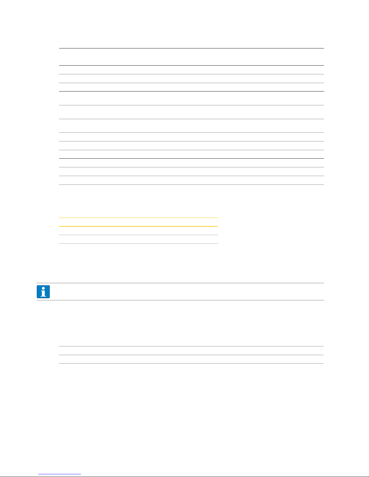
+ 1
– 2
10 –
7 +
12 –
11 +
0/4...20 mA
III III
3
HART®
GN
I
?
?
?
HHT
PowerPwr
1
+ 1
2
– 3
+ 2
– 3
HART®
HART®
210 Ω
1
0/4...20 mA
(source)
RL ≤ 500 Ω
Fig. 1: Block diagram of the IM33-11Ex-Hi/24VDC
Hans Turck GmbH & Co. KG • Tel. +49 208/4952-0 • Fax +49 208/4952-264
12
Safety Manual – Isolating Transducers
+ 1
– 2
10 –
7 +
12 –
11 +
0/4...20 mA
III III
3
HART®
GN
I
?
?
?
HHT
PowerPwr
1
+ 1
2
– 3
+ 2
– 3
HART®
HART®
210 Ω
1
0/4...20 mA
(source)
RL ≤ 500 Ω
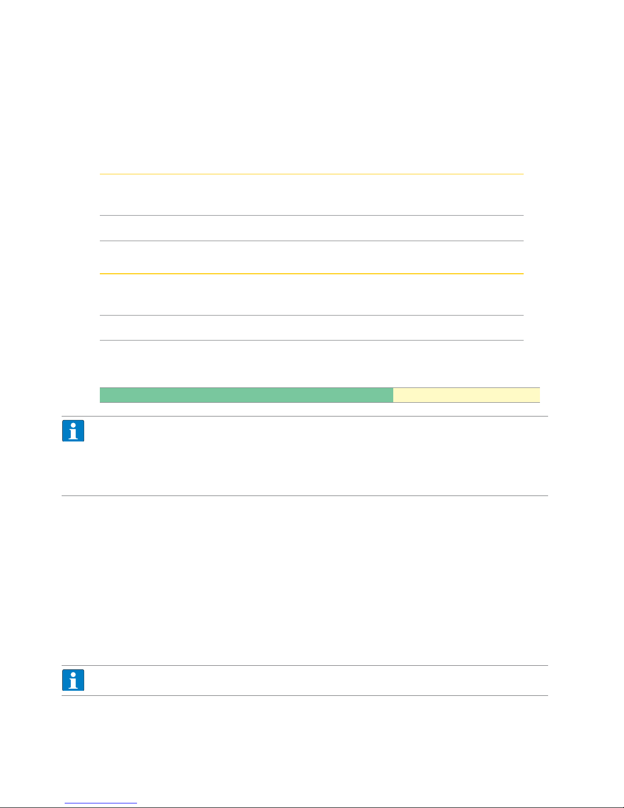
Fig. 2: Block diagram of the IM33-11-Hi/24VDC
+ 1
– 2
10 –
7 +
12 –
11 +
III III
3
9 –
8 +
HART®
GN
I
?
?
?
1
210 Ω
1
2
0/4...20 mA
(source)
RL ≤ 500 Ω
0/4...20 mA
(source)
RL ≤ 500 Ω
HHT
PowerPwr
+ 1
2
– 3
+ 2
– 3
HART®
HART®
0/4...20 mA
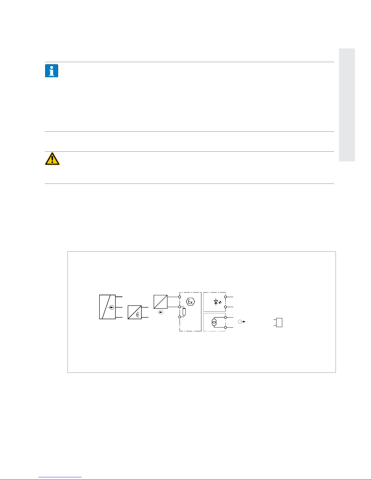
Fig. 3: Block diagram of the IM33-12Ex-Hi/24VDC
+ 1
– 2
10 –
7 +
12 –
11 +
0/4...20 mA
III III
3
+ 4
– 5
6
9 –
8 +
HART®
GN
I
?
I
?
?
?
?
?
1
2
HART®
210 Ω
210 Ω
1
2
0/4...20 mA
(source)
RL ≤ 500 Ω
0/4...20 mA
(source)
RL ≤ 500 Ω
HHTHHT
PowerPwr
+ 1
2
– 3
+ 4
5
– 6
+ 2
– 3
+ 5
– 6
HART®
HART®
HART®
HART®
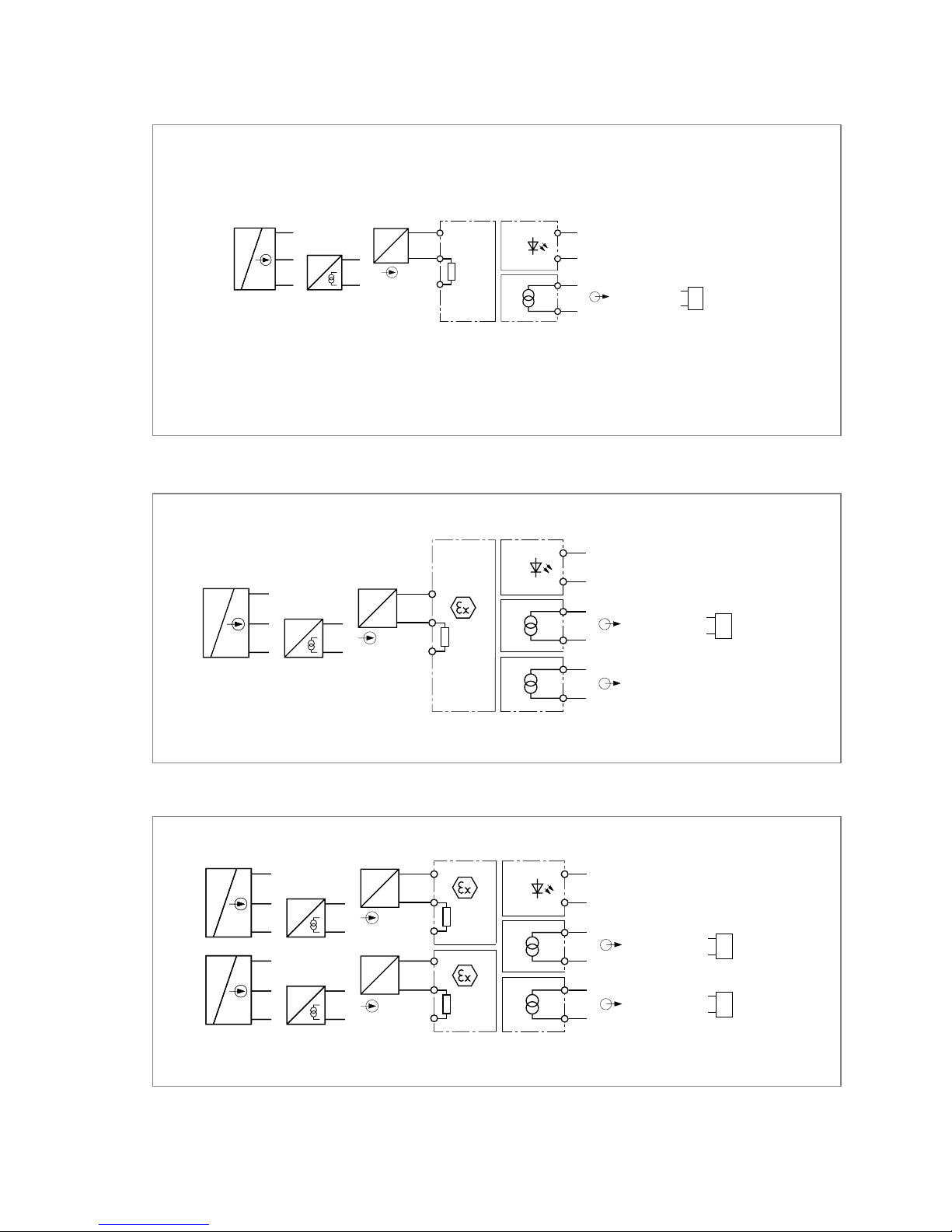
Fig. 4: Block diagram of the IM33-22Ex-Hi/24VDC
 Loading...