

turck HART IM33-11-Hi/24VDC, HART IM33-22-Hi/24VDC Series, HART IM33-12-Hi/24VDC Series Series Manual

DE / EN .................................. Seite/page 1…6
FR / PT ............................. Page/página 7…12
HART®-Messumformer-Speisetrenner
IM33-11…-Hi/24VDC
IM33-12…-Hi/24VDC
IM33-22…-Hi/24VDC
GEFAHR
ì
Die vorliegende Anleitung enthält keine Informationen zum Einsatz in
sicherheitsgerichteten Anwendungen.
Lebensgefahr durch Fehlanwendung!
➤
Bei Einsatz in sicherheitsgerichteten Systemen: Halten Sie unbedingt
die Vorschriften des zugehörigen Sicherheitshandbuchs ein.
Gerätekurzbeschreibung
Die Geräte sind für den Einbau in industrielle Großanlagen und Großwerkzeuge bestimmt.
• Messumformer-Speisetrenner mit bidirektionaler HART®-Übertragung
IM33-11…-Hi…: einkanalig
IM33-12…-Hi…: einkanalig mit zwei galvanisch getrennten Ausgängen
IM33-22…-Hi…: zweikanalig
• Anschluss von
– HART®-Zweidraht-Messumformern: Versorgung und Signalübertra-
gung
– aktiven HART®-Zweidraht-Signalquellen: Das aktive Stromsignal
0/4…20 mA wird dem passiven Eingang zugeführt und übertragen
– HART®-Dreidraht-Messumformern: Versorgung und Signalübertra-
gung
• Signalbereich 0/4…20 mA
• Galvanische Trennung der Ein- und Ausgangskreise zueinander, unterein-
ander und zur Versorgung
• Kurzschlussfeste Eingangskreise
• Konstante Spannung am Messumformer von 17 V
• Übertragungsverhältnis 1:1
• Abziehbare Klemmenblöcke
• Unterbrechungsfreier Anschluss eines HART®-Kommunikators über Prüf-
buchsen in den Klemmenblöcken
• Bei Geräten mit „Ex“ in der Typenbezeichnung:
– Eingangskreise eigensicher Ex ia
– Anwendungsbereich nach ATEX: II (1) G, II (1) D, II 3 G
– Zugelassen für Einbau in Zone 2
HART® isolating transducer
IM33-11…-Hi/24VDC
IM33-12…-Hi/24VDC
IM33-22…-Hi/24VDC
DANGER
ì
These instructions do not provide any information on use in safety-related
applications.
Danger to life due to misuse!
➤
When using in safety-related systems: Observe the instructions provided in the relevant safety manual.
Short description
The devices are designed for installation in large-scale industrial installations and equipment.
• Isolating transducer with bidirectional HART® transmission
IM33-11…-Hi…: one channel
IM33-12…-Hi…: one channel with two galvanically isolated outputs
IM33-22…-Hi…: two channels
• Connection of
– 2-wire HART® transducers: supply and signal transmission
– active 2-wire HART® signal sources: the active current signal
0/4…20 mA is transferred to the passive input
– 3-wire HART® transducers: supply and signal transmission
• Signal range 0/4…20 mA
• Galvanic isolation between individual inputs and outputs and supply
• Short-circuit protected input circuit
• Constant transducer voltage of 17 V
• Transmission characteristic 1:1
• Removeable terminal blocks
• Direct connection of a HART® communicator via test sockets in the
terminal block
• With devices with “Ex” in the type
designation:
– Intrinsically safe input circuits Ex ia
– Area of application acc. to ATEX: II (1) G, II (1) D, II 3 G
– Approved for installation in zone 2
1 / 12

IM33-…-Hi/24VDC
LED-Anzeigen (Fig. 1…6)
Pwr grün Betriebsbereitschaft
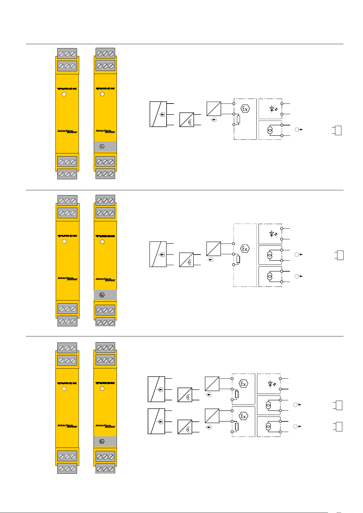
Klemmenbelegung (Fig. 2 + 4 + 6)
IM33-11…-Hi…
1 – 3 Eingangskreis (bei Geräten mit „Ex“ in der Typenbezeichnung ist
der Eingangskreis eigensicher)
1, 2 Zweidraht-Messumformer mit Versorgung und HART®-Übertra-
gung (III)
2, 3 passiver Zweidraht-Eingang für aktive Stromsignale und HART®-
Übertragung (II)
1, 2, 3 Dreidraht-Messumformer mit Versorgung und HART®-Übertra-
gung (I)
7, 10 aktiver Stromausgang
11, 12 Betriebsspannungsanschluss 24 VDC: 19…29 VDC, ≤ 3 W
IM33-12…-Hi…
1 – 3 Eingangskreis (bei Geräten mit „Ex“ in der Typenbezeichnung ist
der Eingangskreis eigensicher)
1, 2 Zweidraht-Messumformer mit Versorgung und HART®-Übertra-
gung (III)
2, 3 passiver Zweidraht-Eingang für aktive Stromsignale und HART®-
Übertragung (II)
1, 2, 3 Dreidraht-Messumformer mit Versorgung und HART®-Übertra-
gung (I)
7, 10 aktiver Stromausgang
8, 9 aktiver Stromausgang
11, 12 Betriebsspannungsanschluss 24 VDC: 19…29 VDC, ≤ 3 W
IM33-22…-Hi…
1 – 3 Eingangskreis Kanal 1 (bei Geräten mit „Ex“ in der Typenbezeich-
nung ist der Eingangskreis eigensicher)
1, 2 Zweidraht-Messumformer mit Versorgung und HART®-Übertra-
gung (III)
2, 3 passiver Zweidraht-Eingang für aktive Stromsignale und HART®-
Übertragung (II)
1, 2, 3 Dreidraht-Messumformer mit Versorgung und HART®-Übertra-
gung (I)
4 – 6 Eingangskreis Kanal 2 (bei Geräten mit „Ex“ in der Typenbezeich-
nung ist der Eingangskreis eigensicher)
4, 5 Zweidraht-Messumformer mit Versorgung und HART®-Übertra-
gung (III)
5, 6 passiver Zweidraht-Eingang für aktive Stromsignale und HART®-
Übertragung (II)
4, 5, 6 Dreidraht-Messumformer mit Versorgung und HART®-Übertra-
gung (I)
7, 10 aktiver Stromausgang Kanal 1
8, 9 aktiver Stromausgang Kanal 2
11, 12 Betriebsspannungsanschluss 24 VDC: 19…29 VDC, ≤ 3 W
LED indications (Fig. 1…6)
Pwr green power on
Terminal configuration (Fig. 2 + 4 + 6)
IM33-11…-Hi…
1 – 3 input circuit (the input circuit is intrinsically safe on devices with
“Ex” in the type designation)
1, 2 two-wire transducer with supply and HART® transmission (III)
2, 3 passive two-wire input for active current signals and HART®
transmission (II)
1, 2, 3 three-wire transducer with supply and HART® transmission (I)
7, 10 active current output
11,12 supply voltage connection 24 VDC: 19…29 VDC, ≤ 3 W
IM33-11…-Hi…
1 – 3 input circuit (the input circuit is intrinsically safe on devices with
“Ex” in the type designation)
1, 2 two-wire transducer with supply and HART® transmission (III)
2, 3 passive two-wire input for active current signals and HART®
transmission (II)
1, 2, 3 three-wire transducer with supply and HART® transmission (I)
7, 10 active current output
8, 9 active current output
11,12 supply voltage connection 24 VDC: 19…29 VDC, ≤ 3 W
IM33-22…-Hi…
1 – 3 input circuit channel 1 (the input circuit is intrinsically safe on
devices with “Ex” in the type designation)
1, 2 two-wire transducer with supply and HART® transmission (III)
2, 3 passive two-wire input for active current signals and HART®
transmission (II)
1, 2, 3 three-wire transducer with supply and HART® transmission (I)
4 – 6 input circuit channel 2 (the input circuit is intrinsically safe on
devices with “Ex” in the type designation)
4, 5 two-wire transducer with supply and HART® transmission (III)
5, 6 passive two-wire input for active current signals and HART®
transmission (II)
4, 5, 6 three-wire transducer with supply and HART® transmission (I)
7, 10 active current output channel 1
8, 9 active current output channel 2
11,12 supply voltage connection 24 VDC: 19…29 VDC, ≤ 3 W
Connection via lifting cages with captive screws, connection prole:
≤ 1 × 2.5 mm2, 2 × 1.5 mm2 or 2 × 1 mm2 with wire sleeves, max. tightening
torque: 0.5 Nm, test sockets Ø 2 mm
Leitungsanschluss durch anhebende Käge mit unverlierbaren Schrauben,
Anschlussquerschnitt: ≤ 1 × 2,5 mm2, 2 × 1,5 mm2 oder 2 × 1 mm2 mit AderEndhüsen, max. Anzugsdrehmoment: 0,5 Nm, Prüfbuchsen Ø 2 mm
2 / 12
IM33-…-Hi/24VDC
IM33-11Ex-Hi
24VDC
Zone 2: Do not disconnect when live!
546
213
Pwr
1110
IM33-12Ex-Hi
24VDC
12
879
Zone 2: Do not disconnect when live!
546
213
Pwr
1110
IM33-22Ex-Hi
24VDC
12
879
Zone 2: Do not disconnect when live!
Fig. 2Fig. 1
III III
HART®
?
*) nur Ex-Gerät
only Ex device
Fig. 4Fig. 3
+ 1
– 3
2
0/4...20 mA
HART®
?
+ 2
– 3
HART®
?
GN
11 +
12 –
7 +
10 –
PowerPwr
0/4...20 mA
1
(source)
RL ≤ 500 Ω
HHT
+ 1
I
– 2
1
*)
210 Ω
3
III III
+ 2
– 3
HART®
?
1
+ 1
I
– 2
*)
210 Ω
3
HART®
?
+ 1
– 3
HART®
2
?
0/4...20 mA
GN
11 +
12 –
7 +
10 –
8 +
9 –
PowerPwr
0/4...20 mA
1
(source)
RL ≤ 500 Ω
0/4...20 mA
(source)
2
RL ≤ 500 Ω
HHT
*) nur Ex-Gerät
only Ex device
Fig. 6Fig. 5
III III
HART®
?
+ 1
HART®
2
?
– 3
HART®
+ 4
?
HART®
5
?
– 6
0/4...20 mA
+ 2
– 3
+ 5
– 6
HART®
?
1
HART®
?
2
GN
11 +
12 –
7 +
10 –
8 +
9 –
PowerPwr
0/4...20 mA
1
(source)
RL ≤ 500 Ω
0/4...20 mA
(source)
2
RL ≤ 500 Ω
HHTHHT
+ 1
*)
I
– 2
210 Ω
3
+ 4
*)
I
– 5
210 Ω
6
*) nur Ex-Gerät
only Ex device
3 / 12

IM33-…-Hi/24VDC
Allgemeine Hinweise
Aufgrund des 1:1-Übertragungsverhaltens werden Drahtbrüche im
Eingangskreis als Ausgangsstrom von 0 mA und Kurzschlüsse als Ausgangsstrom von > 22 mA ausgegeben.
Die digitalen Signale der HART®-Kommunikation werden bidirektional
übertragen. Der HART®-Kommunikator kann im Ein- und Ausgangskreis
angeschlossen werden.
Hinweise nur für Geräte mit „Ex“ in der Typenbezeichnung
Beachten Sie beim Anschluss des HART®-Kommunikators im Eingangskreis
die Forderungen der Zündschutzart „Eigensicherheit“ (z. B. Nachweis der
Eigensicherheit).
Für den Anschluss von aktiven Stromsignalen an den passiven Eingang sind
die angegebenen Werte aus der EG-Baumusterprüfbescheinigung an den
Klemmen 2, 3 bzw. 5, 6 gültig.
Bei Einbau in Zone 2 muss das Gerät in ein Gehäuse nach EN 60079-0 mit
einer Schutzart mindestens IP54 nach IEC/EN 60529 montiert werden.
Bei Einbau in Zone 2 ist das Verbinden und Trennen der Anschlüsse von
nicht eigensicheren Stromkreisen unter Spannung nur zulässig, wenn keine
explosionsfähige Atmosphäre vorliegt.
Für den Versorgungsstromkreis sind externe Maßnahmen zu treen, die verhindern, dass die Bemessungsspannung durch vorübergehende Störungen
um mehr als 40 % überschritten wird.
Bei der Verdrahtung mit Litzendrähten müssen die Drahtenden unbedingt
mit Aderendhülsen fest xiert werden.
Das Gerät darf in einem Bereich mit einem Verschmutzungsgrad von nicht
größer als 2 eingesetzt werden.
General indications
Due to the 1:1 transfer mode a wire-break in the input circuit is indicated
by an output current of 0 mA; short-circuit conditions are signalled by an
output current of > 22 mA.
The digital HART® communication signals are transferred bidirectionally.
The HART® communicator may be connected to the input and output
circuits.
Notes only for devices with “Ex” in the type designation
When connecting the Hart® communicator to the input circuit, please
observe the requirements of protection type "intrinsic safety" (e.g. proof of
intrinsic safety).
When connecting active current signals to the passive input the data that
have been taken from the EC examination certicate at terminals 2 and 3 or
5 and 6 is valid.
For installation in zone 2 the device must be installed in a housing which
complies with the requirements of EN 60079-0 with a minimum protection
degree of IP54 according to IEC/EN 60529.
With mounting in zone 2 the connecting and disconnecting of energized
non intrinsically safe circuits is only permitted in non-explosive atmosphere.
For the power supply external measures are to be taken to prevent that the
rated voltage is exceeded by transient faults by more than 40 %.
When wiring the braids, always use end sleeves for rm connection.
The device may be used in an area with a pollution degree not greater than 2.
Montage und Installation (Fig. 7)
Das Gerät ist aufschnappbar auf Hutschiene (EN 60715) oder aufschraubbar
auf Montageplatte. Geräte gleichen Typs können direkt aneinander gesetzt
werden. Sorgen Sie für eine ausreichende Wärmeabfuhr.
Führen Sie die Montage und Installation den gültigen Vorschriften entsprechend durch. Dafür sind Sie als Betreiber verantwortlich.
Die abziehbaren Klemmenblöcke sind codiert und können nur auf den
vorgesehenen Sockel gesteckt werden. Dabei weisen die Ex-Klemmen die
gleiche Codierung auf. Die Codierung darf nicht verändert oder beschädigt
werden.
Schützen Sie das Gerät ausreichend gegen Staub, Schmutz, Feuchtigkeit
und andere Umwelteinüsse. Auch gegen energiereiche Strahlung, Risiken
mechanischer Beschädigung, unbefugter Veränderung und zufälliger
Berührung müssen Vorkehrungen getroen werden. Die Geräte erfüllen
ausschließlich die EMV-Anforderungen für den industriellen Bereich und
sind nicht zum Einsatz in Wohngebieten geeignet.
Entsorgung
Die Geräte sind fachgerecht zu entsorgen und nicht als normaler Abfall.
Mounting and installation (Fig. 7)
The device is suited for snap-on clamps for hat rail mounting (EN 60715)
or for screw panel mounting. Devices of the same type may be mounted
directly next to each other. It must be ensured that heat is conducted away
from the device.
Mounting and installation must be carried out in accordance with the applicable regulations. The operator is responsible for compliance with the
regulations.
The removeable terminal blocks are coded and may only be plugged into
the designated sockets. The Ex terminals have the same coding. The coding
system may not be altered or damaged.
The device must be protected against dust, dirt, moisture and other environmental inuences as well as against strong electro-magnetic emissions.
It should also be protected against the risks of mechanical damaging,
unauthorised access and incidental contact. The devices only meet the EMC
requirements for industrial areas and are not suitable for use in residential
areas.
Disposal
The devices must be disposed of correctly and must not be included in
normal household garbage.
4 / 12
 Loading...