

turck FXDP Series, FXDP-IM8-0001, FXDP-IM16-0001, FXDP-OM8-0001, FXDP-IOM88-0001 User Manual
...Page 1

FXDP –
USER MANUAL
Page 2

All brand and product names ar e trademarks or registered trade
marks of the owner concerned.
3rd, revised edition, 09/05
© Hans Turck GmbH & Co. KG, Mülheim an der Ruhr
All rights reserved, including those of the translation.
No part of this manual may be reproduced in any form (printed,
photocopy, microfilm or any other process) or processed, duplicated or distributed by means of electronic systems without written
permission of Hans Turck GmbH & Co. KG, Mülheim an der Ruhr.
Subject to alterations without notice.
Page 3

Warning!
Dangerous electrical voltage!
Before commencing the installation
Disconnect the power supply of the device.
Ensure that devices cannot be accidentally restarted.
Verify isolation from the supply.
Earth and short circuit.
Cover or enclose neighboring units that are live.
Follow the engineering instructions of the device concerned.
Only suitably qualified personnel in accordance with EN 50 110-
1/-2 (VDE 0 105 Part 100) may work on this device/system.
Before installation and before touching the device ensure that
you are free of electrostatic charge.
The functional earth (FE) must be connected to the protective
earth (PE) or to the potential equalization. The system installer is
responsible for implementing this connection.
Connecting cables and signal lines should be installed so that
inductive or capacitive interference do not impair the automation
functions.
Install automation devices and related operating elements in
such a way that they are well protected against unintentional
operation.
Suitable safety hardware and software measures should be
implemented for the I/O interface so that a line or wire breakage
on the signal side does not result in undefined states in the auto
mation devices.
Ensure a reliable electrical isolation of the low voltage for the 24
volt supply. Only use power supply units complying with IEC 60
364-4-41 (VDE 0 100 Part 410) or HD 384.4.41 S2.
Deviations of the mains voltage from the rated value must not
exceed the tolerance limits given in the specifications, otherwise
this may cause malfunction and dangerous operation.
Emergency stop devices complying with IEC/EN 60 204-1 must
be effective in all operating modes of the automation devices.
Unlatching the emergency-stop devices must not cause restart.
-
I
Page 4

Devices that are designed for mounting in housings or control
cabinets must only be operated and controlled after they have
been installed with the housing closed. Desktop or portable units
must only be operated and controlled in enclosed housings.
Measures should be taken to ensure the proper restart of
programs interrupted after a voltage dip or failure. This should
not cause dangerous operating states even for a short time. If
necessary, emergency-stop devices should be implemented.
Wherever faults in the automation system may cause damage to
persons or property, external measures must be implemented to
ensure a safe operating state in the event of a fault or malfunction (for example, by means of separate limit switches, mechanical interlocks etc.).
The electrical installation must be carried out in accordance with
the relevant regulations (e. g. with regard to cable cross
sections, fuses, PE).
All work relating to transport, installation, commissioning and
maintenance must only be carried out by qualified personnel.
(IEC 60 364 and HD 384 and national work safety regulations).
All shrouds and doors must be kept closed during operation.
II
Page 5

Table of Contents
About this manual
Documentation concept................................................................................0-2
General Information. .....................................................................................0-3
Prescribed Use........................................................................................ 0-3
Notes Concerning Planning /Installation of this Product ........................0-3
Description of Symbols Used ......................................................................0-4
List of Revisions............................................................................................0-5
1 The FXDP product family
General information....................................................................................... 1-3
Product overview .........................................................................................1-4
The service module ................................................................................. 1-5
Connection to PROFIBUS-DP ......................................................................1-6
Addressing on PROFIBUS-DP ................................................................ 1-6
Transmission rates .................................................................................. 1-6
Bus termination ....................................................................................... 1-6
Configuration files ...................................................................................1-7
Connection possibilities................................................................................1-8
PROFIBUS-DP ........................................................................................ 1-8
Operating- / load voltage ........................................................................1-8
In-/ and outputs.......................................................................................1-9
General technical data ................................................................................ 1-10
Technical data.......................................................................................1-10
Dimension drawings..............................................................................1-12
LED indications .....................................................................................1-12
Diagnosis .................................................................................................... 1-13
2 Digital Input Modules
Digital input module, 8-channel....................................................................2-2
FXDP-IM8-0001....................................................................................... 2-2
Digital input module, 16-channel.................................................................. 2-6
FXDP-IM16-0001..................................................................................... 2-6
D300720 0905 - FXDP i
Page 6

3 Digital Output Modules
Digital output module, 8-channel.................................................................. 3-2
FXDP-OM8-0001.....................................................................................3-2
Digital output module, 16-channel................................................................3-6
FXDP-OM16-0001...................................................................................3-6
4 Digital Hybrid Modules
Digital hybrid module, 2 x 8-channel, I/I or O/O per connector.................... 4-2
FXDP-IOM88-0001..................................................................................4-2
Digital combined module, 2 x 8-channel, I/O per connector........................4-7
FXDP-CSG88-0001.................................................................................4-7
5 Universal Service Module
FXDP-XSG16-0001....................................................................................... 5-2
The service module ................................................................................. 5-2
Block diagram .........................................................................................5-4
Wiring diagrams ......................................................................................5-5
Technical data.........................................................................................5-6
Configuration options..............................................................................5-7
Parameterization .....................................................................................5-8
Diagnosis................................................................................................. 5-9
6 Connection to a Siemens PLC S7
General..........................................................................................................6-2
Reading- in the GSD File .............................................................................. 6-3
Selecting the FXDP Modules as Slaves........................................................6-5
Configuring the FXDP modules............................................................... 6-6
Diagnostic messages in the process image............................................ 6-7
Parameterization of the FXDP modules ........................................................6-8
Diagnosis evaluation on a S7-PLC ...............................................................6-9
Online diagnosis with die SIMATIC Manager.......................................... 6-9
Diagnosis via function block FB125...................................................... 6-12
7 Appendix
Declaration of conformity..............................................................................7-2
8Glossary
D300720 0905 - FXDPii
Page 7

9Index
D300720 0905 - FXDP iii
Page 8

D300720 0905 - FXDPiv
Page 9

About this manual
Documentation concept .................................................................... 2
General Information........................................................................... 3
Prescribed Use............................................................................................3
Notes Concerning Planning /Installation of this Product ............................3
Description of Symbols Used ............................................................ 4
List of Revisions ................................................................................ 5
D300720 0905 - FXDP 0-1
Page 10

About this manual
Documentation concept
This manual contains all information about the TURCK product
family FXDP in protection class IP67.
The following chapters contain exact information about the general
technical data and properties of each single module in the product
family, a description of the coupling to PROFIBUS-DP as well as
information about diagnosis and data mapping.
D300720 0905 - FXDP0-2
Page 11
General Information.
General Information.
Attention
Please read this section carefully. Safety aspects cannot be left to
chance when dealing with electrical equipment.
Prescribed Use
Warning
The devices described in this manual must be used only in applications prescribed in this manual or in the respective technical descriptions, and only with certified components and devices from
third party manufacturers.
Appropriate transport, storage, deployment and mounting as well as
careful operating and thorough maintenance guarantee the troublefree and safe operation of these devices.
Notes Concerning Planning /Installation of this Product
Warning
All respective safety measures and accident protection guidelines
must be considered carefully and without exception.
D300720 0905 - FXDP 0-3
Page 12
About this manual
Description of Symbols Used
Warning
This sign can be found next to all notes that indicate a source of ha zards. This can refer to danger to personnel or damage to the system
(hardware and software) and to the facility.
This sign means for the operator: work with extreme caution.
Attention
This sign can be found next to all notes that indicate a potential hazard.
This can refer to possible danger to personnel and damages to the
system (hardware and software) and to the facility.
Note
This sign can be found next to all general notes that supply important information about one or more operating steps. These specific
notes are intended to make operation easier and avoid unnecessary
work due to incorrect operation.
D300720 0905 - FXDP0-4
Page 13

List of Revisions
List of Revisions
In comparison to the previous manual edition, the following
changes/ revisions have been made
Table 1:
List of revisions
Chapter Subject/
new changed
Description
Chap. 5 – Example for wire break detection X
D300720 0905 - FXDP 0-5
Page 14

About this manual
D300720 0905 - FXDP0-6
Page 15

1 The FXDP product family
General information........................................................................... 3
Product overview .............................................................................. 4
The service module .....................................................................................5
Connection to PROFIBUS-DP............................................................. 6
Addressing on PROFIBUS-DP ....................................................................6
Transmission rates ......................................................................................6
Bus termination ...........................................................................................6
Configuration files .......................................................................................7
Connection possibilities .................................................................... 8
PROFIBUS-DP ............................................................................................8
Operating- / load voltage ............................................................................8
In-/ and outputs...........................................................................................9
General technical data .................................................................... 10
Technical data...........................................................................................10
Dimension drawings..................................................................................12
LED indications .........................................................................................12
Diagnosis ......................................................................................... 13
D300720 0905 - FXDP 1-1
Page 16

The FXDP product family
This chapter contains all information about the construction and the
general technical data of the FXDP modules as well as about the
their method of functioning.
Note
Please find all module-specific information in the module descriptions contained in the respective module chapters of the manual.
D300720 0905 - FXDP1-2
Page 17
General information
General information
The new FXDP product family shows the following proven module
properties:
rugged PROFIBUS-DP module
glass-fibre reinforced plastic housing
fully encapsulated electronics
degree of protection IP67
galvanic channel isolation to the PROFIBUS-DP
short-circuit protected channels
Figure 1:
FXDP module
1
Note
All modules of the product family FXDP are approved for use in
Zone 2.
D300720 0905 - FXDP 1-3
Page 18

The FXDP product family
Product overview
Table 2:
Product overview
of the FXDP family
User data
section
8 Bit IN
16 Bit IN x x I/I per connector
8 Bit OUT x x O per connector
16 Bit OUT x x O/O per connector
8 Bit IN,
8 Bit OUT
8 Bit IN,
8 Bit OUT
8 Bit IN,
8 Bit DIAG
8 Bit OUT,
8 Bit DIAG
12 Bit IN,
4 Bit OUT
n Bit IN,
16-n Bit OUT
(AUTO Mode)
FXDP-IM8-0001
FXDP-IM16-0001
x
FXDP-OM8-0001
FXDP-OM16-0001
FXDP-IOM88-0001
x x I/I or O/O per
Comment
FXDP-CSG88-0001
FXDP-XSG16-0001
x I per connector
connector
x x I/O per connector
x I/DIAG per connector
x O/DIAG per
connector
x I/I or O/O per
connector
x outputs are read back
n Bit IN,
16-n Bit OUT
(PROG Mode)
AddOn:
Diag mapped
x channel as IN,
inverted IN, DIAG IN
or OUT
x x x x x x x diagnostics mapped
to user data section
D300720 0905 - FXDP1-4
Page 19

Product overview
The service module
Besides the typical FXDP properties like the extended diagnosis, the
possibility of diagnosis-data mapping into the user data as well as
the comfortable M12-I/O-connection technology, the service
module FXDP-XSG16-0001 provides the following additional
features:
Each single channel can be configured according to the applica-
tion via configuration software tools (e.g. SIMATIC Manager,
etc.). The required combination of in- and outputs can be exactly
planned to suit the customer’s needs. This thus ensures a 100%
technology utilization and a cost minimization.
Operating FXDP-modules can directly be replaced by the XSG-
module. Without any additional configuration, it can take-over
the function of the module that has to be replaced. The customer
only has to change the hardware, to set the previously config
ured PROFIBUS-DP address at the XSG-module and to execute
a voltage reset at the module.
Based on this fact, the module is universally applicable and can be
used to reduce inventory costs and system down-times - two
factors that are constantly gaining in importance in face of ever more
complex technical processes.
-
1
D300720 0905 - FXDP 1-5
Page 20

The FXDP product family
Connection to PROFIBUS-DP
Addressing on PROFIBUS-DP
The PROFIBUS-DP address (1 to 126) is set via three decimal rotary
coding switches located under a transparent protective cover.
Figure 2:
Setting the
PROFIBUS-DP
address
X 10
3
2
1
4
0
9
5
6
7
8
X 1
3
2
1
4
0
9
5
6
7
8
SF
X 100
1
0
SF
Transmission rates
The module supports transmission rates of up to 12 Mbps and
adjusts automatically to the transmission speed determined by the
master.
Bus termination
The bus termination is realized via an external terminating resistor at
Bus-OUT.
D300720 0905 - FXDP1-6
Page 21

Connection to PROFIBUS-DP
Table 3:
Configuration files
Configuration files
The configuration files for the software link are available via the
internet under
www.turck.com for download purposes.
The following table shows the corresponding configuration files for
each single module:
Module Configuration file
FXDP-IM8-0001 TU0_ff1f.gsd
FXDP-IM16-0001 TU1_ff1f.gsd
FXDP-OM8-0001 TU2_ff1f.gsd
FXDP-OM16-0001 TU3_ff1f.gsd
FXDP-IOM88-0001 TU4_ff1f.gsd
FXDP-CSG88-0001 TU5_ff1f.gsd
FXDP-XSG16-0001 TU6_ff1f.gsd
1
D300720 0905 - FXDP 1-7
Page 22
The FXDP product family
3
Connection possibilities
PROFIBUS-DP
Module connection to the PROFIBUS-DP is established via two
reverse-keyed M12 connectors.
Figure 3:
M12x1-connector
for connection to
PROFIBUS-DP
Figure 4:
7/8” connector for
supplying and
feeding through of
supply voltage
Male (IN)
2
4
1 =N.N.
2 = A line
3 = GND
13
4 = B line
5 = Shield
5
Female (OUT)
1 = 5 VDC
2
2 = A line
1
3 = GND
4 = B line
5
4
5 = Shield
Operating- / load voltage
The module is powered via a 7/8” connector. The power is fed
through via a second 7/8” connector.
Male (Ui)
3
4
1 = GND
2
2 = GND
Female (Uo)
3
2
4
3 = PE
5
1
4 = U
5 = U
B
L
1
5
Note
The operational voltage is monitored internally. Supply failures of
less than 2.5 ms are compensated and thus do not lead to module
malfunction. It is also ensured that a voltage reset cannot lead to
generation of faulty signals.
D300720 0905 - FXDP1-8
Page 23

Connection possibilities
In-/ and outputs
The module is equipped throughout with 5-pole metal M12connectors for connection of the sensor/actuator level.
Note
For the pin assignment, please refer to the wiring diagrams in the
module-specific chapters of the manual.
1
D300720 0905 - FXDP 1-9
Page 24

The FXDP product family
General technical data
Technical data
Table 4:
General technical
data of FXDP
modules
A In case of low
simultaneity factors
and low ambient
temperatures,
mounting distances
of <
50mm may be
possible.
Power supply
Operational voltage UB24 VDC (18 ... 30 VDC)
Load voltage U
L
Internal current
consumption (via U
24 VDC (18 ... 30 VDC)
< 70 mA
)
B
Connections nickel-plated brass connectors
PROFIBUS-DP 1 x male M12 connector (IN),
1 x female M12 connector (OUT),
5-pole, reverse-keyed
Power supply 1 x 7/8” male connector (Ui),
1 x 7/8” female connector (Uo),
5-pole
Inputs/outputs female M12-connectors, 5-pole
Housing PA6-GF30
Dimensions 220,5 x 60,4 x 27 mm (H x B x T)
Mounting via 4 through-holes Ø 5.4 mm
Mounting distance
module/module
min. ≥ 50 mm A
Valid for operation in the ambient
temperatures mentioned below,
with sufficient ventilation as well
as maximum load (horizontal
mounting).
Degree of protection
IP67
(IEC 60529/EN 60529)
Vibration resistance test according to
EN 60068-2-6,
IEC 68-2-47
D300720 0905 - FXDP1-10
Page 25

General technical data
Shock resistance test according to
EN 60068-2-27
EMC according to
EN 61000-6-2,
EN 61000-6-4
Approval for use in
Zone 2
Temperature range
–Operating
temperature
– Storage and
transport
to EN 50014/2000,
EN 50021/2000 /
É II 3 G EEx nA IIC T4 X
0 °C to +55 °C
(+32 °F to +131 °F)
-25 °C to +70 °C
(-13 °F to +158 °F)
1
D300720 0905 - FXDP 1-11
Page 26
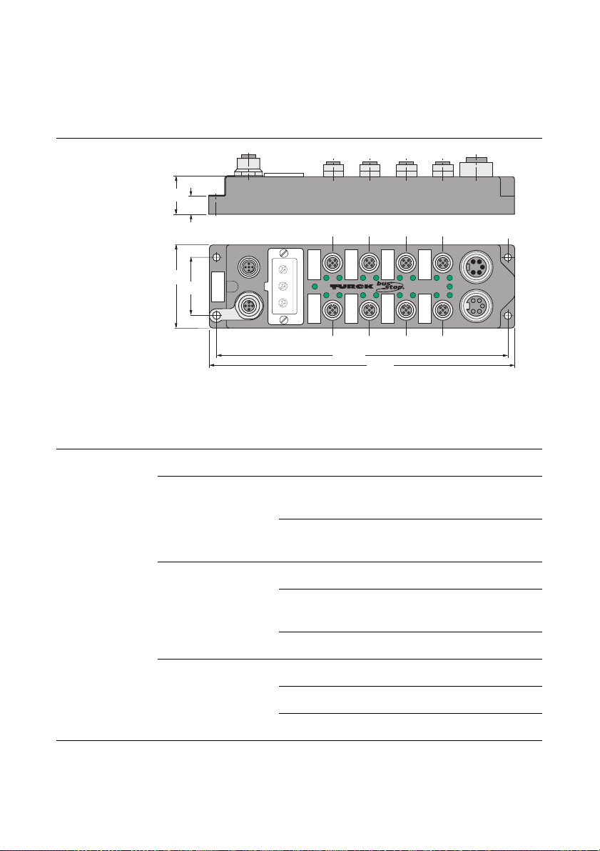
The FXDP product family
Dimension drawings
Figure 5:
FXDP moduledimensions
27
13
Table 5:
FXDP
LED indications
60,4
C3 C2 C1 C0
In
0
SF
1
SF
x100 x10 x1
0
1
9
Bus
2
8
7
3
4
6
42
5
0
1
9
8
2
7
3
4
6
5
Out
2
3
6
7
1
FXDP-CSG88-0001
5
0
Power
4
ø 5,4
U
i
U
0
C7 C6 C5 C4
210,5
220,5
LED indications
LED Color Meaning
Bus green communication with PROFIBUS-
DP running
red no communication to
PROFIBUS-DP
Power off UB < 18 VDC
green UB and UL,
within the operating range
red UL < 18 VDC
In-/ outputs off not actuated, inactive
green actuated, active
red channel overload
D300720 0905 - FXDP1-12
Page 27

Diagnosis
Diagnosis
1
These modules combine the advantages of channel diagnostics - as
known from the PDP series - with the favorable compact housing
dimensions of the FLDP series.
Output diagnostics are effective for each channel, whereas the
sensor supply is monitored separately for each connector.
Diagnostic data are also transferred to the PROFIBUS-DP and the
respective status is indicated via LEDs on the module individually for
each channel.
Diagnostic data can also be reproduced and transferred within the
user data area.
Note
Please read the corresponding sections in the module-specific
chapters for any information about the diagnosis mapping in the
process data image.
Channel-related diagnostics help increase system availability,
because the type of error and its location can be determined in
detail. According to PROFIBUS specifications, all diagnostic data
are transferred to the higher level control system via the PROFIBUSDP where these information can be evaluated by higher level
masters.
Chapter 6 of this manual „Connection to a Siemens PLC S7”
contains an example for plain-text diagnosis evaluation.
D300720 0905 - FXDP 1-13
Page 28

The FXDP product family
D300720 0905 - FXDP1-14
Page 29

2 Digital Input Modules
Digital input module, 8-channel......................................................... 2
FXDP-IM8-0001...........................................................................................2
– Wiring diagram ........................................................................................3
– Technical data .........................................................................................3
– Parameterization ......................................................................................4
– Diagnosis .................................................................................................5
Digital input module, 16-channel....................................................... 6
FXDP-IM16-0001.........................................................................................6
– Wiring diagram ........................................................................................7
– Technical Data .........................................................................................7
– Parameterization ......................................................................................8
– Diagnosis .................................................................................................9
D300720 0905 - FXDP 2-1
Page 30
Digital Input Modules
Digital input module, 8-channel
FXDP-IM8-0001
The busstop® input station FXDP-IM8-0001 is a modular
PROFIBUS-DP slave in a compact housing design.
The module is suited for connection of up to eight 2/3 wire pnp
sensors or mechanical contacts.
Figure 6:
FXDP-IM8-0001
D300720 0905 - FXDP2-2
Page 31

Digital input module, 8-channel
Wiring diagram
Figure 7:
Wiring diagram
Table 6:
Technical data
FXDP-IM8-0001
3 () BU
5
PE
4 ( ) BK
1 (+) BN
2
Technical data
Type FXDP-IM8-0001
Configuration file TU0_ff1f.gsd
Inputs (8) 2/3 wire pnp sensors
Supply (via UB) 24 VDC (18 ... 30 VDC)
Supply current < 120 mA per connector,
short-circuit protected
Switching threshold
2 mA/4 mA
OFF/ON
Switching current
6 mA
limitation
Switch-on delay 2,5 ms
2
Switching frequency < 250 Hz
Galvanic isolation galvanic isolation to
PROFIBUS-DP
Housing
EMC to EN 61000-6-2,
EN 61000-6-4;
EN 61326/1999; A1/1999
Approval for use in
Zone 2
to EN 50014/2000,
EN 50021/2000 /
É II 3 G EEx nA IIC T4 X
D300720 0905 - FXDP 2-3
Page 32

Digital Input Modules
Parameterization
Table 7:
parameter data
assignment
Param.-
Parameter Meaning
Byte
0 to 6 Standard DP parameters according to PROFIBUS-
DP standard
7 to 9 Standard DPV1 parameters according to PROFIBUS-
DP standard
10 to 13 defined:
not parameterizable
1 input per connector
14 to 16 reserved -
D300720 0905 - FXDP2-4
Page 33

Digital input module, 8-channel
Diagnosis
diagnostic messages in the diagnosis telegram:
Table 8:
Diagnostic
messages
Diagnostic message Meaning
Short circuit Channel wise diagnosis for short circuits
Undervoltage Operating voltage UB < 18 VDC.
diagnosis in process data image
2
at the connected sensor
Table 9:
process data
Input Bit 7 Bit 6 Bit 5 Bit 4 Bit 3 Bit 2 Bit 1 Bit 0
Byte 0 C7P4 C6P4 C5P4 C4P4 C3P4 C2P4 C1P4 C0P4
Diagn. A Bit 7 Bit 6 Bit 5 Bit 4 Bit 3 Bit 2 Bit 1 Bit 0
Byte 0 U
U
B
SC
L
Byte1 SC 7 SC 6 SC 5 SC 4 SC 3 SC 2 SC 1 SC 0
Byte2 SC 15 SC 14 SC 13 SC 12 SC 11 SC 10 SC 9 SC 8
Byte3 Con 7 Con 6 Con 5 Con 4 Con 3 Con 2 Con 1 Con 0
A Depending on the configuration, the manufacturer specific diagnosis
data can be mapped into the user data area.
CxPy Status: connector x, pin y
SC Common short-circuit indication
SCx Short-circuit indication channel x
Conx Overload sensor voltage: connector x
U
B
U
L
UB < 18 VDC
UL <18 VDC
Bit is not used
D300720 0905 - FXDP 2-5
Page 34

Digital Input Modules
Digital input module, 16-channel
FXDP-IM16-0001
The busstop® input station FXDP-IM16-0001 is a modular
PROFIBUS-DP slave in a compact housing design.
The module is suited for connection of up to sixteen 2/3 wire pnp
sensors or mechanical contacts.
Figure 8:
FXDP-IM16-0001
D300720 0905 - FXDP2-6
Page 35

Digital input module, 16-channel
Wiring diagram
Figure 9:
Wiring diagram
Table 10:
technical Data
FXDP-IM16-0001
3 BU –
5 PE
4 BK
1 BN +
2 WH
3 BU –
Technical Data
Type FXDP-IM16-0001
Configuration file TU1_ff1f.gsd
Inputs (16) 2/3 wire pnp sensors
Supply (via UB) 24 VDC (18 ... 30 VDC)
Supply current < 120 mA per connector,
short-circuit protected
Switching threshold
2 mA/4 mA
OFF/ON
Switching current
6 mA
limitation
Switch-on delay 2,5 ms
2
Switching frequency < 250 Hz
Galvanic isolation galvanic isolation to
PROFIBUS-DP
Housing
EMC to EN 61000-6-2,
EN 61000-6-4;
EN 61326/1999; A1/1999
Approval for use in
Zone 2
to EN 50014/2000,
EN 50021/2000 /
É II 3 G EEx nA IIC T4 X
D300720 0905 - FXDP 2-7
Page 36

Digital Input Modules
Parameterization
Table 11:
parameter data
assignment
Param.-
Parameter Meaning
Byte
0 to 6 Standard DP parameters according to
PROFIBUS-DP standard
7 to 9 Standard DPV1 parameters according to
PROFIBUS-DP standard
10 to 13 defined:
not parameterizable
2 inputs per connector
14 to 16 reserved -
D300720 0905 - FXDP2-8
Page 37

Digital input module, 16-channel
Diagnosis
diagnostic messages in diagnosis telegram:
Table 12:
Diagnostic
messages
Diagnostic message Meaning
Short circuit Channel wise diagnosis for short circuits
Undervoltage Operating voltage UB < 18 V.
diagnosis in process data image
2
at the connected sensor
Table 13:
process data
Input Bit 7 Bit 6 Bit 5 Bit 4 Bit 3 Bit 2 Bit 1 Bit 0
Byte 0 C7P4 C6P4 C5P4 C4P4 C3P4 C2P4 C1P4 C0P4
Diagn. A Bit 7 Bit 6 Bit 5 Bit 4 Bit 3 Bit 2 Bit 1 Bit 0
Byte 0 U
U
B
SC
L
Byte1 SC 7 SC 6 SC 5 SC 4 SC 3 SC 2 SC 1 SC 0
Byte2 SC 15 SC 14 SC 13 SC 12 SC 11 SC 10 SC 9 SC 8
Byte3 Con 7 Con 6 Con 5 Con 4 Con 3 Con 2 Con 1 Con 0
A Depending on the configuration, the manufacturer specific diagnosis
data can be mapped into the user data area.
CxPy Status: connector x, pin y
SC Common short-circuit indication
SCx Short-circuit indication channel x
Conx Overload sensor voltage: connector x
U
B
U
L
UB < 18 VDC
UL < 18 VDC
Bit is not used
D300720 0905 - FXDP 2-9
Page 38

Digital Input Modules
D300720 0905 - FXDP2-10
Page 39

3 Digital Output Modules
Digital output module, 8-channel ...................................................... 2
FXDP-OM8-0001.........................................................................................2
– Wiring diagram ........................................................................................3
– Technical data .........................................................................................3
– Parameterization ......................................................................................4
– Diagnosis .................................................................................................5
Digital output module, 16-channel .................................................... 6
FXDP-OM16-0001.......................................................................................6
– Wiring diagram ........................................................................................7
– Technical data .........................................................................................7
– Parameterization ......................................................................................8
– Diagnosis .................................................................................................9
D300720 0905 - FXDP 3-1
Page 40

Digital Output Modules
Digital output module, 8-channel
FXDP-OM8-0001
The busstop® output station FXDP-OM8-0001 is a modular
PROFIBUS-DP slave in a compact housing design.
Up to eight DC actuators with a maximum output current of 1.4 A
per output can be connected.
Figure 10:
FXDP-OM8-0001
D300720 0905 - FXDP3-2
Page 41

Digital output module, 8-channel
Wiring diagram
Figure 11:
Wiring diagram
Table 14:
Technical data
FXDP-OM8-0001
5
PE
4 (+) BK
1
2
3 () BU
Technical data
Type FXDP-OM8-0001
Configuration file TU2_ff1f.gsd
Outputs (8) DC-actuators
Load supply (via UL) 24 VDC (18 ... 30 VDC)
Output current 1,4 A, short-circuit protected
(ON period = 50 %)
Switching frequency < 250 Hz
Galvanic isolation galvanic isolation to
PROFIBUS-DP
Housing
EMC to EN 61000-6-2,
EN 61000-6-4;
EN 61326/1999; A1/1999
3
Approval for use in
Zone 2
to EN 50014/2000,
EN 50021/2000 /
É II 3 G EEx nA IIC T4 X
D300720 0905 - FXDP 3-3
Page 42

Digital Output Modules
Parameterization
Table 15:
Parameter data
assignment
Param.-
Parameter Meaning
Byte
0 to 6 Standard DP parameters according to PROFIBUS-
DP standard
7 to 9 Standard DPV1 parameters according to PROFIBUS-
DP standard
10 to 13 defined:
not parameterizable
1 output per connector
14 and 15reserved -
16 UL diagnosis
Activation of UL diagnosis
00 = diagnosis is not transferred via the bus
01 = diagnosis is transferred via the bus
D300720 0905 - FXDP3-4
Page 43

Digital output module, 8-channel
Diagnosis
diagnostic messages in diagnosis telegram:
Table 16:
Diagnostic
messages
Table 17:
process data
Diagnostic message Meaning
Short circuit Channel wise diagnosis for short circuits
at the connected actuator.
Undervoltage Operation voltage UB missing or
<
18 VDC
Load voltage missing Load voltage UL missing or < 18 VCD
diagnosis in process data image
Output Bit 7 Bit 6 Bit 5 Bit 4 Bit 3 Bit 2 Bit 1 Bit 0
Byte 0 C7P4 C6P4 C5P4 C4P4 C3P4 C2P4 C1P4 C0P4
Diagn. A Bit 7 Bit 6 Bit 5 Bit 4 Bit 3 Bit 2 Bit 1 Bit 0
Byte 0 U
U
B
SC
L
Byte1 SC 7 SC 6 SC 5 SC 4 SC 3 SC 2 SC 1 SC 0
Byte2 SC 15 SC 14 SC 13 SC 12 SC 11 SC 10 SC 9 SC 8
Byte3 Con 7 Con 6 Con 5 Con 4 Con 3 Con 2 Con 1 Con 0
A Depending on the configuration, the manufacturer specific diagnosis
data can be mapped into the user data area
.
3
CxPy Status: connector x, pin y
SC Common short-circuit indication
SCx Short-circuit indication channel x
Conx Overload sensor voltage: connector x
U
B
U
L
UB < 18 VDC
UL <18 VDC
Bit is not used
D300720 0905 - FXDP 3-5
Page 44

Digital Output Modules
Digital output module, 16-channel
FXDP-OM16-0001
The busstop® output station FXDP-OM16-0001 is a modular
PROFIBUS-DP slave in a compact housing design.
Up to sixteen DC actuators with a maximum output current of 1.4 A
per output can be connected.
Figure 12:
FXDP-OM16-0001
D300720 0905 - FXDP3-6
Page 45

Digital output module, 16-channel
Wiring diagram
Figure 13:
Wiring diagram
Table 18:
Technical data
FXDP-OM16-0001
5 PE
4 BK +
1
2 WH +
3 BU –
Technical data
Type FXDP-OM16-0001
Configuration file TU3_ff1f.gsd
Outputs (16) DC-actuators
Load supply (via UL) 24 VDC (18 ... 30 VDC)
Output current 1,4 A, short-circuit protected
(ON period = 50 %)
Switching frequency < 250 Hz
Galvanic isolation galvanic isolation to
PROFIBUS-DP
Housing
EMC to EN 61000-6-2,
EN 61000-6-4;
EN 61326/1999; A1/1999
3
Approval for use in
Zone 2
to EN 50014/2000,
EN 50021/2000 /
É II 3 G EEx nA IIC T4 X
D300720 0905 - FXDP 3-7
Page 46

Digital Output Modules
Parameterization
Table 19:
Parameter data
assignment
Param.-
Parameter Meaning
Byte
0 to 6 Standard DP parameters according to PROFIBUS-
DP standard
7 to 9 Standard DPV1 parameters according to PROFIBUS-
DP standard
10 to 13 defined:
not parameterizable
2 Outputs per connector
14 and 15reserved -
16 UL diagnosis
Activation of UL diagnosis
00 = diagnosis is not transferred via the bus
01 = diagnosis is transferred via the bus
D300720 0905 - FXDP3-8
Page 47

Digital output module, 16-channel
Diagnosis
diagnostic messages in the diagnosis telegram
Table 20:
Diagnostic
messages
Table 21:
process data
Diagnostic message Meaning
Short circuit Channel wise diagnosis for short circuits
at the connected actuator.
Undervoltage Operation voltage UB missing or
<
18 VDC
Load voltage missing Load voltage UL missing or < 18 VDC
diagnosis in process data image
Output Bit 7 Bit 6 Bit 5 Bit 4 Bit 3 Bit 2 Bit 1 Bit 0
Byte 0 C3P2 C3P4 C2P2 C2P4 C1P2 C1P4 C0P2 C0P4
Byte 1 C7P2 C7P4 C6P2 C6P4 C5P2 C5P4 C4P2 C4P4
Diagn. A Bit 7 Bit 6 Bit 5 Bit 4 Bit 3 Bit 2 Bit 1 Bit 0
Byte 0 U
U
B
SC
L
Byte1 SC 7 SC 6 SC 5 SC 4 SC 3 SC 2 SC 1 SC 0
Byte2 SC 15 SC 14 SC 13 SC 12 SC 11 SC 10 SC 9 SC 8
Byte3 Con 7 Con 6 Con 5 Con 4 Con 3 Con 2 Con 1 Con 0
3
A Depending on the configuration, the manufacturer specific diagnosis
data can be mapped into the user data area
.
CxPy Status: connector x, pin y
SC Common short-circuit indication
SCx Short-circuit indication channel x
Conx Overload sensor voltage: connector x
U
B
U
L
UB < 18 VDC
UL <18 VDC
Bit is not used
D300720 0905 - FXDP 3-9
Page 48

Digital Output Modules
D300720 0905 - FXDP3-10
Page 49

4 Digital Hybrid Modules
Digital hybrid module, 2 x 8-channel, I/I or O/O per connector ......... 2
FXDP-IOM88-0001......................................................................................2
– Wiring diagrams .......................................................................................3
– Technical data .........................................................................................4
– Parameterization ......................................................................................5
– Diagnosis .................................................................................................5
Digital combined module, 2 x 8-channel, I/O per connector ............. 7
FXDP-CSG88-0001.....................................................................................7
– Wiring diagram ........................................................................................8
– Technical data .........................................................................................9
– Parameterization ....................................................................................10
– Diagnosis ...............................................................................................10
D300720 0905 - FXDP 4-1
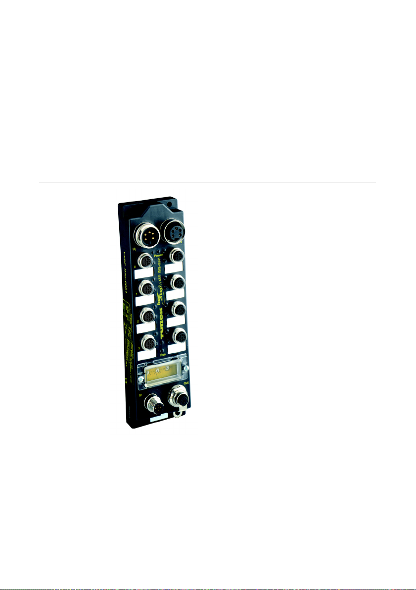
Page 50

Digital Hybrid Modules
Digital hybrid module, 2 x 8-channel, I/I or O/O per connector
FXDP-IOM88-0001
The busstop® input/output station FXDP-IOM88-0001 is a modular
PROFIBUS-DP slave in a compact housing design.
Up to eight 2/3 wire pnp sensors and eight DC actuators with a
maximum output current of 1.4 A per output can be connected.
The inputs and outputs are provided equidirectionally via four
connectors.
Figure 14:
FXDP-IOM88-0001
D300720 0905 - FXDP4-2
Page 51

Digital hybrid module, 2 x 8-channel, I/I or O/O per connector
Wiring diagrams
Figure 15:
Wiring diagrams
5 PE
5 PE
3 BU –
4 BK
1 BN +
2 WH
3 BU –
4 BK +
1
2 WH +
3 BU –
4
D300720 0905 - FXDP 4-3
Page 52

Digital Hybrid Modules
Technical data
Table 22:
Technical data
FXDP-IOM88-0001
Type FXDP-IOM88-0001
Configuration file TU4_ff1f.gsd
Inputs (8) 2/3 wire pnp sensors
Supply (via UB) 24 VDC (18 ... 30 VDC)
Supply current < 120 mA per connector,
short-circuit protected
Switching threshold
2 mA/4 mA
OFF/ON
Switching current
6 mA
limitation
Switch-on delay 2,5 ms
Switching frequency < 250 Hz
Galvanic isolation galvanic isolation to PROFIBUS-DP
Outputs (8) DC-actuators
Load supply (via UL) 24 VDC (18 ... 30 VDC)
Output current 1.4 A, short-circuit protected
(ON period = 50 %)
Switching frequency < 250 Hz
Galvanic isolation galvanic isolation to PROFIBUS-DP
Housing
EMC to EN 61000-6-2,
EN 61000-6-4;
EN 61326/1999; A1/1999
Approval for use in
Zone 2
to EN 50014/2000,
EN 50021/2000 /
É II 3 G EEx nA IIC T4 X
D300720 0905 - FXDP4-4
Page 53

Digital hybrid module, 2 x 8-channel, I/I or O/O per connector
Parameterization
Table 23:
Parameter data
assignment
Param.-
Parameter Meaning
Byte
0 to 6 Standard DP parameters according to PROFIBUS-
DP standard
7 to 9 Standard DPV1 parameters according to PROFIBUS-
DP standard
10 and 1100, 00
not parameterizable
12 and 13AA, AA
The connectors 0-3 are
defined as inputs, the
connectors 4-7 are
defined as outputs.
not parameterizable
14 and 15reserved -
16 UL diagnosis
Activation of UL diagnosis
00 = diagnosis is not transferred via the bus
01 = diagnosis is transferred via the bus
Diagnosis
diagnostic messages in the diagnosis telegram:
4
Table 24:
Diagnostic
messages
Diagnostic
message
Meaning
Short circuit Channel wise diagnosis for short circuits at
the connected sensor/ actuator.
Undervoltage Operation voltage UB missing or < 18 VDC
Load voltage
Load voltage UL missing or < 18 VDC
missing
D300720 0905 - FXDP 4-5
Page 54

Digital Hybrid Modules
diagnosis in process data image
Table 25:
process data
Input Bit 7 Bit 6 Bit 5 Bit 4 Bit 3 Bit 2 Bit 1 Bit 0
Byte 0 C3P2 C3P4 C2P2 C2P4 C1P2 C1P4 C0P2 C0P4
Output Bit 7 Bit 6 Bit 5 Bit 4 Bit 3 Bit 2 Bit 1 Bit 0
Byte 0 C7P2 C7P4 C6P2 C6P4 C5P2 C5P4 C4P2 C4P4
Diagn. A Bit 7 Bit 6 Bit 5 Bit 4 Bit 3 Bit 2 Bit 1 Bit 0
Byte 0 U
U
B
SC
L
Byte1 SC 7 SC 6 SC 5 SC 4 SC 3 SC 2 SC 1 SC 0
Byte2 SC 15 SC 14 SC 13 SC 12 SC 11 SC 10 SC 9 SC 8
Byte3 Con 7 Con 6 Con 5 Con 4 Con 3 Con 2 Con 1 Con 0
A Depending on the configuration, the manufacturer specific diagnosis
data can be mapped into the user data area
.
CxPy Status: connector x, pin y
SC Common short-circuit indication
SCx Short-circuit indication channel x
Conx Overload sensor voltage: connector x
U
B
U
L
UB < 18 VDC
UL <18 VDC
Bit is not used
D300720 0905 - FXDP4-6
Page 55

Digital combined module, 2 x 8-channel, I/O per connector
Digital combined module, 2 x 8-channel, I/O per connector
FXDP-CSG88-0001
The busstop® input/output station FXDP-CSG88-0001 is a modular
PROFIBUS-DP slave in a compact housing design.
Up to eight 2/3 wire pnp sensors and eight DC actuators with a
maximum output current of 1.4 A per output can be connected.
The inputs and outputs are provided in combination by eight
connectors.
Figure 16:
FXDP-CSG88-0001
4
D300720 0905 - FXDP 4-7
Page 56

Digital Hybrid Modules
Wiring diagram
Figure 17:
Wiring diagram
PE
3 () BU
5
4 ( ) BK
1 (+) BN
2
D300720 0905 - FXDP4-8
Page 57

Digital combined module, 2 x 8-channel, I/O per connector
Technical data
Table 26:
Technical data
FXDP-CSG88-0001
Type FXDP-CSG88-0001
Configuration file TU5_ff1f.gsd
Inputs (8) 2/3 wire pnp sensors
Supply (via UB) 24 VDC (18 ... 30 VDC)
Supply current < 120 mA per connector,
short-circuit protected
Switching threshold
2 mA/4 mA
OFF/ON
Switching current
6 mA
limitation
Switch-on delay 2,5 ms
Switching frequency < 250 Hz
Galvanic isolation galvanic isolation to PROFIBUS-DP
Outputs (8) DC-actuators
Load supply (via UL) 24 VDC (18 ... 30 VDC)
Output current 1.4 A, short-circuit protected
(ON period = 50 %)
4
Switching frequency < 250 Hz
Galvanic isolation galvanic isolation to PROFIBUS-DP
Housing
EMC to EN 61000-6-2,
EN 61000-6-4;
EN 61326/1999; A1/1999
Approval for use in
Zone 2
to EN 50014/2000,
EN 50021/2000 /
É II 3 G EEx nA IIC T4 X
D300720 0905 - FXDP 4-9
Page 58

Digital Hybrid Modules
Parameterization
Table 27:
Parameter data
assignment
Param.-
Parameter Meaning
Byte
0 to 6 Standard DP parameters according to PROFIBUS-
DP standard
7 to 9 Standard DPV1 parameters according to PROFIBUS-
DP standard
10 and 1188, 88
not parameterizable
12 and 1388, 88
Pin 2 of the connectors is
defined a output, pin 4 as
input.
not parameterizable
14 and 15reserved -
16 UL diagnosis
Activation of UL diagnosis
00 = diagnosis is not transferred via the bus
01 = diagnosis is transferred via the bus
Diagnosis
diagnostic messages in the diagnosis telegram:
Table 28:
Diagnostic
messages
Diagnostic
Meaning
message
Short circuit Channel wise diagnosis for short circuits at
the connected sensor/ actuator.
Undervoltage Operation voltage UB missing or < 18 VDC
Load voltage
Load voltage UL missing or < 18 VDC
missing
D300720 0905 - FXDP4-10
Page 59

Digital combined module, 2 x 8-channel, I/O per connector
diagnosis in process data image
Table 29:
process data
Input Bit 7 Bit 6 Bit 5 Bit 4 Bit 3 Bit 2 Bit 1 Bit 0
Byte 0 C7P4 C6P4 C5P4 C4P4 C3P4 C2P4 C1P4 C0P4
Output Bit 7 Bit 6 Bit 5 Bit 4 Bit 3 Bit 2 Bit 1 Bit 0
Byte 0 C7P2 C6P2 C5P2 C4P2 C3P2 C2P2 C1P2 C0P2
Diagn. A Bit 7 Bit 6 Bit 5 Bit 4 Bit 3 Bit 2 Bit 1 Bit 0
Byte 0 U
U
B
SC
L
Byte1 SC 7 SC 6 SC 5 SC 4 SC 3 SC 2 SC 1 SC 0
Byte2 SC 15 SC 14 SC 13 SC 12 SC 11 SC 10 SC 9 SC 8
Byte3 Con 7 Con 6 Con 5 Con 4 Con 3 Con 2 Con 1 Con 0
A Depending on the configuration, the manufacturer specific diagnosis
data can be mapped into the user data area
.
CxPy Status: connector x, pin y
SC Common short-circuit indication
SCx Short-circuit indication channel x
Conx Overload sensor voltage: connector x
U
B
U
L
UB < 18 VDC
UL <18 VDC
Bit is not used
4
D300720 0905 - FXDP 4-11
Page 60

Digital Hybrid Modules
D300720 0905 - FXDP4-12
Page 61

5 Universal Service Module
FXDP-XSG16-0001 ............................................................................ 2
The service module .....................................................................................2
Block diagram .............................................................................................4
Wiring diagrams ..........................................................................................5
Technical data.............................................................................................6
Configuration options..................................................................................7
Parameterization .........................................................................................8
Diagnosis.....................................................................................................9
– Diagnostic messages in the diagnosis telegram .....................................9
– Diagnosis in the process data image ....................................................10
D300720 0905 - FXDP 5-1
Page 62

Universal Service Module
FXDP-XSG16-0001
The busstop® input/output station FXDP-XSG16-0001 is a modular
PROFIBUS-DP slave in a compact housing design. The module is
equipped with sixteen channels, which can be configured differently
depending on the specific application requirements. Up to sixteen
2/3 wire pnp sensors or sixteen DC actuators with a maximum
output current of 1.4 A per output can be connected.
The service module
Besides the typical FXDP properties like the extended diagnosis, the
possibility of diagnosis-data mapping into the user data as well as
the FIXCON
FXDP-XSG16-0001 provides the following additional features:
Each single channel can be configured according to the applica-
tion via configuration software tools (e.g. SIMATIC Manager,
etc.). The required combination of in- and outputs can be exactly
planned to suit the customer’s needs. The device’s configuration
options enable the user to operate the module in the “AUTO
mode” or to use the individual channels as an input, as an
inverted input, as a diagnostic input or as an output. This thus
ensures a 100% technology utilization and a cost minimization.
Operating FXDP-modules can directly be replaced by the XSG-
module. Without any additional configuration, it can take-over
the function of the module that has to be replaced. The customer
only has to change the hardware, to set the previously config
ured PROFIBUS-DP address at the XSG-module and to execute
a voltage reset at the module.
Based on this fact, the module is universally applicable and can be
used to reduce inventory costs and system down-times - two
factors that are constantly gaining in importance in face of ever more
complex technical processes.
®
I/O-connection technology, the service module
-
D300720 0905 - FXDP5-2
Page 63

FXDP-XSG16-0001
Figure 18:
FXDP-XSG16-0001
5
D300720 0905 - FXDP 5-3
Page 64

Universal Service Module
Block diagram
Figure 19:
Block diagram
FXDP-XSG16-0001
Figure 20:
Setting the loop
for wire break
detection
A
2
U (24 V)
B
A
Wire-break detection via external bridge between PIN 2
and U . Only realizable with the parameterization of
13
5
B
GND
4
Input
Invert. Input
Diag. Input
Output
Input
Invert. Input
Output
as “Diag. Input”.
Pin 2 = channel 1, 3, 5,... (all impair channel numbers)
Pin 4 = channel 0, 2, 4 ...(all pair channel numbers)Figure
Example for wire break detection:
3 BU –
5 PE 4 BK
1 BN +
2WH
3 BU –
Loop for wire break detection
PIN 2
input A
(actuator)
D300720 0905 - FXDP5-4
Page 65

FXDP-XSG16-0001
Wiring diagrams
Figure 21:
Wiring diagrams
Connection of 2 actuators:
5 PE
4 BK +
1
2 WH +
3 BU –
Connection of 2 sensors:
3 BU –
5 PE
4 BK
1 BN +
2 WH
3 BU –
Combinations of sensor and actuator:
3 () BU
5
PE
5
PE
4 ( ) BK
1 (+) BN
2
3 () BU
4 (+) BK
1 (+) BN
2 ( ) WH
5
D300720 0905 - FXDP 5-5
Page 66

Universal Service Module
Technical data
Table 30:
Technical data
FXDP-XSG16-0001
Type FXDP-XSG16-0001
Configuration file TU6_ff1f.gsd
Inputs (configurable) ((n) 2/3 wire pnp sensors (n = 0...16)
Supply (via UB) 24 VDC (18 ... 30 VDC)
Supply current < 120 mA per connector, short-circuit
protected
Switching threshold
2 mA/4 mA
OFF/ON
Switching current
6 mA
limitation
Switch-on delay 2,5 ms
Switching frequency < 250 Hz
Galvanic isolation galvanic isolation to PROFIBUS-DP
Outputs (configurable) (16-n) DC actuators (n = 0...16)
Load supply (via UL) 24 VDC (18 ... 30 VDC)
Output current 1.4 A, short-circuit protected (ON
period = 35 %)
Switching frequency < 250 Hz
Galvanic isolation galvanic isolation to PROFIBUS-DP
Housing
EMC to EN 61000-6-2,
EN 61000-6-4;
EN 61326/1999; A1/1999
Approval for use in
Zone 2
to EN 50014/2000,
EN 50021/2000 /
É II 3 G EEx nA IIC T4 X
D300720 0905 - FXDP5-6
Page 67

FXDP-XSG16-0001
Configuration options
Table 31:
´Configuration
options for the
universal service
module
User data
area
FXDP-IM8-0001
FXDP-IM16-0001
FXDP-OM8-0001
FXDP-OM16-0001
FXDP-IOM88-0001
FXDP-CSG88-0001
Comment
FXDP-XSG16-0001
8 Bit IN x x I per connector
16 Bit IN x x I/I per connector
8 Bit OUT x x O per connector
16 Bit OUT x x O/O per connector
8 Bit IN,
8 Bit OUT
8 Bit IN,
x x I/I bzw. O/O per
connector
x x I/O per connector
8 Bit OUT
8 Bit IN,
8 Bit DIAG
8 Bit OUT,
8 Bit DIAG
12 Bit IN,
4 Bit OUT
n Bit IN,
16-n Bit OUT
x I/DIAG per
connector
x O/DIAG per
connector
x I/I bzw. O/O per
connector
x outputs are read
back
(AUTO Mode)
5
n Bit IN,
16-n Bit OUT
(PROG Mode)
x channel config-
urable as IN,
inverted IN,
DIAG IN or OUT
AddOn:
Diag mapped
x x x x x x x diagnostics mapped
to user data area
D300720 0905 - FXDP 5-7
Page 68

Universal Service Module
Parameterization
Table 32:
Parameter data
assignment
A The parameterization of the input as diagnostic
input can only be
realized if the in
put is connected
to Pin
2
-
Param.-
Parameter Meaning
Byte
0 to 6 Standard DP parameters according to PROFIBUS-
DP standard
7 to 9 Standard DPV1 parameters according to PROFIBUS-
DP standard
10 Channel-parameter [0]
00 = input
01 = inverted Input
10 = output
Channel-function
(Channel 0-3)
2 Bit define the function of
the respective channel.
11 = diagnostic input A
11 Channel-parameter [1]
00 = input
01 = inverted Input
10 = output
Channel-function
(Channel 4-7)
2 Bit define the function of
the respective channel.
11 = diagnostic input A
12 Channel-parameter [2]
00 = input
01 = inverted Input
10 = output
Channel-function
(Channel 8-11)
2 Bit define the function of
the respective channel.
11 = diagnostic input A
13 Channel-parameter [3]
00 = input
01 = inverted Input
10 = output
Channel-function
(Channel 12-15)
2 Bit define the function of
the respective channel.
11 = diagnostic input A
14 reserved -
15 reserved -
16 UL diagnosis
00 = diagnosis is not transferred via the bus
01 = diagnosis is transferred via the bus
Activation of UL diagnosis
D300720 0905 - FXDP5-8
Page 69

FXDP-XSG16-0001
Diagnosis
Diagnostic messages in the diagnosis telegram
Table 33:
diagnostic
messages
Diagnostic message Meaning
Short circuit Channel wise diagnosis for short circuits
at the connected sensor/ actuator.
Wire-break Indication of a wire-break in the sensor- /
or actuator line (please read the following
„Note“).
The wire-break indication is inverted:
diagnostic bit = 0 → no diagnosis
diagnostic bit = 1 → wire-break at Diag.IN
Undervoltage Operation voltage UB missing or
<
18 VDC
Load voltage missing Load voltage UL missing or < 18 VDC
Note
The Pin 2-diagnosis „wire-break“ can only be realized with the module FXDP-XSG-0001 configured as „IM8D8“, „OM8D8“ or
„XSG16: 16 IN/ 16 OUT (Prog. Mode)“ (see „Configuration options”,
Page 5-7).
Note
A wire-break can only be detected if Pin 1 (UB - supply) and Pin 2 are
bridged at the sensor or at the actuator.
5
D300720 0905 - FXDP 5-9
Page 70

Universal Service Module
Diagnosis in the process data image
Table 34:
process data
Input Bit 7 Bit 6 Bit 5 Bit 4 Bit 3 Bit 2 Bit 1 Bit 0
Byte 0 C3P2 C3P4 C2P2 C2P4 C1P2 C1P4 C0P2 C0P4
Byte 1 C7P2 C7P4 C6P2 C6P4 C5P2 C5P4 C4P2 C4P4
Output Bit 7 Bit 6 Bit 5 Bit 4 Bit 3 Bit 2 Bit 1 Bit 0
Byte 0 C3P2 C3P4 C2P2 C2P4 C1P2 C1P4 C0P2 C0P4
Byte 1 C7P2 C7P4 C6P2 C6P4 C5P2 C5P4 C4P2 C4P4
Diagn. A Bit 7 Bit 6 Bit 5 Bit 4 Bit 3 Bit 2 Bit 1 Bit 0
Byte 0 U
U
B
SC
L
Byte1 SC 7 SC 6 SC 5 SC 4 SC 3 SC 2 SC 1 SC 0
Byte2 SC 15 SC 14 SC 13 SC 12 SC 11 SC 10 SC 9 SC 8
Byte3 Con 7 Con 6 Con 5 Con 4 Con 3 Con 2 Con 1 Con 0
A Depending on the configuration, the manufacturer specific diagnosis
data can be mapped into the user data area.
CxPy Status: connector x, pin y
SC Common short-circuit indication
SCx Short-circuit indication channel x
Conx Overload sensor voltage: connector x
U
B
U
L
UB < 18 VDC
UL <18 VDC
D300720 0905 - FXDP5-10
Page 71

6 Connection to a Siemens PLC S7
General .............................................................................................. 2
Reading- in the GSD File.................................................................... 3
– Reading-in the GSD files before starting the software ............................3
– Reading-in the GSD files after starting the software ...............................3
Selecting the FXDP Modules as Slaves ............................................. 5
Configuring the FXDP modules...................................................................6
Diagnostic messages in the process image................................................7
Parameterization of the FXDP modules ............................................. 8
Diagnosis evaluation on a S7-PLC ..................................................... 9
Online diagnosis with die SIMATIC Manager..............................................9
Diagnosis via function block FB125..........................................................12
D300720 0905 - FXDP 6-1
Page 72

Connection to a Siemens PLC S7
General
The software „SIMATIC Manager“ V 5.1 with Service Pack 6 from
Siemens is used to configure the connection of FXDP modules with
the Siemens S7 PLC.
The CPU used in the S7 in the following example was a
CPU 315-2AF02-0AB0 with firmware version 3.
D300720 0905 - FXDP6-2
Page 73

Reading- in the GSD File
Reading- in the GSD File
The GSD files for FXDP must be read into the software before you
can begin with the initial configuration. There are two procedures
possible for reading-in the files:
Reading-in the GSD files before starting the software
Copy the GSD files „TUx_ff1f.gsd“ for the FXDP into the
„Step7\S7data\GSD“ directory.
Copy the icon files (*.bmp) into the „Step7\S7data“ directory.
Start the „SIMATIC Manager“ software.
The FXDP modules will automatically be entered into the hard-
ware overview following correct installation of the files. The hardware overview can be accessed using the <Insert → Hardware
Catalog> command.
Reading-in the GSD files after starting the software
Proceed as follows to read-in the above GSD files, if you have
already started the software.
Create a new or open an existing project.
Open the hardware configuration software.
Copy the required GSD file using the <Options → Install New
*.GSD...> command.
6
Figure 21:
Reading-in the
GSD files using
„Install New
*.GSD...“
D300720 0905 - FXDP 6-3
Page 74

Connection to a Siemens PLC S7
Select the GSD file from the corresponding source directory.
Figure 22:
Selection of the
GSD files from the
corresponding
source directory
The GSD files are listed as separate entries in the hardware
catalog following correct installation.
Figure 23:
FXDP modules in
the hardware
catalog
Note
The exact configuration procedure can be found in the operators
manual, which is supplied with the software.
D300720 0905 - FXDP6-4
Page 75

Selecting the FXDP Modules as Slaves
Selecting the FXDP Modules as Slaves
To insert a FXDP module as a slave, select the required entry from
the hardware catalog.
Figure 24:
Inserting a FXDP
module as a slave
6
D300720 0905 - FXDP 6-5
Page 76

Connection to a Siemens PLC S7
Configuring the FXDP modules
After the selection of a module as modular slave, the function of the
module has to be defined.
Please choose one of the module’s configuration options from the
hardware catalog.
Figure 25:
Configuration of
the slave
D300720 0905 - FXDP6-6
Page 77

Selecting the FXDP Modules as Slaves
Diagnostic messages in the process image
The FXDP modules offer the possibility to map the diagnosis data
into the process image.
This can be achieved by adding the function „Add On: Diagnosis in
I/O-Data“ to the module’s configuration.
Figure 26:
Add on: Diagnosis
in I/O-Data
6
D300720 0905 - FXDP 6-7
Page 78

Connection to a Siemens PLC S7
Parameterization of the FXDP modules
If parameterizable modules have been chosen, the slave properties
can be opened with a double click on the respective module.
Figure 27:
Parameterizing a
FXDP module
D300720 0905 - FXDP6-8
Page 79

Diagnosis evaluation on a S7-PLC
Diagnosis evaluation on a S7-PLC
In the following example, a S7 PLC with the CPU 315-2AF02-0AB0,
firmware version 3, is used for diagnosis evaluation.
Note
A correct diagnosis-data evaluation cannot be guaranteed if S7
PLCs with older hard- or firmware-version are used.
The diagnosis evaluation of the FXDP modules can be done either
via the online diagnosis in the hardware configurator of the SIMATIC
software or via the Siemens function block FB125. This function
block enables the visualization of plain text diagnosis on systems of
different manufacturers.
Online diagnosis with die SIMATIC Manager
For the online diagnosis you have to go online with the configured
FXDP station in the hardware catalog.
A pending diagnosis is shown in the software with a red symbol at
the module image . A double click on the module opens the window
„Object
properties...“.
The register „DP Slave Diagnostics...“ shows the plain text diagnostic message, the slot number which accords to the connector’s
number on the FXDP modules and the channel number.
Note
The plain text diagnosis is an evaluation of standardized error
codes, which are sent by the FXDP modules.
According to the PROFIBUS-DP standard, the meanings of the error
codes 1-11 are defined (i.e. 1 = „Short circuit“, 6 = „Wire break“).
All other error codes may differ in their interpretation, always depending on the programming software that is used.
6
D300720 0905 - FXDP 6-9
Page 80

Connection to a Siemens PLC S7
The button „Hex Format...“ opens the window „Diagnosis in Hexadecimal Format“ which shows the module’s entire diagnosis telegram.
Figure 28:
Module
information
Note
The software „SIMATIC Manager“ only interprets the standardized
error codes in the online diagnosis.
D300720 0905 - FXDP6-10
Page 81

Diagnosis evaluation on a S7-PLC
The following example shows a simulated failure in the load voltage
supply (U
). The software can not interpret the diagnostic message
L
„No encoder voltage or load voltage“ (error code 17), because it is
not standardized.
Figure 29:
Error code 17 (not
standardized)
6
D300720 0905 - FXDP 6-11
Page 82

Connection to a Siemens PLC S7
Diagnosis via function block FB125
The following description shows the diagnosis with function block
125 version V4.5. You can download the actual version of the func
tion block directly from the Siemens homepage.
Note
Please read the function block’s description from Siemens for all information about structure and handling of FB 125.
In order to use the FB125, all „software blocks“ and „symbols“ of
the function block have to be copied into the project.
Figure 30:
Project with
FB125
-
Online-access to the modules’ diagnostic messages is possible via
the variable table VAT125 or the data block DB125.
D300720 0905 - FXDP6-12
Page 83

Diagnosis evaluation on a S7-PLC
The following example shows a diagnostic message with error
6 („Wire break“) at station 22, channel 0.
code
Figure 31:
VAT125 with diagnostic message
6
The function block FB125 transmits the diagnostic messages to
higher-level operating panels which interpret the error codes and
display them as plain text diagnosis.
D300720 0905 - FXDP 6-13
Page 84

Connection to a Siemens PLC S7
D300720 0905 - FXDP6-14
Page 85

7 Appendix
Declaration of conformity .................................................................. 2
D300720 0905 - FXDP 0-1
Page 86

Appendix
Declaration of conformity
Figure 32:
Declaration of
conformity
D300720 0905 - FXDP7-2
Page 87

8 Glossary
Acknowledge
A
Acknowledgment of a signal received.
Active metal component
Conductor or conducting component that is electrically live during operation.
Address
Identification number of, e.g. a memory position, a system or a module within
a network.
Addressing
Allocation or setting of an address, e. g. for a module in a network.
Analog
Infinitely variable value, e. g. voltage. The value of an analog signal can take on
any value, within certain limits.
Automation device
A device connected to a technical process with inputs and outputs for control.
Programmable logic controllers (PLC) are a special group of automation
devices.
Baud
B
Baud is a measure for the transmission speed of data. 1 Baud corresponds to
the transmission of one bit per second (Bit/s).
Baud rate
Unit of measurement for measuring data transmission speeds in Bit/s.
Bidirectional
Working in both directions.
D300720 0905 - FXDP 8-1
Page 88

Glossary
Bus
Bus system for data exchange, e. g. between CPU, memory and I/O levels. A
bus can consist of several parallel cables for data transmission, addressing,
control and power supply.
Bus cycle time
Time required for a master to serve all slaves or stations in a bus system, i. e.
reading inputs and writing outputs.
Bus line
Smallest unit connected to a bus, consisting of a PLC, a coupling element for
modules on the bus and a module.
Bus system
All units which communicate with one another via a bus.
Capacitive coupling
C
Electrical capacitive couplings occur between cables with different potentials.
Typical sources of interference are, for example, parallel-routed signal cables,
contactors and electrostatic discharges.
Coding elements
Two-piece element for the unambiguous assignment of electronic and base
modules.
Configuration
Systematic arrangement of the I/O modules of a station.
CPU
Central Processing Unit. Central unit for electronic data processing, the
processing core of the PC.
Digital
D
A value (e. g. a voltage) which can adopt only certain statuses within a finite set,
mostly defined as 0 and 1.
DIN
German acronym for German Industrial Standard.
D300720 0905 - FXDP8-2
Page 89

EIA
E
Electronic Industries Association – association of electrical companies in the
United States.
Electrical components
All objects that produce, convert, transmit, distribute or utilize electrical power
(e. g. conductors, cable, machines, control devices).
EMC
Electromagnetic compatibility – the ability of an electrical part to operate in a
specific environment without fault and without exerting a negative influence on
its environment.
EN
German acronym for European Standard.
ESD
Electrostatic Discharge.
Field power supply
F
Voltage supply for devices in the field as well as the signal voltage.
Fieldbus
Data network on sensor/actuator level. A fieldbus connects the equipment on
the field level. Characteristics of a fieldbus are a high transmission security and
real-time behavior.
GND
G
Abbreviation of ground (potential „0“).
Ground
Expression used in electrical engineering to describe an area whose electrical
potential is equal to zero at any given point. In neutral grounding devices, the
potential is not necessarily zero, and one speaks of the ground reference.
Ground connection
One or more components that have a good and direct contact to earth.
8
D300720 0204 - FXDP 8-3
Page 90

Glossary
Ground reference
Potential of ground in a neutral grounding device. Unlike earth whose potential
is always zero, it may have a potential other than zero.
GSD
Acronym for Electronic Device Data Sheet which contains standardized
PROFIBUS DP station descriptions. They simplify the planning of the DP
master and slaves. Default language is English.
Hexadecimal
H
System of representing numbers in base 16 with the digits 0 ... 9, and further
with the letters A, B, C, D, E and F.
Hysteresis
A sensor can get caught up at a certain point, and then “waver“ at this position.
This condition results in the counter content fluctuating around a given value.
Should a reference value be within this fluctuating range, then the relevant
output would be turned on and off in rhythm with the fluctuating signal.
I/O
I
Input/output.
Impedance
Total effective resistance that a component or circuit has for an alternating
current at a specific frequency.
Inactive metal components
Conductive components that cannot be touched and are electrically isolated
from active metal components by insulation, but can adopt voltage in the event
of a fault.
Inductive coupling
Magnetic inductive couplings occur between two cables through which an
electrical current is flowing. The magnetic effect caused by the electrical
currents induces an interference voltage. Typical sources of interference are for
example, transformers, motors, parallel-routed network and HF signal cables.
D300720 0905 - FXDP8-4
Page 91

Intelligent modules
Intelligent modules are modules with an internal memory, able to transmit
certain commands (e. g. substitute values and others).
Load value
L
Predefined value for the counter module with which the count process begins.
Lightning protection
All measures taken to protect a system from damage due to overvoltages
caused by lightning strike.
Low impedance connection
Connection with a low AC impedance.
LSB
Least Significant Bit
Mass
M
All interconnected inactive components that do not take on a dangerous touch
potential in the case of a fault.
Master
Station in a bus system that controls the communication between the other
stations.
8
Master/slave mode
Mode of operation in which a station acting as a master controls the communication between other stations in a bus system.
Module bus
The module bus is the internal bus in a BL20 station. The BL20 modules
communicate with the gateway via the module bus which is independent of the
fieldbus.
MSB
Most Significant Bit
D300720 0204 - FXDP 8-5
Page 92

Glossary
Multi-master mode
Operating mode in which all stations in a system communicate with equal
rights via the bus.
NAMUR
N
German acronym for an association concerned with standardizing measurement and control engineering. NAMUR initiators are special versions of the
two-wire initiators. NAMUr initiators are characterized by their high immunity to
interference and operating reliability, due to their special construction (low
internal resistance, few components and compact design).
Overhead
O
System administration time required by the system for each transmission
cycle.
PLC
P
Programmable Logic Controller.
Potential compensation
The alignment of electrical levels of electrical components and external
conductive components by means of an electrical connection.
Potential free
Galvanic isolation of the reference potentials in I/O modules of the control and
load circuits.
Potential linked
Electrical connection of the reference potentials in I/O modules of the control
and load circuits.
PROFIBUS-DP
PROFIBUS bus system with DP protocol. DP stands for decentralized
periphery. PROFIBUS-DP is based on DIN 19245 Parts 1 + 3 and has been
integrated into the European fieldbus standard EN 50170.
It ensures a fast cyclic data exchange between the central DP master and the
decentralized periphery devices (slaves). Its universal use is realized by the
multi master concept.
D300720 0905 - FXDP8-6
Page 93

PROFIBUS-DP address
Each PROFIBUS-DP module is assigned an explicit PROFIBUS-DP address,
with which it can be queried by the master.
PROFIBUS-DP master
The PROFIBUS-DP master is the central station on the bus and controls
access of all stations to PROFIBUS.
PROFIBUS-DP slave
PROFIBUS-DP slaves are queried by the PROFIBUS-DP master and exchange
data with the master on request.
Protective earth
Electrical conductor for protection against dangerous shock currents. Generally represented by PE (protective earth).
Radiation coupling
R
A radiation coupling appears when an electromagnetic wave hits a conductive
structure. Voltages and currents are induced by the collision. Typical sources
of interference are for example, sparking gaps (spark plugs, commutators from
electric motors) and transmitters (e. g. radio), that are operated near to
conducting structures.
Reaction time
The time required in a bus system between a reading operation being sent and
the receipt of an answer. It is the time required by an input module to change
a signal at its input until the signal is sent to the bus system.
8
Reference potential
Potential from which all voltages of connected circuits are viewed and/or
measured.
Repeater
The phase and the amplitude of the electric data signals are regenerated during
the transmission process by the repeater.
Further, it is possible to change the topology of the PROFIBUS network. It can
be extended considerably by means of the repeater.
D300720 0204 - FXDP 8-7
Page 94

Glossary
Root-connecting
Creating a new potential group using a power distribution module. This allows
sensors and loads to be supplied individually.
RS 485
Serial interface in accordance with EIA standards, for fast data transmission via
multiple transmitters.
Serial
S
Type of information transmission, by which data is transmitted bit by bit via a
cable.
Setting parameters
Setting parameters of individual stations on the bus and their modules in the
configuration software of the master.
Shield
Conductive screen of cables, enclosures and cabinets.
Shielding
Description of all measures and devices used to join installation components
to the shield.
Short-circuit proof
Characteristic of electrical components. A short-circuit proof part withstands
thermal and dynamic loads which can occur at its place of installation due to a
short circuit.
Station
A functional unit or I/O components consisting of a number of elements.
SUB-D connector
9-pin connector for connecting the fieldbus to the I/O-stations.
Terminating resistance
T
Resistor on both ends of a bus cable used to prevent interfering signal reflections and which provides bus cable matching. Terminating resistors must
always be the last component at the end of a bus segment.
D300720 0905 - FXDP8-8
Page 95

To ground
Connection of a conductive component with the grounding connection via a
grounding installation.
Topology
Geometrical structure of a network or the circuitry arrangement.
UART
U
Universal Asynchronous Receiver/Transmitter. UART is a logic circuit which is
used to convert an asynchronous serial data sequence to a parallel bit
sequence or vice versa.
Unidirectional
Working in one direction.
8
D300720 0204 - FXDP 8-9
Page 96

Glossary
D300720 0905 - FXDP8-10
Page 97

9 Index
A
addressing ..................................... 1-6
B
bus termination .............................. 1-6
C
configuration files .......................... 1-7
D
Declaration of conformity .............. 7-2
diagnosis ..................................... 1-13
diagnosis evaluation ...................... 6-9
diagnostic message ...................... 6-7
dimension drawings .................... 1-12
documentation concept ................ 0-2
F
FB125 .......................................... 6-12
function block .............................. 6-12
FXDP-CSG88-0001 ....................... 4-7
FXDP-IM16-0001 ........................... 2-6
FXDP-IM8-0001 ............................. 2-2
FXDP-IOM88-0001 ........................ 4-2
FXDP-OM16-0001 ......................... 3-6
FXDP-OM8-0001 ........................... 3-2
FXDP-XSG16-0001 ....................... 5-2
O
online diagnosis ............................. 6-9
operating files ................................1-8
output modules, digital .................. 3-1
P
parameterization ............................ 6-8
plain-text diagnosis .....................1-13
prescribed Use ..............................0-3
process image ...............................6-7
product family ................................1-3
product overview ........................... 1-4
PROFIBUS-DP ........................1-6, 1-8
S
service module .......................1-5, 5-1
T
technical data, general ................1-10
transmission rates .........................1-6
U
use, prescribed ..............................0-3
G
GSD files .................................1-7, 6-3
H
hybrid modules, digital .................. 4-1
I
input modules, digital .................... 2-1
L
LED indications ........................... 1-12
load voltage ................................... 1-8
D300720 0905 - FXDP 9-1
Page 98

TURCK WORLD-WIDE HEADQUARTERS
GERMANY
Hans Turck GmbH & Co. KG
Witzlebenstraße 7
D-45472 Mülheim an der Ruhr
P. O. Box 45466 Mülheim an der Ruhr
Phone (+49) (208) 4952-0
Fax (+49) (208) 4952-2 64
E-Mail turckmh@turck.com
www.turck.com
D300720 0905
*D300782ßß0704*
Subject to change without notice
 Loading...