

Page 1
FMX-IM-2UPLI63X
Flow Monitoring – For the Connection of Intrinsically Safe
Flow Sensors
HART Device with Current and Transistor Outputs
Features
For Ex ia resp. Ex ib sensors
■
Analog output for flow
■
Transistor outputs for temperature and
■
faults
Teaching upper and lower flow limit
■
LED band for indication of flow speed and
■
media temperature
Monitoring of operating and display range
■
Detection of wire-break and short-circuit on
■
the sensor side
Parametrized via pushbutton and FDT/DTM
■
Associated equipment [Ex ia Ga / Da]
■
Connection of flow probes Zone 0 / 20
■
Technical data
Type FMX-IM-2UPLI63X
ID no. 7525105
Electrical data
Operating voltage 20…30VDC
Power consumption <10.5W
No-load current I
Teach modes Min/max adjustment. Teach modes incl.
Flow speed [%] after min/max adjustment (perma-
Medium temperature [°C] with the SET button temporarily
Repeatability flow rate typical ±1% (of full scale)
Repeatability media temperature typical ±1K
Measuring accuracy media temperature typical ±7K
Switchpoint hysteresis media temperature
Input function Connection of flow sensors
Sensor voltage ≤7VDC
Sensor current ≤70mA
Sensor current limitation approx.110mA
Measuring frequency 5 Hz (every 200 ms with software filter)
0
Output functions
Flow monitoring Analog output
≤63mA
DeltaFlow monitoring (teach modes are
automatically released with the change of
flow speed).
nent)
pressed
2K
Functional principle
All Ex FCS flow (immersion) and FCI (inline)
sensors can be operated with the external
processing unit FMX-IM.
The flow module features four status LEDs
as well as a 10-segment LED band for local
monitoring. Software-based diagnostic options
are also available to the user, such as wirebreak and short-circuit on the sensor side.
Furthermore, monitoring of flow rates and
media temperatures within a predefined
operating and display range.
The upper and lower limit are determined
in relation to the analog output signal and
implemented in the Teach mode. Working
on the calorimetric principle, the connectible
sensors not only detect the flow rate but also
the media temperature.
Parametrization is implemented either via
pushbutton or software-supported via HART
interface and then via the device specific
IODD within the FDT frame PACTware or via
SPDU.
FMX-IM-2UPLI63X | 04-05-2021 11-34 | Technical modifications reserved
Hans Turck GmbH & Co. KG | 45466 Mülheim an der Ruhr, Germany | T +49 208 4952-0 | F +49 208 4952-264 | more@turck.com | www.turck.com 1|4
Page 2

Technical data
Temperature monitoring transistor output
Error monitoring transistor output
Current range 4…20 mA / 20…4 mA parametrizable
Load <600Ω
Characteristic Output of probe signal, no linearization
Error recognition NAMUR error limits
Switching characteristic PNP
Switching state active high / active low parametrizable
(transistor output error monitoring only
active low)
Switching voltage 20…30VDC
Switching current 100mA
Electrical connections 5-pole removable reverse polarity protect-
ed terminal blocks
Connection mode screw connection
Terminal cross-section 1.5…2.5mm²
Communication modes Tool based engineering via DTM
Tests/approvals
Device marking Ex II (1) G [Ex ia Ga] IIC resp. II (1) D [Ex
EX type-examination certificate TÜV 11 ATEX 078981
IECEx certificate of conformity IECEx TUN 11.0005
Declaration of conformity EN ISO/IEC 5108M
Approvals CE, C-UL U.S. submitted
Electromagnetic compatibility (EMC) acc. to NE21
Relative humidity EN 60068-2-38
Mechanical data
Design Signal processor
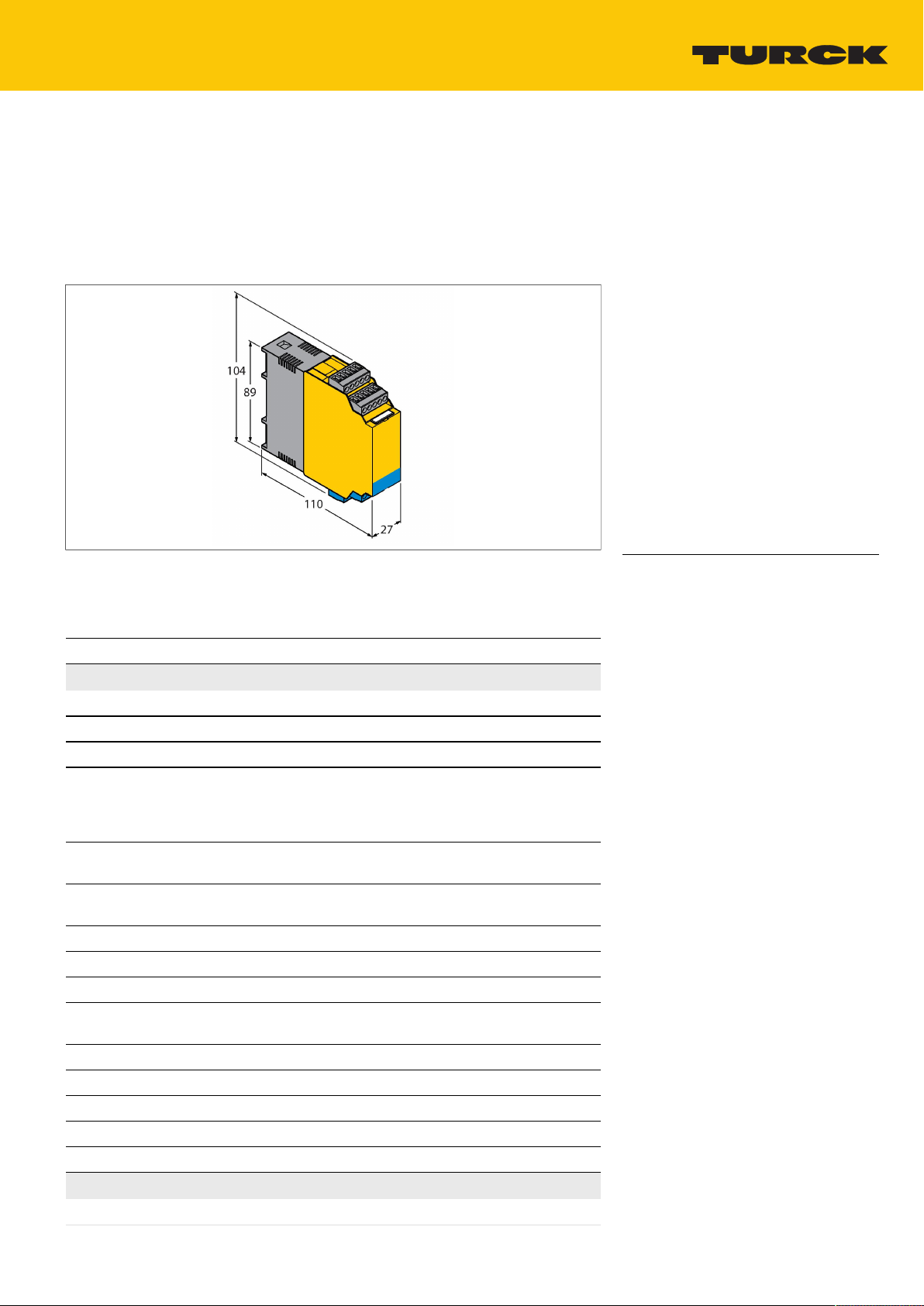
Dimensions 89x110x27mm
Housing material Polycarbonate/ABS
Ambient temperature (min.) -25
Ambient temperature (max.) 70
Mounting type DIN rail mounting and mounting panel
Protection class IP20
MTBF 108Years
ia Da] IIIC
Hans Turck GmbH & Co. KG | 45466 Mülheim an der Ruhr, Germany | T +49 208 4952-0 | F +49 208 4952-264 | more@turck.com | www.turck.com 2|4
FMX-IM-2UPLI63X | 04-05-2021 11-34 | Technical modifications reserved
Page 3
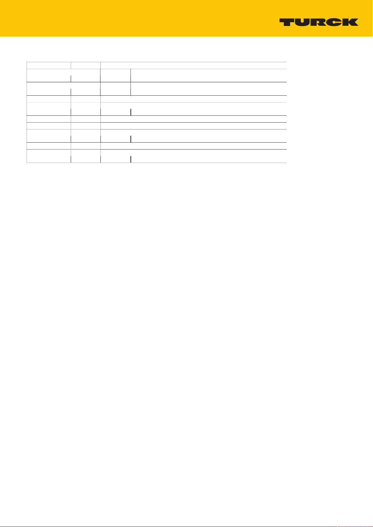
LED display
LED Color Status Description
Pwr green on Operating voltage applied
Device ready for operation
flashing Operating voltage applied
HART communication active
Flow yellow on Active current output
flashing Teach mode / display of diagnostic data
for specification see manual
Temp yellow off Switching output media temperature [low]
on Switching output media temperature [high]
flashing Teach mode / display of diagnostic data
for specification see manual
Fault Red Off Switching output fault [high]
On Switching output flow [low]
(for error pattern in combination with LEDs see manual)
For detailed description of the display patterns and flashing codes see instruction manual FMIM/FMX-IM
Hans Turck GmbH & Co. KG | 45466 Mülheim an der Ruhr, Germany | T +49 208 4952-0 | F +49 208 4952-264 | more@turck.com | www.turck.com 3|4
FMX-IM-2UPLI63X | 04-05-2021 11-34 | Technical modifications reserved
Page 4

Operating Instructions
Intended use
This device fulfills the directive 2014/34/EC and can be applied in explosion hazardous areas according to EN60079-0,
EN60079-11 and EN61241-11 as associated equipment for connection to intrinsically safe flow sensors.In order to ensure correct operation to the intended purpose it is required to observe the national regulations and directives.
For use in explosion hazardous areas conform to classification
II (1) G and II (1) D (Group II, Category (1) G, electrical equipment for gas-atmospheres and category (1) D, electrical equipment for dust atmospheres)
Marking (see device or technical data sheet)
É II (1) G [Ex ia Ga] IIC T4 acc. to EN60079-11 and EN60079-0/61241-11 and É II (1) D [Ex ia Da] IIIC
É II 1 G and EEx ia IIC T4 acc.to EN50020 and EN50284 and É II 1 D IP67 T 115°C acc.to EN50281-1-1
Local admissible ambient temperature
-25…+70 °C
Installation/Commissioning
These devices may only be installed, connected and operated by trained and qualified staff. Qualified staff must have knowledge of protection classes, directives and regulations concerning electrical equipment designed for use in explosion hazardous
areas.Please verify that the classification and the marking on the device comply with the actual application conditions.
This device is accessory equipment which features intrinsically safe circuits as well as non-intrinsically safe circuits. It may only
be installed outside the explosion hazardous area in dry, clean and well monitored areas. If a declaration of conformity or declaration of the manufacturer as a category 3 device exists, the device may be installed in zone 2. Special conditions for safe
operation must be observed. Intrinsically-safe electrical equipment can be connected to the intrinsically-safe connections. All
equipment must comply with the demands for operation in the existing zone of the explosion hazardous area. If the intrinsically safe circuits lead to the dust explosion hazardous zones 20 or 21, it is important to ensure that the devices connected to
this circuit fulfil the demands for category 1D or 2D and are certified accordingly. If the equipment is interconnected, it is necessary to perform the "Proof of intrinsic safety" (EN 60079-14). Equipment which has been used once to connect intrinsically safe circuits to non-intrinsically safe circuits is no longer suitable for subsequent use with intrinsically safe circuits. Relevant
regulations exist for the establishment of intrinsically-safe circuits, mounting of external connection parts as well as the characteristics and laying of cables. Cables and terminals with intrinsically-safe circuits must be marked. They should be separated from non-intrinsically safe circuits or must feature appropriate insulation (EN 60079-14). Observe the prescribed clearances to earthed components and connections of other devices to the intrinsically-safe connections of this device. Unless expressed specifically in the device-specific operating instructions, the approval becomes void if the device is opened, repaired
or actions are performed on the device by someone other than approved experts or the manufacturer. Visible changes to the
device housing, such as brown-black discolourations caused by heat, as well as holes or bulges also indicate a serious danger. Switch off the device immediately. With the associated electrical equipment the interconnected intrinsically-safe equipment
must also be checked. Inspection of a device with regard to the explosion protection can only be performed by an expert or the
manufacturer. The operation of the devices is only permitted in conjunction with the permitted data printed on the side of the
housing. Before any commissioning or modification of the device interconnections, ensure that the respective regulations, directives and conditions have been complied with and also ensure that use is only for the intended purpose and the safety requirements have been fulfilled.After connection to other circuits the sensor may no longer be used in Exi installations. When interconnected to (associated) electrical equipment, it is required to perform the "Proof of intrinsic safety" (EN60079-14).
Installation and mounting instructions
Avoid static charging of cables and plastic devices. Please only clean the device with a damp cloth. Do not install the device in
a dust flow and avoid build-up of dust deposits on the device.If the devices and the cable could be subject to mechanical damage, they must be protected accordingly. They must also be shielded against strong electro-magnetic fields.The pin configuration and the electrical specifications can be taken from the device marking or the technical data sheet.In order to avoid contamination of the device, please remove possible blanking plugs of the cable glands or connectors only shortly before inserting the
cable or opening the cable socket.
Special conditions for safe operation
The device must be protected against any kind of mechanical damage.
Service/Maintenance
Repairs are not possible. The approval expires if the device is repaired or modified by a person other than the manufacturer.
The most important data from the approval are listed.
Hans Turck GmbH & Co. KG | 45466 Mülheim an der Ruhr, Germany | T +49 208 4952-0 | F +49 208 4952-264 | more@turck.com | www.turck.com 4|4
FMX-IM-2UPLI63X | 04-05-2021 11-34 | Technical modifications reserved
 Loading...