

Page 1

USER MANUAL
FGEN-AIM
st
AtIoNs
wIth MultIprotocol
FUNTIONALITY
Sense it! Connect it! Bus it! Solve it!
Page 2

All brand and produ
concerned.
ct names are trademarks or registered trade marks of the owner
Edition 10/2013
© Hans Turck GmbH, Muelheim an der Ruhr
All rights reserved, including those of
No part of this manual may be reproduced i
other process) or processed, duplicated or distributed by means of electronic systems without
written permission of Hans Turck GmbH & Co. KG, Muelheim an der Ruhr.
S
ubject to alterations without notice
the translation.
n any form (printed, photocopy, microfilm or any
Page 3

Table of contents
1About this manual
1.1 Documentation concept .................................................................................................................................1-2
1.2 Description of symbols used ..........................................................................................................................1-3
1.3 General .............................................................................................................................................................1-4
1.3.1 Prescribed use ......................................................................................................................................................................................... 1-4
1.3.2 Notes concerning planning/installation of this product ......................................................................................................... 1-4
1.4 List of revisions ................................................................................................................................................1-5
2 Multi-protocol functionality
2.1 General .............................................................................................................................................................2-2
2.1.1 Protocol dependent functions .......................................................................................................................................................... 2-2
3 FGEN – general technical properties
3.1 General .............................................................................................................................................................3-2
3.2 General information on FGEN ........................................................................................................................3-3
3.3 General technical data ....................................................................................................................................3-4
3.3.1 Technical data..........................................................................................................................................................................................3-4
3.3.2 Dimension drawings ............................................................................................................................................................................. 3-5
3.3.3 LED-displays .............................................................................................................................................................................................3-5
3.4 Connection possibilities..................................................................................................................................3-6
3.4.1 Ethernet .....................................................................................................................................................................................................3-6
3.4.2 Operating/load voltage .......................................................................................................................................................................3-6
3.4.3 Analog inputs and outputs ................................................................................................................................................................. 3-7
3.5 Address assignment ........................................................................................................................................3-8
3.5.1 Default setting of the gateway..........................................................................................................................................................3-8
3.5.2 Resetting the IP-address, switch position "000".......................................................................................................................... 3-8
3.5.3 Address setting via the rotary-mode .............................................................................................................................................. 3-9
3.5.4 Address setting via the mode BootP............................................................................................................................................... 3-9
3.5.5 Address setting via the mode DHCP ............................................................................................................................................ 3-10
3.5.6 Address setting via mode PGM ...................................................................................................................................................... 3-10
3.5.7 Addressing via mode PGM-DHCP ................................................................................................................................................. 3-11
3.5.8 F_Reset (Factory Reset) ..................................................................................................................................................................... 3-11
3.5.9 Addressing via I/O-ASSISTANT 3 (FDT/DTM) ............................................................................................................................. 3-12
3.5.10 Addressing via PGM-DHCP .............................................................................................................................................................. 3-15
3.6 SET-button .................................................................................................................................................... 3-15
3.7 Device configuration files ............................................................................................................................ 3-15
3.8 Web server - remote access/configuration................................................................................................. 3-16
3.8.1 IP address ............................................................................................................................................................................................... 3-16
3.8.2 Access rights ......................................................................................................................................................................................... 3-17
3.8.3 Login / password ................................................................................................................................................................................. 3-17
3.8.4 Network Configuration ..................................................................................................................................................................... 3-18
3.8.5 Station Configuration ........................................................................................................................................................................ 3-19
3.8.6 Station Diagnostics............................................................................................................................................................................. 3-19
D301271 1013 - FGEN - multi protocol
i
Page 4

3.8.7 Ethernet Statistics ................................................................................................................................................................................3-19
3.8.8 Links.......................................................................................................................................................................................................... 3-19
3.8.9 Change Admin Password..................................................................................................................................................................3-20
3.8.10 Parameters .............................................................................................................................................................................................3-21
3.9 Status and Control Word of the FGEN-stations .......................................................................................... 3-22
3.9.1 Status Word............................................................................................................................................................................................ 3-22
3.9.2 Control Word .........................................................................................................................................................................................3-22
4 Digital inputs FGEN-IM16-x001
4.1 FGEN-IM16-x001 ............................................................................................................................................. 4-2
4.1.1 Technical data ......................................................................................................................................................................................... 4-2
4.1.2 Wiring diagrams ..................................................................................................................................................................................... 4-2
4.1.3 Parameters ............................................................................................................................................................................................... 4-3
4.1.4 Diagnostic message of I/O-channels .............................................................................................................................................. 4-3
5 Digital outputs FGEN-OM16-x001
5.1 FGEN-OM16-x001 ........................................................................................................................................... 5-2
5.1.1 Technical data ......................................................................................................................................................................................... 5-2
5.1.2 Wiring diagrams ..................................................................................................................................................................................... 5-2
5.1.3 Parameters ............................................................................................................................................................................................... 5-3
5.1.4 Diagnostic messages ............................................................................................................................................................................ 5-3
6 Digital in-/outputs FGEN-IOM88-x001, FGEN-XSG16-x001
6.1 FGEN-IOM88-x001 .......................................................................................................................................... 6-2
6.1.1 Technical data ......................................................................................................................................................................................... 6-2
6.1.2 Wiring diagrams ..................................................................................................................................................................................... 6-3
6.1.3 Parameters ............................................................................................................................................................................................... 6-3
6.1.4 Diagnostic messages ............................................................................................................................................................................ 6-4
6.2 FGEN-XSG16-000x .......................................................................................................................................... 6-5
6.2.1 Technical data ......................................................................................................................................................................................... 6-5
6.2.2 Wiring diagrams ..................................................................................................................................................................................... 6-6
6.2.3 Parameters ............................................................................................................................................................................................... 6-7
6.2.4 Diagnostic messages ............................................................................................................................................................................ 6-8
7 Implementation of EtherNet/IP™
7.1 EtherNet/IP Communications Profile ............................................................................................................ 7-2
7.1.1 I/O Messages ........................................................................................................................................................................................... 7-2
7.1.2 Explicit Messages ................................................................................................................................................................................... 7-2
7.1.3 Communications profile of FGEN .................................................................................................................................................... 7-2
7.2 QC - QuickConnect .......................................................................................................................................... 7-4
7.2.1 General ...................................................................................................................................................................................................... 7-4
7.2.2 QuickConnect in FGEN......................................................................................................................................................................... 7-4
7.3 Classes and Instances of the EtherNet/IP™-stations .................................................................................... 7-6
7.3.1 EtherNet/IP™ Standard Classes ......................................................................................................................................................... 7-6
7.3.2 Identity Object (0×01) .......................................................................................................................................................................... 7-7
7.3.3 Assembly Object (0×04) ...................................................................................................................................................................... 7-9
7.3.4 Connection Manager Object (0×06) .............................................................................................................................................7-21
7.3.5 TCP/IP Interface Object (0×F5) ........................................................................................................................................................7-22
D301271 1013 - FGEN - multi protocolii
Page 5

7.3.6 Ethernet Link Object (0×F6)............................................................................................................................................................. 7-26
7.4 VSC-Vendor Specific Classes........................................................................................................................ 7-28
7.4.1 Class instance of the VSC .................................................................................................................................................................. 7-28
7.4.2 Gateway Class (VSC 100)................................................................................................................................................................... 7-29
7.4.3 Process Data Class (VSC102)............................................................................................................................................................ 7-31
7.4.4 Digital Versatile Module Class (VSC117) ..................................................................................................................................... 7-34
7.4.5 Miscellaneous Parameters Class (VSC 126) ................................................................................................................................ 7-35
7.5 Diagnostic messages via process data........................................................................................................ 7-36
7.5.1 Summarized Diagnostics .................................................................................................................................................................. 7-36
7.5.2 Scheduled Diagnostics (manufacturer specific diagnosis) .................................................................................................. 7-36
8 Application example: FGEN for EtherNet/IP™ with Allen Bradley PLC and RS Logix 5000
8.1 General .............................................................................................................................................................8-2
8.1.1 Used hard-/ software............................................................................................................................................................................. 8-2
8.2 Network configuration....................................................................................................................................8-3
8.2.1 Configuration of the network in "RS Logix 5000" .......................................................................................................................8-3
8.2.2 Downloading the I/O configuration................................................................................................................................................8-8
8.3 I/O data mapping.......................................................................................................................................... 8-10
8.4 Process data access ...................................................................................................................................... 8-11
8.4.1 Setting outputs .................................................................................................................................................................................... 8-11
8.4.2 Example program................................................................................................................................................................................ 8-11
8.5 Activating QuickConnect ............................................................................................................................ 8-13
9 Implementation of Modbus TCP
9.1 Common Modbus description ........................................................................................................................9-2
9.1.1 Protocol description ..............................................................................................................................................................................9-3
9.1.2 Data model ...............................................................................................................................................................................................9-4
9.2 Implemented Modbus functions....................................................................................................................9-6
9.3 Modbus registers.............................................................................................................................................9-7
9.3.1 Data width of the I/O-modules in the modbus-register area.............................................................................................. 9-10
9.3.2 Register mapping of the FGEN-stations......................................................................................................................................9-11
9.3.3 Register 100Ch: "Station status"..................................................................................................................................................... 9-16
9.3.4 Register 1130h: „Modbus-Connection-Mode“.......................................................................................................................... 9-17
9.3.5 Register 1131h: „Modbus-Connection-Timeout“ .................................................................................................................... 9-17
9.3.6 Register 0×113C und 0×113D: „Restore Modbus-Connection-Parameters” ................................................................. 9-17
9.3.7 Register 0×113E und 0×113F: „Save Modbus-Connection-Parameters“ ........................................................................ 9-18
9.4 Bit areas: mapping of input-discrete- and coil-areas ................................................................................ 9-19
9.5 Error behavior of outputs (watchdog)........................................................................................................ 9-20
9.6 Parameters and diagnostic messages of the I/O channels ....................................................................... 9-21
10 Application example FGEN for Modbus TCP with CODESYS Win V3
10.1 Used hard-/ software.................................................................................................................................... 10-2
10.1.1 Hardware ................................................................................................................................................................................................ 10-2
10.1.2 Software.................................................................................................................................................................................................. 10-2
D301271 1013 - FGEN - multi protocol
iii
Page 6

10.2 Network configuration ................................................................................................................................. 10-3
10.3 Programming with CODESYS....................................................................................................................... 10-4
10.3.1 Predefined feature sets...................................................................................................................................................................... 10-4
10.3.2 Creating a new project ...................................................................................................................................................................... 10-5
10.3.3 Defining the communication settings ......................................................................................................................................... 10-7
10.3.4 Adding the Ethernet Adapter..........................................................................................................................................................10-9
10.3.5 Adding the Modbus master .......................................................................................................................................................... 10-10
10.3.6 Adding a Modbus TCP slave ......................................................................................................................................................... 10-11
10.3.7 Programming (example program) ............................................................................................................................................. 10-13
10.3.8 CODESYS: Global variables ............................................................................................................................................................ 10-14
10.3.9 Modbus channels.............................................................................................................................................................................. 10-15
10.3.10 Building, login and start ................................................................................................................................................................. 10-23
10.3.11 Reading out the process data ...................................................................................................................................................... 10-25
10.3.12 Evaluation of the status word of FGEN-XSG16-5001 (%IW1) ............................................................................................ 10-26
11 Implementation of PROFINET
11.1 FSU - Fast Start-Up (prioritized startup)..................................................................................................... 11-2
11.1.1 General ....................................................................................................................................................................................................11-2
11.1.2 FSU in FGEN ...........................................................................................................................................................................................11-2
11.2 GSDML-file..................................................................................................................................................... 11-3
11.3 PROFINET-Error Codes.................................................................................................................................. 11-4
11.4 Parameters .................................................................................................................................................... 11-5
11.4.1 General module parameters - parameters for slot 0 (turck-fgen) ...................................................................................... 11-5
11.4.2 Parameters for I/O channels ...........................................................................................................................................................11-5
11.5 Description of user data for acyclic services............................................................................................... 11-7
11.5.1 Description of the acyclic gateway user data............................................................................................................................ 11-7
11.5.2 Description of the acyclic I/O-channel user data ..................................................................................................................... 11-8
12 Application example: FGEN for PROFINET with a Siemens S7
12.1 Application example .................................................................................................................................... 12-2
12.1.1 General ....................................................................................................................................................................................................12-2
12.1.2 Example network ................................................................................................................................................................................. 12-2
12.1.3 New project in the Simatic Manager ............................................................................................................................................12-3
12.1.4 Setting the PG/PC-interface ............................................................................................................................................................. 12-3
12.1.5 Installation of the GSDML-files........................................................................................................................................................12-4
12.1.6 Adding PROFINET network nodes .................................................................................................................................................12-7
12.1.7 Scanning the network for PROFINET nodes............................................................................................................................ 12-10
12.1.8 Name assignment for FGEN-stations......................................................................................................................................... 12-11
12.1.9 PROFINET-neighborhood detection (LLDP)............................................................................................................................ 12-12
12.1.10 Online topology detection ............................................................................................................................................................ 12-15
12.1.11 Fast Start-Up - configuration of fieldbus nodes .................................................................................................................... 12-16
12.1.12 Diagnostics with Step 7 .................................................................................................................................................................. 12-18
13 Guidelines for Electrical Installation
13.1 General notes ................................................................................................................................................ 13-2
13.1.1 General ....................................................................................................................................................................................................13-2
13.1.2 Cable routing.........................................................................................................................................................................................13-2
13.1.3 Lightning protection ..........................................................................................................................................................................13-3
D301271 1013 - FGEN - multi protocoliv
Page 7

13.1.4 Transmission media............................................................................................................................................................................ 13-3
13.2 Potential relationships................................................................................................................................. 13-4
13.3 Electromagnetic compatibility(EMC ........................................................................................................... 13-5
13.3.1 Ensuring electromagnetic compatibility .................................................................................................................................... 13-5
13.3.2 Grounding of inactive metal components................................................................................................................................. 13-5
13.3.3 PE connection....................................................................................................................................................................................... 13-5
13.4 Shielding of cables ....................................................................................................................................... 13-6
13.5 Potential compensation............................................................................................................................... 13-7
13.5.1 Switching inductive loads ................................................................................................................................................................ 13-7
13.5.2 Protection against Electrostatic Discharge (ESD) .................................................................................................................... 13-7
14 Appendix
14.1 Changing the IP address of a PC/ network interface card ......................................................................... 14-2
14.1.1 Changing the IP address in Windows .......................................................................................................................................... 14-2
14.1.2 Changing the IP address via I/O-ASSISTANT V3 ....................................................................................................................... 14-4
14.2 Deactivating/ adapting the firewall in Windows ....................................................................................... 14-5
14.2.1 Addressing via DHCP ......................................................................................................................................................................... 14-7
15 Glossary
16 Index
D301271 1013 - FGEN - multi protocol
v
Page 8

D301271 1013 - FGEN - multi protocolvi
Page 9

1 About this manual
1.1 Documentation concept ............................................................................................................................ 1-2
1.2 Description of symbols used ..................................................................................................................... 1-3
1.3 General........................................................................................................................................................ 1-4
1.3.1 Prescribed use ...................................................................................................................................................................................1-4
1.3.2 Notes concerning planning/installation of this product ...................................................................................................1-4
1.4 List of revisions........................................................................................................................................... 1-5
D301271 1013 - FGEN - multi protocol 1-1
Page 10

About this manual
1.1 Documentation concept
This manual contains all information about the TURCK FGEN-product line in protection class IP67 with
multi-protocol function.
The following chapters contain:
the general technical data and station properties,
a description of the function and the assembly of the single devices in the product line,
a description of the stations' representation in the different Ethernet-protocols,
a description of the devices' handling in the different PLC-applications,
D301271 1013 - FGEN - multi protocol1-2
Page 11

Description of symbols used
1.2 Description of symbols used
Warning
This sign can be found next to all notes that indicate a source of hazards. This can refer to
danger to personnel or damage to the system (hardware and software) and to the facility.
This sign means for the operator: work with extreme caution.
Attention
This sign can be found next to all notes that indicate a potential hazard.
This can refer to possible danger to personnel and damages to the system (hardware and
software) and to the facility.
Note
This sign can be found next to all general notes that supply important information about one
or more operating steps.
These specific notes are intended to make operation easier and avoid unnecessary work due
to incorrect operation.
D301271 1013 - FGEN - multi protocol
1-3
Page 12

About this manual
1.3 General
This manual includes all information necessary for the prescribed use of the FGEN-stations. It has been
specially conceived for personnel with the necessary qualifications.
1.3.1 Prescribed use
Attention
Please read this section carefully. Safety aspects cannot be left to chance when dealing with
electrical equipment.
Warning
The devices described in this manual must be used only in applications prescribed in this
manual or in the respective technical descriptions, and only with certified components and
devices from third party manufacturers.
Appropriate transport, storage, deployment and mounting as well as careful operating and thorough
maintenance guarantee the trouble-free and safe operation of these devices.
1.3.2 Notes concerning planning/installation of this product
Warning
All respective safety measures and accident protection guidelines must be considered
carefully and without exception.
D301271 1013 - FGEN - multi protocol1-4
Page 13

List of revisions
1.4 List of revisions
In comparison to the previous manual edition, the following changes/ revisions have been made:
Table 1-1:
List of revisions
Chapter Subject new changed
3 Web server - remote access/configuration (page 3-16) x
5 Changes in th technical data of module, page 5-2 x
6 Changes in th technical data of module, page 6-2 and page
x
6-5
7 EtherNet/IP Communications Profile (page 7-2) x
Note
The publication of this manual renders all previous editions invalid.
D301271 1013 - FGEN - multi protocol
1-5
Page 14

About this manual
D301271 1013 - FGEN - multi protocol1-6
Page 15

2 Multi-protocol functionality
2.1 General........................................................................................................................................... 2-2
2.1.1 Protocol dependent functions ....................................................................................................................................................2-2
– PROFINET ........................................................................................................................................................................................ 2-2
– EtherNet/IP™ ..................................................................................................................................................................................2-2
D301271 1013 - FGEN - multi protocol 2-1
Page 16

Multi-protocol functionality
2.1 General
The compact I/O-stations of the product line FGEN combine the three Ethernet protocols EtherNet/IP™,
Modbus TCP and PROFINET in one device.
A multi-protocol device can be operated without intervention of the user (which means, without
changes in the parameterization) in all of the three Ethernet protocols mentioned.
During the start-up after a power-on, the module runs in "snooping" mode and detects the Ethernet
protocol which requests a link connection by listening the traffic.
If a protocol is detected, the device automatically changes to the detected protocol and ignores the
telegrams of the other two.
2.1.1 Protocol dependent functions
PROFINET
Fast Start-UP (FSU)
Topology discovery
Address assignment via LLDP
EtherNet/IP™
QuickConnect (QC), see page 8-13
DLR (Device Level Ring)
D301271 1013 - FGEN - multi protocol2-2
Page 17

3 FGEN – general technical properties
3.1 General........................................................................................................................................................ 3-2
3.2 General information on FGEN ................................................................................................................... 3-3
3.3 General technical data ............................................................................................................................... 3-4
3.3.1 Technical data ...................................................................................................................................................................................3-4
3.3.2 Dimension drawings ....................................................................................................................................................................... 3-5
3.3.3 LED-displays .......................................................................................................................................................................................3-5
3.4 Connection possibilities ............................................................................................................................ 3-6
3.4.1 Ethernet ...............................................................................................................................................................................................3-6
– Ethernet-connection in QC-/FSU-applications.................................................................................................................. 3-6
3.4.2 Operating/load voltage ................................................................................................................................................................. 3-6
– Voltage supply via 7/8’’, 5-pole (FGEN-xxxxx-5xx1).........................................................................................................3-7
– Voltage supply via 7/8’’, 4-pole (FGEN-xxxxx-4xx1).........................................................................................................3-7
3.4.3 Analog inputs and outputs...........................................................................................................................................................3-7
3.5 Address assignment................................................................................................................................... 3-8
3.5.1 Default setting of the gateway....................................................................................................................................................3-8
3.5.2 Resetting the IP-address, switch position "000"....................................................................................................................3-8
3.5.3 Address setting via the rotary-mode ........................................................................................................................................3-9
3.5.4 Address setting via the mode BootP.........................................................................................................................................3-9
3.5.5 Address setting via the mode DHCP ...................................................................................................................................... 3-10
3.5.6 Address setting via mode PGM ................................................................................................................................................ 3-10
3.5.7 Addressing via mode PGM-DHCP ........................................................................................................................................... 3-11
– PROFINET ..................................................................................................................................................................................... 3-11
3.5.8 F_Reset (Factory Reset) ............................................................................................................................................................... 3-11
3.5.9 Addressing via I/O-ASSISTANT 3 (FDT/DTM)....................................................................................................................... 3-12
3.5.10 Addressing via PGM-DHCP ........................................................................................................................................................ 3-15
3.6 SET-button ................................................................................................................................................3-15
3.7 Device configuration files........................................................................................................................ 3-15
3.8 Web server - remote access/configuration ............................................................................................3-16
3.8.1 IP address ......................................................................................................................................................................................... 3-16
3.8.2 Access rights ................................................................................................................................................................................... 3-17
3.8.3 Login / password ........................................................................................................................................................................... 3-17
3.8.4 Network Configuration ............................................................................................................................................................... 3-18
3.8.5 Station Configuration .................................................................................................................................................................. 3-19
3.8.6 Station Diagnostics....................................................................................................................................................................... 3-19
3.8.7 Ethernet Statistics ......................................................................................................................................................................... 3-19
3.8.8 Links ................................................................................................................................................................................................... 3-19
3.8.9 Change Admin Password ........................................................................................................................................................... 3-20
3.8.10 Parameters....................................................................................................................................................................................... 3-21
3.9 Status and Control Word of the FGEN-stations .....................................................................................3-22
3.9.1 Status Word ..................................................................................................................................................................................... 3-22
– Meaning of the status bits ..................................................................................................................................................... 3-22
3.9.2 Control Word .................................................................................................................................................................................. 3-22
D301271 1013 - FGEN - multi protocol 3-1
Page 18

FGEN – general technical properties
3.1 General
This chapter contains all information about the hardware of the FGEN-stations, the general technical
data as well as the connection possibilities, the addressing,etc..
Note
Station-specific information can be found in the single station descriptions within the
respective chapters of this manual.
D301271 1013 - FGEN - multi protocol3-2
Page 19

General information on FGEN
3.2 General information on FGEN
The FGEN product family offers the following approved features:
direct connection of up to 16 digital in- and outputs to an Ethernet-network
Protocols: EtherNet/IP™, Modbus TCP and PROFINET RT in one single device
channel-related short-circuit diagnosis of outputs and slot-related short-circuit diagnosis of inputs
Ethernet-connection with two 4-pole, d-coded M12 x 1 round connectors
integrated Ethernet-switch for building up a line-topology
D301271 1013 - FGEN - multi protocol
3-3
Page 20

FGEN – general technical properties
3.3 General technical data
3.3.1 Technical data
Table 3-1:
Technical data
of the FGENstations
Power supply
Operating voltage U
Load voltage U
Internal current consumption (from U
(VI) 18 to 30 VDC
B
(VO) 18 to 30 VDC
L
) < 200 mA
B
Connectors
Ethernet 2 x M12-female (OUT), 4-pole, D-coded
Power supply
FGEN-xxxx-5001 7/8" connector, 5-pole
FGEN-xxxx-4001 7/8" connector, 4-pole
Inputs / Outputs M12 female, 5-pole
Isolation voltages
U
(UB against UL)none
BL
U
(supply voltage against Ethernet) 500 V AC
ETH
U
(ETH1 against ETH 2) 500 V AC
ETHETH
Housing Fibre-glass reinforced Polyamide (PA6-GF30)
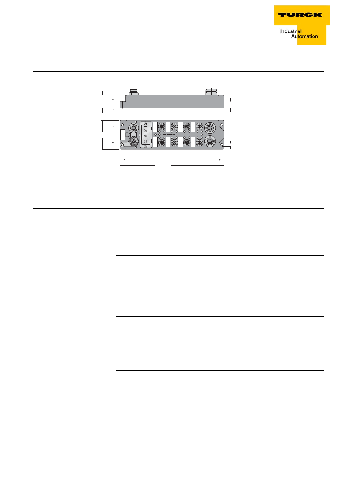
Size 60.4 × 220.5 × 27 mm (B × L × H)
Mounting via 4 through-holes, Ø 4.4 mm
Mounting distance
station to station
≥ 50 mm
Valid for operation in the ambient temperatures
mentioned below, with sufficient ventilation as well
as maximum load (horizontal mounting).
In case of low simultaneity factors and low ambient
temperatures, mounting distances of < 50 mm may
be possible.
Protection class IP67
Vibration test to EN 60068-2-6, IEC 68-2-47
Shock test acc. to EN 60068-2-27
EMC acc. to EN 61131-2
Temperature range
– operating 0 °C to 55 °C (32 °F to 131 °F)
– Storage and transport temperature range -25 °C to 70 °C (-13 °F to 158 °F)
D301271 1013 - FGEN - multi protocol3-4
Page 21
General technical data
0
1
2
3
4
5
6
7
8
9
Power
U
i
U
o
0
1
4
5
37
Bus
ETH1
26
0
1
2
3
4
5
6
7
8
9
0
1
2
3
4
5
6
7
8
9
ETH2
210,5
220,5
C4C5
C6
C7
5,4
60,4 42
C0C1
C2
C3
13
27
13
C9
C8
C11
C10
3.3.2 Dimension drawings
Figure 3-1:
Dimensions for
the FGENstations
3.3.3 LED-displays
Table 3-2:
Dimensions for
the FGENstations
LED Display Meaning Remedy
ETHx green Link established,100 Mbps
Power off U
Ix/Ox green 24 V at input/ output
BUS green Active connection to a master -
green, flashing Ethernet traffic (100 Mbps)
yellow Link established,10 Mbps
yellow flashing Ethernet traffic (10 Mbps)
off No Ethernet link. Check the Ethernet-
connection.
< 18 V DC Check the connected
B
operating voltage.
green U
red U
and UL in the operating range
B
< 18 V DC Check the load voltage.
L
red Overcurrent at the output or at
the sensor supply
D301271 1013 - FGEN - multi protocol
green, flashing ready for operation -
red IP address conflict or restore
mode
red, flashing Blink-/wink-command active -
red/green Autonegotiation and / or
waiting for DHCP- / BootPaddress assignment.
Check the IP-addresses in
the network or wait until the
device is ready.
3-5
Page 22
FGEN – general technical properties
v
4
1
3
2
v
C10 C11
4
1
3
2
1 = TD + (YE)
2 = RD + (WH)
3 = TD (OG)
4 = RD (BU)
Power
U
i
U
o
04
3.4 Connection possibilities
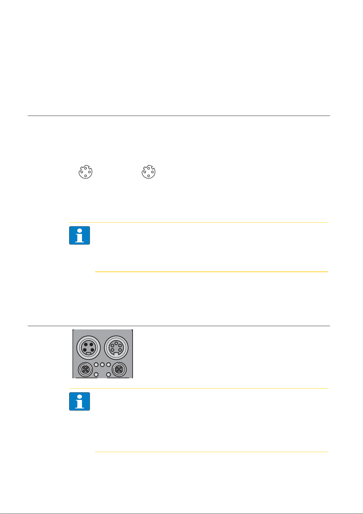
3.4.1 Ethernet
The connection to Ethernet via the integrated auto-crossing switch is done using two 4-pole, D-coded
M12 x 1-Ethernet-female connectors.
Figure 3-2:
Female connectors M12 x 1
Pin assignment
of the M12 x 1-
ETH1 ETH2
female connectors, 4-pole
Ethernet-connection in QC-/FSU-applications
Note
Please observe the following for QuickConnect (QC)- and Fast Start-Up (FSU)-applications:
– do not use a crossover-cable
– ETH1 = connector for incoming Ethernet-line
– ETH2 = connector for outgoing Ethernet-line
3.4.2 Operating/load voltage
The power supply is realized via 7/8" connectors on the module.
These connectors are designed either 4- or 5-pole.
Figure 3-3:
Power supply
Note
The operation voltage (U
voltage falls below the permissible voltage, the outputs are switched off.
U
in.
In case of an undervoltage at U
undervoltage at UB, the "POWER" LED is turned off.
UI = voltage IN
= voltage OUT for supplying the next node
U
O
) and the load voltage (UL) are fed and monitored separately. If the
B
can be switched off. In this case, the module still communicates and the inputs are still read
L
, the "POWER" LED changes from green to red. In case of an
L
D301271 1013 - FGEN - multi protocol3-6
Page 23
Connection possibilities
1 = GND
L
2 = GND
B
3 = PE
4 = U
B
5 = U
L
3
4
5
2
1
wv
3
4
5
2
1
1 = GND
L
2 = GND
B
3 = PE
4 = U
B
5 = U
L
3
4
5
2
1
wv
3
4
5
2
1
1 = GND
2 = GND
3 = FE
4 = U
B
5 = U
L
3
4
5
2
1
3
4
5
2
1
wv
1
2
3
4
1 = Aux +
2 = E +
3 = E
4 = Aux
1
2
3
4
1
2
3
4
1 = U
L
2 = U
B
3 = GND-B
4 = GND-L
1
2
3
4
wv
1
2
3
4
1 = Aux +
2 = E +
3 = E
1
2
3
4
1
2
3
4
1 = U
L
2 = U
B
3 = GND
4 = GND
1
2
3
4
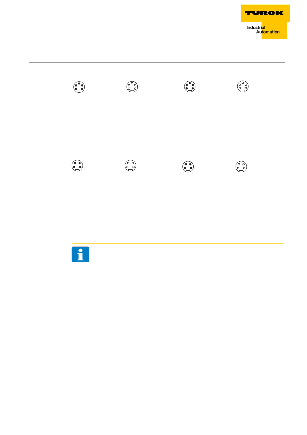
Voltage supply via 7/8’’, 5-pole (FGEN-xxxxx-5xx1)
Figure 3-4:
7/8’’ male and
female,
5-pole
and UB galvanically isolated. No galvanic isolation of UL and UB at the
U
L
Voltage supply via 7/8’’, 4-pole (FGEN-xxxxx-4xx1)
Figure 3-5:
7/8’’ male and
female, 4-pole
FGEN-XSG16-5001
UL and UB galvanically isolated. No galvanic isolation of UL and UB at the
3.4.3 Analog inputs and outputs
The module is equipped throughout with metal M12 connectors for connection of the sensor/actuator
level.
Note
For the pin assignment of the M12-connectors, please refer to the wiring diagrams in the
station-specific chapters of this manual.
U
FGEN-XSG16-4001!
D301271 1013 - FGEN - multi protocol
3-7
Page 24
FGEN – general technical properties
x10
x1
1
2
3
4
5
6
7
8
9
0
1
2
3
4
5
6
7
8
9
0
1
2
3
4
5
6
7
8
9
0
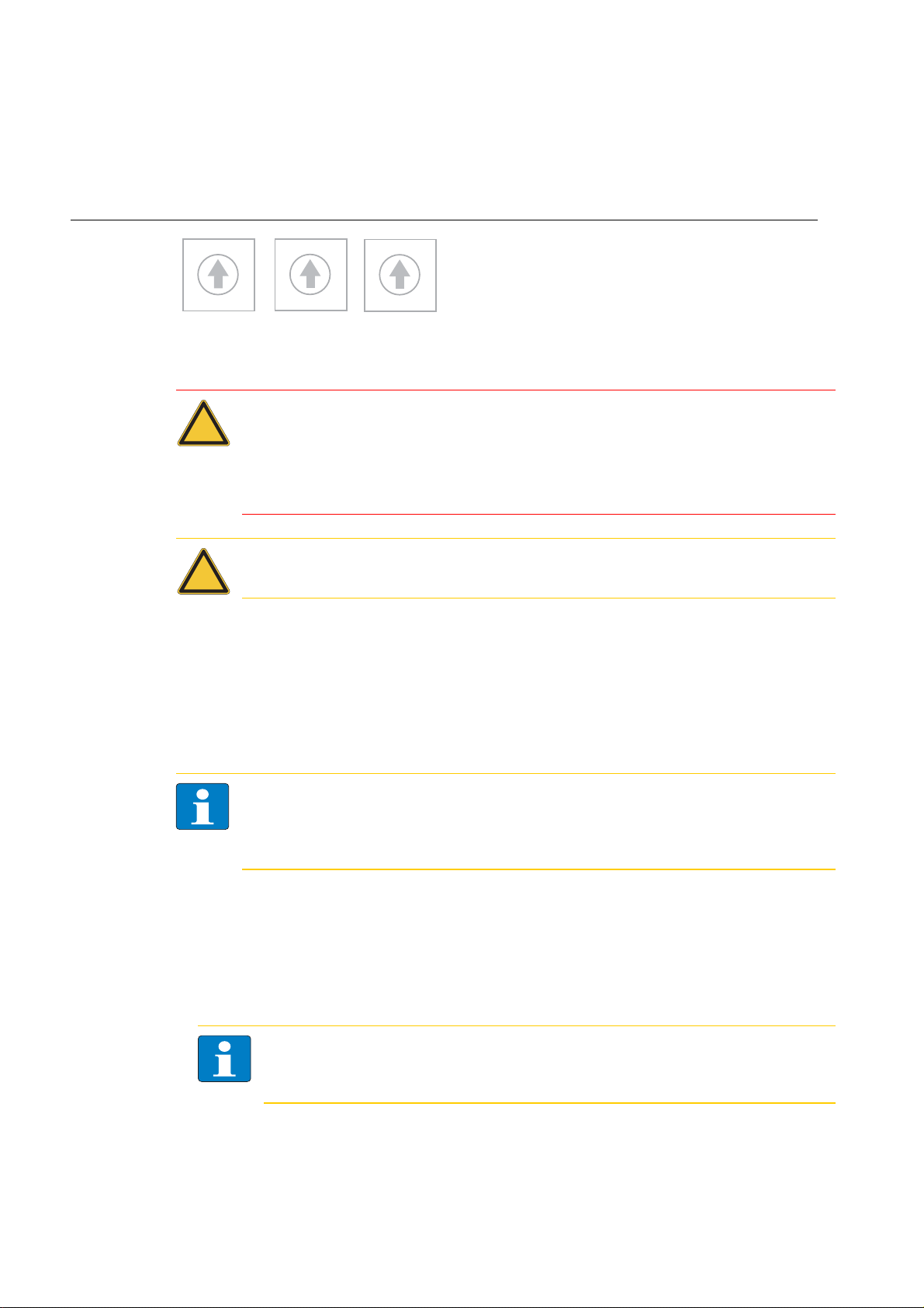
000: 192.168.1.254
1 - 254: static rotary
300: BootP
400: DHCP
500: PGM
600: PGM-DHCP
900: F_Reset
x 100
3.5 Address assignment
Setting the address mode is done through the 3 rotary coding-switches on the gateway.
Figure 3-6:
Decimal rotary
coding-switches
for address
setting
Attention
The cover of the decimal rotary coding-switches must be closed by tightening the screw after
use.
The seal in the cover must not be damaged or slipped.
The protection class IP67 can only be guaranteed when the cover is closed correctly.
Note
After every change of the address-mode, a reset must be carried out.
3.5.1 Default setting of the gateway
The stations' default-settings are as follows:
IP-address 192.168.1.254
subnet mask 255.255.255.0
default gateway 192.168.1.1
Note
The stations can be reset by the user to these default settings at any time.
To reset the module, set the three coding-switches on the gateway to "000" followed by a
power-on reset.
3.5.2 Resetting the IP-address, switch position "000"
By setting the rotary coding switches to "000" followed by a voltage reset, the module is set to the
address 192.168.1.254 for IP-based services (seeDefault setting of the gateway (page 3-8)).
The I/O-ASSISTANT can, for example, communicate with the station in this switch position.
Note
Setting "000" is no operation mode! Please set the device to another mode after having
reset the IP address to the default values.
D301271 1013 - FGEN - multi protocol3-8
Page 25

Address assignment
3.5.3 Address setting via the rotary-mode
switch position: 001 - 254
When using the rotary-mode, the last byte of the station’s IP address can be set via the rotary coding
switches.
Addresses in the range from 0 to 255 can be allocated, whereas 1 is normally reserved for the defaultgateway. 0 and 255 are reserved for broadcast messages in the subnet.
Note
We therefore recommend addresses in the range of 2-254.
3.5.4 Address setting via the mode BootP
switch position: 300
Address setting is carried out by a BootP-server in the network after the start-up of the gateway.
Note
The IP address, as well as the default subnet mask assigned to the station by the BootP-server,
are stored in the station’s EEPROM.
If the station is subsequently switched to rotary- or PGM-mode, the settings carried out via
BootP (IP address, subnet mask, etc) will be read from the module’s EEPROM.
PROFINET
Please assure, that in PROFINET -applications, the address assigned via a BootP-server corresponds to
the address, which is assigned in the configuration tool.
D301271 1013 - FGEN - multi protocol
3-9
Page 26

FGEN – general technical properties
3.5.5 Address setting via the mode DHCP
switch position: 400
Address setting is carried out by a BootP-server in the network after the start-up of the gateway.
Note
The IP address, as well as the default subnet mask assigned to the station by the DHCP-server,
are stored in the station’s EEPROM.
If the station is subsequently switched to rotary- or PGM-mode, the settings carried out via
BootP (IP address, subnet mask, etc) will be read from the module’s EEPROM.
DHCP supports three mechanisms for IP address allocation:
In "automatic allocation", the DHCP-server assigns a permanent IP address to a client.
In "dynamic allocation", DHCP assigns an IP address to a client for a limited period of time. After this
time, or until the client explicitly relinquishes the address, the address can be re-assigned.
In "manual allocation", a client's IP address is assigned by the network administrator, and DHCP is
used simply to convey the assigned address to the client.
PROFINET
Please assure, that in PROFINET -applications, the address assigned via a BootP-server corresponds to
the address, which is assigned in the configuration tool.
3.5.6 Address setting via mode PGM
switch position: 500
The PGM-mode enables access of the software I/O-ASSISTANT to the module’s network settings.
Note
In the PGM-mode, all network settings (IP address, subnet mask, etc.) are send to the module’s
internal EEPROM and stored permanently.
D301271 1013 - FGEN - multi protocol3-10
Page 27

Address assignment
3.5.7 Addressing via mode PGM-DHCP
switch position: 600
The device sends DHCP-requests until a IP-address is assigned (DHCP-server, PROFINET-controller).
The assigned IP-address is stored to the device and the DCHP-client is stopped.
Even after a restart of the device, the device sends no further DHCP-requests.
PROFINET
This mode assures a PROFINET-compliant operation of the modules.
Note
If a DHCP-server is used within the network, problems may occur during IP-assignment.
In this case, both, the DHCP-server as well as the PROFINET-controller (vie DCP), try an IPaddress-assignment.
3.5.8 F_Reset (Factory Reset)
switch position: 900
Setting 900 sets all device-settings back to the default values and deletes all data in the device's internal
flash.
Note
Setting 900 is no operation mode! Please set the device to another mode after having reset
the IP address to the default values.
D301271 1013 - FGEN - multi protocol
3-11
Page 28
FGEN – general technical properties
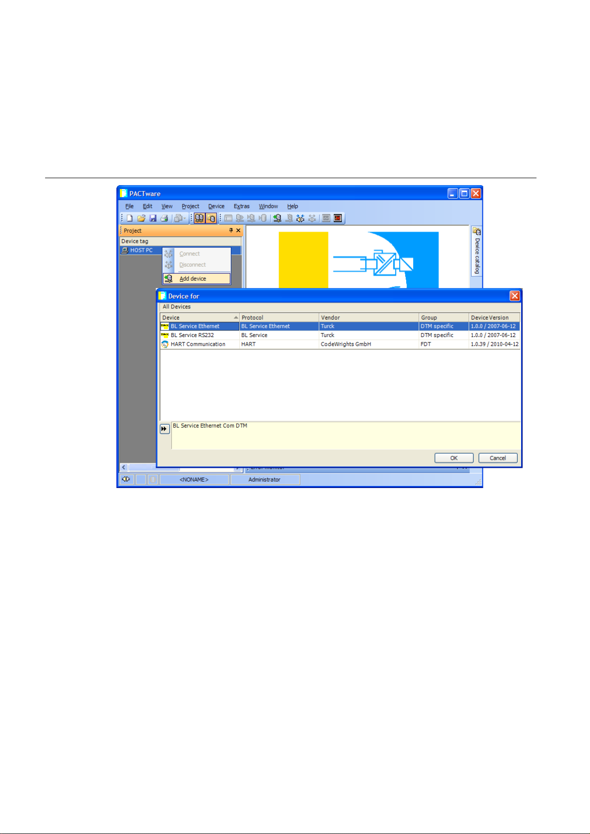
3.5.9 Addressing via I/O-ASSISTANT 3 (FDT/DTM)
The software-tool I/O-ASSISTANT enables direct access to the Ethernet-network via the Ethernet cable.
The IP address, as well as the subnet mask of the TURCK Ethernet stations, can be changed according
to the application by using the Busaddress Management function of the BL Service Ethernet interface
(TCP/IP) in the software I/O-ASSISTANT.
Figure 3-7:
BL Service
Ethernet
D301271 1013 - FGEN - multi protocol3-12
Page 29
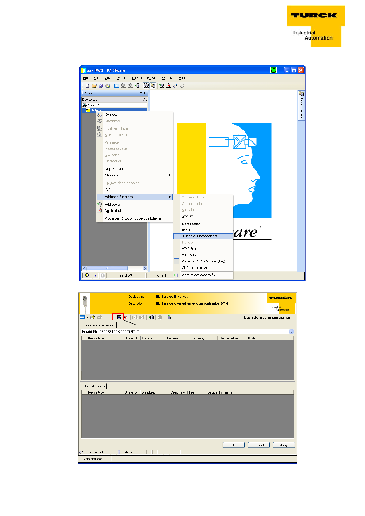
Address assignment
A
Figure 3-8:
Busaddress
management
Figure 3-9:
Searching
networkNodes in the
Busaddress
management
A Search function
in the Busaddress management
D301271 1013 - FGEN - multi protocol
3-13
Page 30
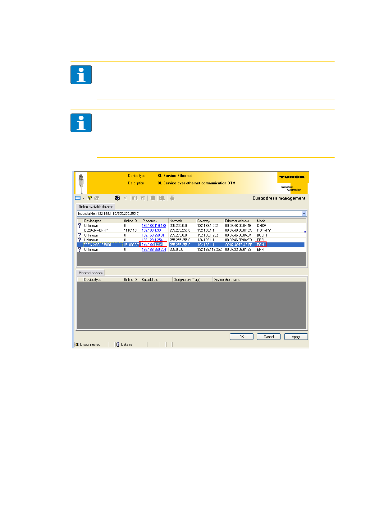
FGEN – general technical properties
Note
The access of the IO-ASSISTANT to the station is only possible, if the station already has an IPaddress and if it is operated in switch position 500 = PGM or 600 = PGM-DHCP-mode (see also
Address assignment (page 3-8)).
Note
When using Windows XP as operating system, difficulties may occur with system-integrated
firewall.
It may inhibit the access of PACTware™ (I/O-ASSISTANT V3) to the Ethernet-network. In this
case, please adapt your firewall respectively or deactivate it.
Figure 3-10:
Specify IP
address
change
D301271 1013 - FGEN - multi protocol3-14
Page 31

SET-button
3.5.10 Addressing via PGM-DHCP
The device's network settings can be changed under "Network Configuration" only by users having
administrator rights.
Further information concerning the web server of the FGEN-devices and it's use can be found under
Web server - remote access/configuration (page 3-16).
Note
The access of the IO-ASSISTANT to the station is only possible, if the station already has an IPaddress and if it is operated in switch position 500 = PGM or 600 = PGM-DHCP-mode (see also
Address assignment (page 3-8)).
Figure 3-11:
Web server with
Network
Configuration
3.6 SET-button
Pushing the SET-button causes a device-restart.
3.7 Device configuration files
The actual device configuration files for the stations can be downloaded from the TURCK-home page
www.turck.com.
D301271 1013 - FGEN - multi protocol
3-15
Page 32

FGEN – general technical properties
3.8 Web server - remote access/configuration
Note
When working with the webserver of the module, it should be assured, that the browser
always reloads the HTML-pages from the module‘s webserver (forced reload). The data
should not be loaded from the browser‘s cache memory.
This guarantees that the data to be shown are always acutal (module type, module status
etc.).
Short-cuts for browser:
Internet Explorer: Shift + F5
Mozilla Firefox: Ctrl + F5
Figure 3-12:
Web server of
the FGENstation
3.8.1 IP address
Open the web server by entering the device's IP-address in your web browser.
IF no IP-address is assigned to the device (DHCP-, BootP-server etc.), then the web server can be opened
using the default IP-address 192.168.1.254.
D301271 1013 - FGEN - multi protocol3-16
Page 33

Web server - remote access/configuration
3.8.2 Access rights
Without administrator rights, data as general product data and diagnosis data are read only.
In order to achieve administrator rights, please log-on to the web server, see Login / password (page
3-17).
3.8.3 Login / password
Login to the web server by using the default-password "password".
The default-password can be changed by the administrator at every time under Change Admin
Password (page 3-20) .
Note
A reset of the device to the default-settings using the switch position
900 "F_Reset" also causes a reset of the password to "password".
Figure 3-13:
Web server
"Home" screen
D301271 1013 - FGEN - multi protocol
3-17
Page 34

FGEN – general technical properties
3.8.4 Network Configuration
On the "Network Configuration"-page, network-relevant settings can be changed.
Figure 3-14:
Web server
"Network
Configuration"
D301271 1013 - FGEN - multi protocol3-18
Page 35

Web server - remote access/configuration
3.8.5 Station Configuration
The "Station Configuration"-page serves for parameterizing the device's fieldbus interface.
Figure 3-15:
Web server
"Station
Configuration"
3.8.6 Station Diagnostics
Diagnostic messages of the device are displayed on the "Station Diagnostics"-page.
3.8.7 Ethernet Statistics
The page "Ethernet Statistics" shows information like the port-status, telegram and error counters etc.
The page can above all be useful for analyzing network problems.
3.8.8 Links
This page contains for example a link to the product page on the TURCK-homepage.
D301271 1013 - FGEN - multi protocol
3-19
Page 36

FGEN – general technical properties
3.8.9 Change Admin Password
Please define an individual password for administrator rights.
Default-password: „password“
Note
A reset of the device to the default-settings using the switch position
900 "F_Reset" also causes a reset of the password to "password".
Figure 3-16:
Change Admin
Password
D301271 1013 - FGEN - multi protocol3-20
Page 37

Web server - remote access/configuration
3.8.10 Parameters
The "Parameters"-page is used to parameterize the station's I/O-channels.
Figure 3-17:
Web server
"Parameters"
D301271 1013 - FGEN - multi protocol
3-21
Page 38

FGEN – general technical properties
3.9 Status and Control Word of the FGEN-stations
The Status as well as the Control Word are mapped into the station's process data.
EtherNet/IP™
In EtherNet/IP™, the mapping can be disabled, see Gateway Class (VSC 100), GW Status register
(page 7-30) and GW Control Register (page 7-30).
Modbus TCP
→ see Register 100Ch: "Station status" (page 9-16)
PROFINET
→ see PROFINET-Error Codes (page 11-4)
3.9.1 Status Word
Byte Bit 7 Bit 6 Bit 5 Bit 4 Bit 3 Bit 2 Bit 1 Bit 0
Status 0
1 - FCE - - CFG COM U
U
L
------
Diag
Warn
B
-
Meaning of the status bits
Table 3-3:
Name Meaning
Meaning of the
status bits
DiagWarn Summarized diagnosis of the device. At least 1 channel sends diagnostics.
U
L
U
B
COM I/O Communication Lost Error
CFG I/O CfgModified Error
FCE Force Mode Active Error
3.9.2 Control Word
The Control Word has no function at the moment, it is reserves for further use.
Load voltage not within the permissible range (18 to 30 V)
System voltage not within the permissible range (18 to 30 V)
No Communication on the module bus.
The I/O-configuration has be changed and is no longer compatible.
The Force Mode is activated, which means, the actual output values may no match the
ones defined and sent by the field bus.
D301271 1013 - FGEN - multi protocol3-22
Page 39

4 Digital inputs FGEN-IM16-x001
4.1 FGEN-IM16-x001 ........................................................................................................................................ 4-2
4.1.1 Technical data ...................................................................................................................................................................................4-2
4.1.2 Wiring diagrams ...............................................................................................................................................................................4-2
– Ethernet ...........................................................................................................................................................................................4-2
– Power supply ................................................................................................................................................................................. 4-2
– Input M12x1 ...................................................................................................................................................................................4-2
4.1.3 Parameters..........................................................................................................................................................................................4-3
4.1.4 Diagnostic message of I/O-channels.........................................................................................................................................4-3
D301271 1013 - FGEN - multi protocol 4-1
Page 40

Digital inputs FGEN-IM16-x001
5 PE
4 BK
1 BN +
3 BU
3 BU
2 WH
v
C0...C7
4.1 FGEN-IM16-x001
The station offers 16 digital inputs for 3-wire pnp sensors.
4.1.1 Technical data
Table 4-1:
Technical data
FGEN-IM16x0001
Type designation FGEN-IM16-x001
Number of channels (16) 3-wire pnp-sensors
Supply (via U
) 18 ... 30 VDC from operating voltage
B
Supply current < 120 mA per connector, short-circuit protected
Switching threshold OFF/ON 2 mA / 4 mA
Low level signal voltage -3 to 5 VDC (EN 61131-2, type 1 and 3)
High level signal voltage 11 to 30 VDC (EN 61131-2, type 1 and 3)
Max. input current 6 mA
Switch-on delay 2.5 ms
Switching frequency
Potential isolation galvanic isolation against U
≤ 500 Hz
and Ethernet
L
Note
General technical data for the products of the FGEN-product line can be found in chapter 3.
4.1.2 Wiring diagrams
Ethernet
→ Ethernet (page 3-6)
Power supply
→ Operating/load voltage (page 3-6)
Input M12x1
Figure 4-1:
Wiring diagram,
input M12x1
D301271 1013 - FGEN - multi protocol4-2
Page 41

FGEN-IM16-x001
4.1.3 Parameters
Table 4-2:
Parameters
A default
setting
Parameter name Value Description
Digital input
(Inv. DIx)
Further information about the parameter data mapping can be found in the fieldbus specific chapters.
EtherNet/IP™: chapter 7.4.4, Digital Versatile Module Class (VSC117) (page 7-34) ff.
Modbus TCP: chapter 9.3.2, Register mapping of the FGEN-stations (page 9-11) ff.
PROFINET: chapter 11.4, Parameters (page 11-5)
0 = normal A
1 = inverted Inverts the digital input signal.
4.1.4 Diagnostic message of I/O-channels
Table 4-3:
Diagnostic
messages
Diagnostics Description
SCSx Short circuit at sensor supply of the respective channel
Further information about the diagnostic data mapping can be found in the fieldbus specific chapters.
EtherNet/IP™: chapter 7.4.4, Process Data Class (VSC102) (page 7-31)
Modbus TCP: chapter 9.3.2, Register mapping of the FGEN-stations (page 9-11) ff.
PROFINET: chapter 11.3, PROFINET-Error Codes (page 11-4)
D301271 1013 - FGEN - multi protocol
4-3
Page 42

Digital inputs FGEN-IM16-x001
D301271 1013 - FGEN - multi protocol4-4
Page 43

5 Digital outputs FGEN-OM16-x001
5.1 FGEN-OM16-x001 ....................................................................................................................................... 5-2
5.1.1 Technical data ...................................................................................................................................................................................5-2
5.1.2 Wiring diagrams ...............................................................................................................................................................................5-2
– Ethernet ...........................................................................................................................................................................................5-2
– Power supply ................................................................................................................................................................................. 5-2
– Input M12x1 ...................................................................................................................................................................................5-2
5.1.3 Parameters..........................................................................................................................................................................................5-3
5.1.4 Diagnostic messages ......................................................................................................................................................................5-3
D301271 1013 - FGEN - multi protocol 5-1
Page 44

Digital outputs FGEN-OM16-x001
5 PE
4 BK +
1
2 WH +
3 BU
v
C0...C7
5.1 FGEN-OM16-x001
The station offers 16 digital inputs for DC actuators.
5.1.1 Technical data
Table 5-1:
Technical data
FGEN-OM16x001
Type designation FGEN-OM16-x001
Number of channels (16) DC actuators
Output voltage 18…30 V DC from load voltage
Output current per channel 2.0 A, short-circuit proof
Load type resistive, inductive, lamp load
Simultaneity factor 0.25 for complete module,
Potential isolation galvanic isolation against U
Note
General technical data for the products of the FGEN-product line can be found in chapter 3.
5.1.2 Wiring diagrams
Ethernet
→ Ethernet (page 3-6)
Power supply
1 × 2 A or 2 × 1 A per connector,
but only max. 9 A total current per module
and Ethernet
B
Figure 5-1:
Wiring diagram,
output M12x1
→ Operating/load voltage (page 3-6)
Input M12x1
D301271 1013 - FGEN - multi protocol5-2
Page 45

FGEN-OM16-x001
5.1.3 Parameters
Table 5-2:
Parameters
A default
setting
Parameter name Value Description
Output on
overcurrent
(SROx)
Further information about the parameters can be found in the fieldbus specific chapters.
EtherNet/IP™: chapter 7.4.4, Digital Versatile Module Class (VSC117) (page 7-34) ff.
Modbus TCP: chapter 9.3.2, Register mapping of the FGEN-stations (page 9-11) ff.
PROFINET: chapter 11.4, Parameters (page 11-5)
5.1.4 Diagnostic messages
Table 5-3:
Diagnostic
messages
Diagnostics Description
SCOx Short circuit at output of the respective channel
0 = activated A The output switches on automatically after an overload.
1 = deactivated The output is switched-off after an overload until a new set-
command is given (fall and rise).
Further information about the diagnostic data mapping can be found in the fieldbus specific chapters.
EtherNet/IP™: chapter 7.4.3, Process Data Class (VSC102) (page 7-31) ff.
Modbus TCP: chapter 9.3.2, Register mapping of the FGEN-stations (page 9-11) ff.
PROFINET: chapter 11.3, PROFINET-Error Codes (page 11-4)
D301271 1013 - FGEN - multi protocol
5-3
Page 46

Digital outputs FGEN-OM16-x001
D301271 1013 - FGEN - multi protocol5-4
Page 47

6 Digital in-/outputs FGEN-IOM88-x001, FGEN-XSG16-x001
6.1 FGEN-IOM88-x001...................................................................................................................................... 6-2
6.1.1 Technical data ...................................................................................................................................................................................6-2
6.1.2 Wiring diagrams ...............................................................................................................................................................................6-3
– Ethernet ...........................................................................................................................................................................................6-3
– Power supply ................................................................................................................................................................................. 6-3
6.1.3 Parameters..........................................................................................................................................................................................6-3
6.1.4 Diagnostic messages ......................................................................................................................................................................6-4
6.2 FGEN-XSG16-000x...................................................................................................................................... 6-5
6.2.1 Technical data ...................................................................................................................................................................................6-5
6.2.2 Wiring diagrams ...............................................................................................................................................................................6-6
– Ethernet ...........................................................................................................................................................................................6-6
– Power supply ................................................................................................................................................................................. 6-6
6.2.3 Parameters..........................................................................................................................................................................................6-7
6.2.4 Diagnostic messages ......................................................................................................................................................................6-8
D301271 1013 - FGEN - multi protocol 6-1
Page 48

Digital in-/outputs FGEN-IOM88-x001, FGEN-XSG16-x001
6.1 FGEN-IOM88-x001
The station offers 8 digital inputs for 3-wire pnp sensors and 8 digital outputs for DC actuators.
6.1.1 Technical data
Table 6-1:
Technical data
FGEN-IOM88x001
Designation FGEN-IOM88-x001
Inputs (8) 3-wire pnp-sensors
Supply (via U
) 18... 30 V DC from operating voltage
B
Supply current < 120 mA per connector, short-circuit protected
Switching threshold OFF/ON 2 mA / 4 mA
Low level signal voltage -3 to 5 VDC (EN 61131-2, type 1 and 3)
High level signal voltage 11 to 30 VDC (EN 61131-2, type 1 and 3)
Max. input current 6 mA
Switch-on delay 2.5 ms
Switching frequency
Potential isolation galvanic isolation against U
≤ 500 Hz
and Ethernet
L
Outputs (8) DC actuators
Output voltage 18…30 V DC from load voltage
Output current per channel 2.0 A, short-circuit proof
Load type resistive, inductive, lamp load
Simultaneity factor 0.25 for complete module,
1 × 2 A or 2 × 1 A per connector,
but only max. 9 A total current per module
Potential isolation galvanic isolation against U
Note
General technical data for the products of the FGEN-product line can be found in chapter 3.
and Ethernet
B
D301271 1013 - FGEN - multi protocol6-2
Page 49

FGEN-IOM88-x001
5 PE
4 BK
1 BN +
3 BU
3 BU
2 WH
v
C0...C3
5 PE
4 BK +
1
2 WH +
3 BU
v
C4...C7
6.1.2 Wiring diagrams
Ethernet
→ Ethernet (page 3-6)
Power supply
→ Operating/load voltage (page 3-6)
Figure 6-1:
Wiring diagram
input M12 x 1
Figure 6-2:
Wiring diagram
output M12 x 1
6.1.3 Parameters
Table 6-2:
Parameters
A default
setting
Parameter name Value Description
Digital input
(Inv. DIx)
Output on
overcurrent
(SROx)
Further information about the parameter data mapping can be found in the fieldbus specific chapters.
EtherNet/IP™: chapter 7.4.4, Digital Versatile Module Class (VSC117) (page 7-34) ff.
Modbus TCP: chapter 9.3.2, Register mapping of the FGEN-stations (page 9-11) ff.
PROFINET: chapter 11.4, Parameters (page 11-5)
0 = normal A
1 = inverted Inverts the digital input signal.
0 = activated
A The output switches on automatically after an overload.
1 = deactivated The output is manually switched-off after an overload.until
a new set-command is given (rise and fall).
D301271 1013 - FGEN - multi protocol
6-3
Page 50

Digital in-/outputs FGEN-IOM88-x001, FGEN-XSG16-x001
6.1.4 Diagnostic messages
Table 6-3:
Diagnostic
messages
Diagnostics Description
SCSx Short circuit at sensor supply of the respective channel
SCOx Short circuit at output of the respective channel
Further information about the diagnostic data mapping can be found in the fieldbus specific chapters.
EtherNet/IP™: chapter 7.3.3, Process data mapping FGEN-IM16-x001 (page 7-11) ff.
Modbus TCP: chapter 9.3.2, Register mapping of the FGEN-stations (page 9-11) ff.
PROFINET: chapter 11.3, PROFINET-Error Codes (page 11-4)
D301271 1013 - FGEN - multi protocol6-4
Page 51

FGEN-XSG16-000x
6.2 FGEN-XSG16-000x
The station is equipped with 16 channels, which can be configured individually, depending on the
specific application requirements. Up to sixteen 3 wire pnp sensors or sixteen DC actuators with a
maximum output current of 1.4 A per output can be connected.
6.2.1 Technical data
Table 6-4:
Technical data
FGEN-XSG16x00x
Designation FGEN-XSG16-x001
Inputs (16) 3-wire pnp-sensors
Supply (via U
) 18 ... 30 V DC from operating voltage
B
Supply current < 120 mA per connector, short-circuit protected
Switching threshold OFF/ON 2 mA / 4 mA
Low level signal voltage -3 to 5 VDC (EN 61131-2, type 1 and 3)
High level signal voltage 11 to 30 VDC (EN 61131-2, type 1 and 3)
Max. input current 6 mA
Switch-on delay 2.5 ms
Switching frequency
Potential isolation galvanic isolation against U
≤ 500 Hz
and Ethernet
L
Outputs (16) DC actuators
Output voltage 18…30 V DC from load voltage
Output current per channel 2.0 A, short-circuit proof
Load type resistive, inductive, lamp load
Simultaneity factor 0.25 for complete module,
1 × 2 A or 2 × 1 A per connector,
but only max. 9 A total current per module
Potential isolation galvanic isolation against U
Note
General technical data for the products of the FGEN-product line can be found in chapter 3.
and Ethernet
B
D301271 1013 - FGEN - multi protocol
6-5
Page 52

Digital in-/outputs FGEN-IOM88-x001, FGEN-XSG16-x001
5 PE
4 BK +
1
2 WH +
3 BU –
5 PE
4 BK
1 BN +
3 BU –
3 BU –
2 WH
5
PE
4 ( ) BK
1 (+) BN
3 () BU
2
5
PE
4 (+) BK
1 (+) BN
3 () BU
2 ( ) WH
6.2.2 Wiring diagrams
Ethernet
→ Ethernet (page 3-6)
Power supply
→ Operating/load voltage (page 3-6)
Figure 6-3:
Wiring
diagrams
Connection of 2 actuators:
Connection of 2 sensors:
Combination of sensor and actuator:
D301271 1013 - FGEN - multi protocol6-6
Page 53

FGEN-XSG16-000x
6.2.3 Parameters
Table 6-5:
Parameters
A default
setting
Parameter name Value Description
Digital input
(Inv. DI)
Output on
overcurrent
(SROx)
0 = normal A
1 = inverted Inverts the digital input signal.
0 = activated
A The output switches on automatically after an overload.
1 = deactivated The output is manually switched-off after an overload.until
a new set-command is given (rise and fall).
output 0 = deactivated
1 = activated
A
Further information about the parameter data mapping can be found in the fieldbus specific chapters.
EtherNet/IP™: chapter 7.3.3, Process data mapping FGEN-XSG16-x001 (page 7-17) ff.
Modbus TCP: chapter 9.3.2, Register mapping of the FGEN-stations (page 9-11) ff.
PROFINET: chapter 11.4, Parameters (page 11-5)
D301271 1013 - FGEN - multi protocol
6-7
Page 54

Digital in-/outputs FGEN-IOM88-x001, FGEN-XSG16-x001
6.2.4 Diagnostic messages
Table 6-6:
Diagnostic
messages
Diagnostics Description
SCSx Short circuit at sensor supply of the respective channel
SCOx Short circuit at output of the respective channel
Further information about the diagnostic data mapping can be found in the fieldbus specific chapters.
EtherNet/IP™: chapter 7.3.3, Process data mapping FGEN-IM16-x001 (page 7-11) ff.
Modbus TCP: chapter 9.3.2, Register mapping of the FGEN-stations (page 9-11) ff.
PROFINET: chapter 11.3, PROFINET-Error Codes (page 11-4)
D301271 1013 - FGEN - multi protocol6-8
Page 55

7 Implementation of EtherNet/IP™
7.1 EtherNet/IP Communications Profile ....................................................................................................... 7-2
7.1.1 I/O Messages......................................................................................................................................................................................7-2
7.1.2 Explicit Messages..............................................................................................................................................................................7-2
7.1.3 Communications profile of FGEN ............................................................................................................................................... 7-2
– Unicast .............................................................................................................................................................................................7-2
– Multicast .......................................................................................................................................................................................... 7-2
– COS I/O Connection ....................................................................................................................................................................7-3
– Cyclic I/O Connection .................................................................................................................................................................7-3
– UCMM...............................................................................................................................................................................................7-3
– Connected Explicit Messaging ................................................................................................................................................7-3
7.2 QC - QuickConnect ..................................................................................................................................... 7-4
7.2.1 General.................................................................................................................................................................................................7-4
7.2.2 QuickConnect in FGEN ...................................................................................................................................................................7-4
– QuickConnect via Configuration Assembly........................................................................................................................7-5
– Quick Connect via Class Instance Attribute........................................................................................................................7-5
7.3 Classes and Instances of the EtherNet/IP™-stations................................................................................ 7-6
7.3.1 EtherNet/IP™ Standard Classes ...................................................................................................................................................7-6
7.3.2 PROFINETIdentity Object (0×01) ................................................................................................................................................ 7-7
7.3.3 Assembly Object (0×04)................................................................................................................................................................. 7-9
– Configuration Assembly ............................................................................................................................................................7-9
– Process data instances ............................................................................................................................................................ 7-10
– Process data mapping FGEN-IM16-x001 .......................................................................................................................... 7-11
– Process data mapping FGEN-OM16-x001........................................................................................................................7-13
– Process data mapping FGEN-IOM88-x001....................................................................................................................... 7-15
– Process data mapping FGEN-XSG16-x001....................................................................................................................... 7-17
– Meaning of Process data bits ................................................................................................................................................ 7-20
7.3.4 Connection Manager Object (0×06)....................................................................................................................................... 7-21
7.3.5 TCP/IP Interface Object (0×F5) ................................................................................................................................................. 7-22
7.3.6 Ethernet Link Object (0×F6) ...................................................................................................................................................... 7-26
7.4 VSC-Vendor Specific Classes ................................................................................................................... 7-28
7.4.1 Class instance of the VSC............................................................................................................................................................ 7-28
7.4.2 Gateway Class (VSC 100).............................................................................................................................................................7-29
– Class instance ............................................................................................................................................................................. 7-29
– Object Instance 1....................................................................................................................................................................... 7-29
– Object Instance 2....................................................................................................................................................................... 7-30
7.4.3 Process Data Class (VSC102)...................................................................................................................................................... 7-31
– Class instance ............................................................................................................................................................................. 7-31
– Object instance 1, standard input process data (compressed) ............................................................................... 7-31
– Object Instance 3, diagnostic instance ............................................................................................................................. 7-32
– Object Instance 4, COS/CYCLIC instance .......................................................................................................................... 7-33
7.4.4 Digital Versatile Module Class (VSC117) ............................................................................................................................... 7-34
– Object Instance .......................................................................................................................................................................... 7-34
7.4.5 Miscellaneous Parameters Class (VSC 126) .......................................................................................................................... 7-35
– Instance 1 / Instance 2 ............................................................................................................................................................. 7-35
7.5 Diagnostic messages via process data ................................................................................................... 7-36
7.5.1 Summarized Diagnostics............................................................................................................................................................ 7-36
7.5.2 Scheduled Diagnostics (manufacturer specific diagnosis) ............................................................................................ 7-36
D301271 1013 - FGEN - multi protocol 7-1
Page 56

Implementation of EtherNet/IP™
7.1 EtherNet/IP Communications Profile
EtherNet/IP is based on a connection-oriented communication model. This means that it is only
possible to exchange data via specified connections assigned to the devices.
Communication between the nodes in the EtherNet/IP network can be carried out either via I/O
Messages or Explicit Messages.
7.1.1 I/O Messages
I/O Messages serve to exchange high priority process and application data over the network.
Communication between the slaves in the EtherNet/IP network is carried out according to the Server/
Client Model,
which means a producing application transmits data to another or a number of consuming
applications. It is quite possible that information is passed to a number of Application Objects in a
single device.
7.1.2 Explicit Messages
Explicit Messages are used to transmit low-priority configuration data, general management data or
diagnostic data between two specific devices. This is a point-to-point connection in a Server/Client
System that requires a request from a client always to be confirmed by a response from the server.
Message Router Request
Consists of a service code, path size value, a message router path and service data. An EPATH is used
in the message router path to indicate the target object.
Message Router Response
Consists of a service field with the most significant bit set. This is an echo of the service code in the
request message with the most significant bit set. A reserved byte follows the service code, which is
followed by the General Status code.
7.1.3 Communications profile of FGEN
FGEN behaves as an EtherNet/IP Server in the network; the scanner of the higher-level controller
operates as a EtherNet/IP Client.
The following EtherNet/IP communications types are supported:
Unicast
Multicast
Cyclic Connection
Unconnected (UCMM) Explicit Messaging
Connected Explicit Messaging
Unicast
A point-to-point connection that exists between two nodes only.
Multicast
A packet with a special destination address, which multiple nodes on the network may be willing to
receive.
D301271 1013 - FGEN - multi protocol7-2
Page 57

EtherNet/IP Communications Profile
COS I/O Connection
COS (Change Of State) I/O Connections establish event-controlled connections. This means that the
EtherNet/IP devices generate messages as soon as a change of status occurs.
Cyclic I/O Connection
Messages are triggered time-controlled in Cyclic I/O connections by means of a time generator.
UCMM
The EtherNet/IP gateway offers the option of establishing explicit messaging via the UCMM port
(Unconnected Message Manager Port).
UCMM-based explicit messaging is normally used for random, non-periodic requests.
It is not recommended for frequent messaging because the UCMM input queue in a product is typically
limited to just a few messages. Once this limit is reached, subsequent requests are ignored and must
be retried.
Connected Explicit Messaging
CIP is a connection-based system. For most communications between nodes, a connection is used.
A connection is a path or a virtual circuit between two or more end points in a system. The purpose is
to transfer data in the most efficient manner possible.
The Connection ID is a number that is associated with a communication relationship. Receiving nodes
decode this key to know whether they must accept the data or not.
D301271 1013 - FGEN - multi protocol
7-3
Page 58

Implementation of EtherNet/IP™
7.2 QC - QuickConnect
7.2.1 General
QuickConnect enables a PLC to build up connections to EtherNet/IP™-nodes in less than 300 ms after
switching-on the power supply for the EtherNet/IP™-network. This fast start up of devices is above all
necessary for robotic tool changes for example in the automobile industry.
Note
For correct cabling with FGEN in QC-applications, see Ethernet-connection in QC-/FSU-
applications (page 3-6).
7.2.2 QuickConnect in FGEN
TURCK FGEN-stations support QuickConnect.
QuickConnect is activated:
via the configuration data in the PLC-program per
Assembly Class 0×04, Configuration Assembly 106, bit 9 = 1
(see also chapter 8, Activating QuickConnect (page 8-13)
or
via Class Instance Attribute in
TCP/IP Interface Object (0×F5), instance 1, attribute 12 (0×C0)
Note
Activating the QuickConnect-function leads to the automatical setting of all necessary portproperties:
Autonegotiation
transmission speed
Duplex
Topology
AutoMDIX
= deactivated
= 100BaseT
= full duplex
= linear
= deactivated
D301271 1013 - FGEN - multi protocol7-4
Page 59

QC - QuickConnect
QuickConnect via Configuration Assembly
The Configuration Assembly is part of the Assembly Class of the device and is defined during the
station's configuration in the RS Logix-software by Rockwell Automation.
Figure 7-1:
Configuration
Assembly
Note
Further information about the configuration of FGEN-stations in the Rockwell software
RS Logix can be found in chapter 8, Application example: FGEN for EtherNet/IP™ with
Allen Bradley PLC and RS Logix 5000.
Quick Connect via Class Instance Attribute
Activate QuickConnect via Class Instance Attribute using the following setting:
Class Instance Attribute Value
245
(0xF5)
1
(0x01)
12
(0x0C)
0: disabled (default)
1: enabled
D301271 1013 - FGEN - multi protocol
7-5
Page 60

Implementation of EtherNet/IP™
7.3 Classes and Instances of the EtherNet/IP™-stations
7.3.1 EtherNet/IP™ Standard Classes
The FGEN stations support the following EtherNet/IP™ Standard Classes in accordance with the CIP
specification.
Table 7-1:
EtherNet/IP™
Standard Classes
Class Code Object name
01 (0×01)
04 (0×04)
06 (0×06)
245 (0×F5)
246 (0×F6)
Identity Object (0×01)
Assembly Object (0×04)
Connection Manager Object (0×06)
TCP/IP Interface Object (0×F5)
Ethernet Link Object (0×F6)
D301271 1013 - FGEN - multi protocol7-6
Page 61

Classes and Instances of the EtherNet/IP™-stations
7.3.2 Identity Object (0×01)
The following description of the Ethernet Link Object is taken from the CIP specification, Vol. 2, Rev. 2.1
by ODVA & ControlNet International Ltd. and adapted to FGEN.
Class Attributes
Table 7-2:
Class Attributes
Table 7-3:
Instance
attributes
Attr. No. Attribute name Get/
Set
1 (0×01)
2 (0×02)
6 (0×06)
7 (0×07)
REVISION G UINT 1
MAX OBJECT INSTANCE G UINT 1
MAX CLASS ATTRIBUTE G UINT 7
MAX INSTANCE ATTRIBUTE G UINT 7
Instance attributes
Attr. No. Attribute name Get/
Type Description
Set
1 (0×01)
VENDOR G UINT Contains the vendor ID.
TURCK = 48
2 (0×02)
PRODUCT TYPE G UINT Indicates the general type of product.
Communications Adapter
= 0×0C
12
dez
3 (0×03)
PRODUCT CODE G UINT Identifies a particular product within a device
type.
Default: 27247
dec =
6A6F
Type Value
4 (0×04)
5 (0×05)
6 (0×06)
7 (0×07)
REVISION
Major Minor
G STRUCT
OF:
USINT
USINT
Revision of the item the Identity Object is
representing.
0x01
0x06
DEVICE STATUS G WORD See Table 7-4: Device Status
SERIAL NUMBER G UDINT Contains the ident-no. of the product (3 last
bytes of the MAC-ID).
PRODUCT NAME
G STRUCT
OF:
e. g.:
FGEN-XSG16-5001
LENGTH
NAME
USINT
STRING
[13]
D301271 1013 - FGEN - multi protocol
7-7
Page 62

Implementation of EtherNet/IP™
Device Status
Table 7-4:
Device Status
Table 7-5:
Common services
Bit Name Definition
0 to 1
2
reserved Default = 0
Configured TRUE = 1
→ The application of the device has been configured
(≠ default-settings).
3
4 to 7
reserved Default = 0
Extended Device
Status
0011 = no I/O connection established
0110 = At least one I/O connection in run mode
0111 = At least one I/O connection established, all in IDLE
mode
All other settings = reserved
8 to 15
reserved Default = 0
Common services
Service code Class Instance Service name
01 (0x01)
yes yes Get_Attribute_All
Returns a predefined list of the object‘s attributes.
05 (0x05)
no yes Reset
Starts the reset service for the device.
14 (0x0E)
16 (0x10)
yes yes Get_Attribute_Single
Returns the contents of a specified attribute.
no no Set_Attribute_Single
Modifies a single attribute.
D301271 1013 - FGEN - multi protocol7-8
Page 63

Classes and Instances of the EtherNet/IP™-stations
7.3.3 Assembly Object (0×04)
Assembly Objects bind attributes of multiple objects to allow data to or from each object to be sent or
received over a single connection.
The following description of the Ethernet Link Object is taken from the CIP specification, Vol. 2, Rev. 2.1
by ODVA & ControlNet International Ltd. and adapted to FGEN.
Class attributes
Table 7-6:
Class attributes
Table 7-7:
Instance
attributes
Table 7-8:
Common services
Attr. No. Attribute name Get/
Set
1 (0×01)
2 (0×02)
REVISION G UINT 2
MAX OBJECT INSTANCE G UINT 104
Instance attributes
Attr. No. Attribute name Get/
Type Description
Set
3 (0×03)
DATA S ARRAY OF
BYTE
4 (0×04)
SIZE G UINT UINT Number of bytes in attr. 3
256 or variable
Common services
Service code Class Instance Service name
01 (0x01)
14 (0x0E)
yes yes Get_Attribute_All
no yes Get_Attribute_Single
Type Value
Configuration Assembly
Instance 106
14 byte configuration data
Byte 9, bit 1 is used to activate QuickConnect in the station (see also QuickConnect via Configuration
Assembly (page 7-5)).
D301271 1013 - FGEN - multi protocol
7-9
Page 64

Implementation of EtherNet/IP™
Process data instances
Instance 101
Contains the station’s input data (static length 256 bytes).
2 Bytes status information (see page 3-22)
+ process data
Instance 102
Contains the station’s output data (static length 256 bytes).
2 Bytes Control data (mapped, but not defined)
+ process data
Instance 103 und Instance 104
In- and output assembly instances with variable assembly sizes. The assembly size is pre-calculated to
support the stations I/O-configuration, enabled diagnostics, etc.
input assembly instance: 103
output assembly instance: 104
The effective size of the Assembly Instance can be determined using the Assembly Object (instance
0×67, attribute 0x04) and can be from 2 to 496 bytes large.
D301271 1013 - FGEN - multi protocol7-10
Page 65

Classes and Instances of the EtherNet/IP™-stations
Process data mapping FGEN-IM16-x001
No diagnostic message,
Status- and control-word can be deactivated, see page 3-22.
IN = 4 Byte
OUT = 2 Byte
IN Byte Bit 7 Bit 6 Bit 5 Bit 4 Bit 3 Bit 2 Bit 1 Bit 0
Status 0
-------
1-FCE--CFGCOMU
Inputs 2 DI7
C3P2
3DI15
C7P2
DI6
C3P4
DI14
C7P4
OUT Byte Bit 7 Bit 6 Bit 5 Bit 4 Bit 3 Bit 2 Bit 1 Bit 0
Control 0 Control word (MSB)
1Control word (LSB)
DI5
C0P2
DI13
C6P2
DI4
C2P4
DI12
C6P4
DI3
C1P2
DI11
C5P2
DI2
C1P4
DI10
C5P4
B
DI1
C0P2
DI9
C4P2
Diag
Warn
-
DI0
C0P4
DI8
C4P4
→ Meaning of Process data bits (page 7-20)
Summarized diagnostics activated, see page 7-36
IN = 6 Byte
OUT = 2 Byte
IN Byte Bit 7 Bit 6 Bit 5 Bit 4 Bit 3 Bit 2 Bit 1 Bit 0
Status 0
1-FCE--CFGCOMU
Inputs 2 DI7
3DI15
Diagnos
tics
4 -------I/O Diag
5 --------
-------
B
C3P2
C7P2
DI6
C3P4
DI14
C7P4
DI5
C0P2
DI13
C6P2
DI4
C2P4
DI12
C6P4
DI3
C1P2
DI11
C5P2
DI2
C1P4
DI10
C5P4
DI1
C0P2
DI9
C4P2
OUT Byte Bit 7 Bit 6 Bit 5 Bit 4 Bit 3 Bit 2 Bit 1 Bit 0
Control 0 Control word (MSB)
1Control word (LSB)
Diag
Warn
-
DI0
C0P4
DI8
C4P4
→ Meaning of Process data bits (page 7-20)
D301271 1013 - FGEN - multi protocol
7-11
Page 66

Implementation of EtherNet/IP™
Manufacturer specific (scheduled diagnostics) activated, see page 7-36
IN = 8 Byte
OUT = 2 Byte
IN Byte Bit 7 Bit 6 Bit 5 Bit 4 Bit 3 Bit 2 Bit 1 Bit 0
Status 0
1 - FCE - - CFG COM U
Inputs 2 DI7
3DI15
Diagnos
tics
4 -------I/O Diag
5
6 SCS7 SCS6 SCS5 SCS4 SCS3 SCS2 SCS1 SCS0
7 --------
OUT Byte Bit 7 Bit 6 Bit 5 Bit 4 Bit 3 Bit 2 Bit 1 Bit 0
Control 0 Control word (MSB)
1 Control word (LSB)
-------
B
DI6
C3P2
C3P4
DI14
C7P2
C7P4
--
DI5
C0P2
DI13
C6P2
Sched
Diag
DI4
C2P4
DI12
C6P4
DI3
C1P2
DI11
C5P2
DI2
C1P4
DI10
C5P4
DI1
C0P2
DI9
C4P2
-----
Diag
Warn
-
DI0
C0P4
DI8
C4P4
→ Meaning of Process data bits (page 7-20)
D301271 1013 - FGEN - multi protocol7-12
Page 67

Classes and Instances of the EtherNet/IP™-stations
Process data mapping FGEN-OM16-x001
No diagnostic message,
Status- and control-word can be deactivated, see page 3-22.
IN = 2 Byte
OUT = 4 Byte
IN Byte Bit 7 Bit 6 Bit 5 Bit 4 Bit 3 Bit 2 Bit 1 Bit 0
Status 0
U
L
------
1-FCE--CFGCOMU
OUT Byte Bit 7 Bit 6 Bit 5 Bit 4 Bit 3 Bit 2 Bit 1 Bit 0
Control 0 Control word (MSB)
1Control word (LSB)
Outputs 2 DO7
C3P2
3DO15
C7P2
DO6
C3P4
DO14
C7P4
DO5
C2P2
DO13
C6P2
DO4
C2P4
DO12
C6P4
DO3
C1P2
DO11
C5P2
DO2
C1P4
DO10
C5P4
B
DO1
C0P2
DO9
C4P2
Diag
Warn
-
DO0
C0P4
DO8
C4P4
→ Meaning of Process data bits (page 7-20)
Summarized diagnostics activated, see page 7-36
IN = 4 Byte
OUT = 4 Byte
IN Byte Bit 7 Bit 6 Bit 5 Bit 4 Bit 3 Bit 2 Bit 1 Bit 0
Status 0
Diagnos
tics
1-FCE--CFGCOMU
4 -------I/O Diag
5 --------
U
L
------
B
OUT Byte Bit 7 Bit 6 Bit 5 Bit 4 Bit 3 Bit 2 Bit 1 Bit 0
Control 0 Control word (MSB)
1Control word (LSB)
Outputs 2 DO7
C3P2
3DO15
C7P2
DO6
C3P4
DO14
C7P4
DO5
C2P2
DO13
C6P2
DO4
C2P4
DO12
C6P4
DO3
C1P2
DO11
C5P2
DO2
C1P4
DO10
C5P4
DO1
C0P2
DO9
C4P2
Diag
Warn
-
DO0
C0P4
DO8
C4P4
→ Meaning of Process data bits (page 7-20)
D301271 1013 - FGEN - multi protocol
7-13
Page 68

Implementation of EtherNet/IP™
Manufacturer specific (scheduled diagnostics) activated, see page 7-36
IN = 8 Byte
OUT = 4 Byte
IN Byte Bit 7 Bit 6 Bit 5 Bit 4 Bit 3 Bit 2 Bit 1 Bit 0
Status 0
1 - FCE - - CFG COM U
Diagnos
tics
2 -------I/O Diag
3
4--------
5 SCO7 SCO6 SCO5 SCO4 SCO3 SCO2 SCO1 SCO0
6 SCO15 SCO14 SCO13 SCO12 SCO11 SCO10 SCO9 SCO8
7 --------
OUT Byte Bit 7 Bit 6 Bit 5 Bit 4 Bit 3 Bit 2 Bit 1 Bit 0
Control 0 Control word (MSB)
1 Control word (LSB)
Outputs 2 DO7
3DO15
U
L
------
--
DO6
C3P2
C3P4
DO14
C7P2
C7P4
Sched
Diag
DO5
C2P2
DO13
C6P2
Diag
Warn
B
-
-----
DO4
C2P4
DO12
C6P4
DO3
C1P2
DO11
C5P2
DO2
C1P4
DO10
C5P4
DO1
C0P2
DO9
C4P2
DO0
C0P4
DO8
C4P4
→ Meaning of Process data bits (page 7-20)
D301271 1013 - FGEN - multi protocol7-14
Page 69

Classes and Instances of the EtherNet/IP™-stations
Process data mapping FGEN-IOM88-x001
No diagnostic message,
Status- and control-word can be deactivated, see page 3-22.
IN = 4 Byte
OUT = 4 Byte
IN Byte Bit 7 Bit 6 Bit 5 Bit 4 Bit 3 Bit 2 Bit 1 Bit 0
Status 0
U
L
------
1-FCE--CFGCOMU
Inputs 2 DI7
C3P2
DI6
C3P4
3 --------
OUT Byte Bit 7 Bit 6 Bit 5 Bit 4 Bit 3 Bit 2 Bit 1 Bit 0
Control 0 Control word (MSB)
1Control word (LSB)
Outputs 2 DO7
C3P2
DO6
C3P4
3 --------
DI5
C2P2
DO5
C2P2
DI4
C2P4
DO4
C2P4
DI3
C1P2
DO3
C1P2
DI2
C1P4
DO2
C1P4
B
DI1
C0P2
DO1
C0P2
Diag
Warn
-
DI0
C0P4
DO0
C0P4
→ Meaning of Process data bits (page 7-20)
Summarized diagnostics activated, see page 7-36
IN = 6 Byte
OUT = 4 Byte
IN Byte Bit 7 Bit 6 Bit 5 Bit 4 Bit 3 Bit 2 Bit 1 Bit 0
Status 0
1-FCE--CFGCOMU
Inputs 2 DI7
U
L
C3P2
------
B
DI6
C3P4
DI5
C2P2
DI4
C2P4
DI3
C1P2
DI2
C1P4
DI1 C0P2
3 --------
Diagnos
tics
4 -------I/O Diag
5 --------
OUT Byte Bit 7 Bit 6 Bit 5 Bit 4 Bit 3 Bit 2 Bit 1 Bit 0
Control 0 Control word (MSB)
1Control word (LSB)
Outputs 2 DO7
C3P2
DO6
C3P4
DO5
C2P2
DO4
C2P4
DO3
C1P2
DO2
C1P4
DO1
C0P2
3 --------
Diag
Warn
-
DI0
C0P4
DO0
C0P4
→ Meaning of Process data bits (page 7-20)
D301271 1013 - FGEN - multi protocol
7-15
Page 70

Implementation of EtherNet/IP™
Manufacturer specific (scheduled diagnostics) activated, see page 7-36
IN = 8 Byte
OUT = 4 Byte
IN Byte Bit 7 Bit 6 Bit 5 Bit 4 Bit 3 Bit 2 Bit 1 Bit 0
Status 0
1 - FCE - - CFG COM U
Inputs 2 DI7
Diagnos
tics
3 --------
4 -------I/O Diag
5
6 - - - - SCS3 SCS2 SCS1 SCS0
7 SCO7 SCO6 SCO5 SCO4 SCO3 SCO2 SCO1 SCO0
OUT Byte Bit 7 Bit 6 Bit 5 Bit 4 Bit 3 Bit 2 Bit 1 Bit 0
Control 0 Control word (MSB)
1 Control word (LSB)
Outputs 2 DO7
3 --------
U
L
------
DI6
C3P2
C3P4
--
DO6
C3P2
C3P4
DI5
C2P2
Sched
Diag
DO5
C2P2
Diag
Warn
-
DI0
C0P4
DI4
C2P4
DI3
C1P2
DI2
C1P4
B
DI1 C0P2
-----
DO4
C2P4
DO3
C1P2
DO2
C1P4
DO1
C0P2
DO0
C0P4
→ Meaning of Process data bits (page 7-20)
D301271 1013 - FGEN - multi protocol7-16
Page 71

Classes and Instances of the EtherNet/IP™-stations
Process data mapping FGEN-XSG16-x001
No diagnostic message,
Status- and control-word can be deactivated, see page 3-22.
IN = 4 Byte
OUT = 4 Byte
IN Byte Bit 7 Bit 6 Bit 5 Bit 4 Bit 3 Bit 2 Bit 1 Bit 0
Status 0
U
L
------
1-FCE--CFGCOMU
Inputs 2 DI7
C3P2
3DI15
C7P2
DI6
C3P4
DI14
C0P2
OUT Byte Bit 7 Bit 6 Bit 5 Bit 4 Bit 3 Bit 2 Bit 1 Bit 0
Control 0 Control word (MSB)
1Control word (LSB)
Outputs 2 DO7
C3P2
3DO15
C7P2
DO6
C3P4
DO14
C7P4
DI5
C2P2
DI13
C0P2
DO5
C2P2
DO13
C6P2
DI4
C2P4
DI12
C6P4
DO4
C2P4
DO12
C6P4
DI3
C1P2
DI11
C5P2
DO3
C1P2
DO11
C5P2
DI2
C1P4
DI10
C5P4
DO2
C1P4
DO10
C5P4
B
DI1
C0P2
DI9
C4P2
DO1
C0P2
DO9
C4P2
Diag
Warn
-
DI0
C0P4
DI8
C3P4
DO0
C0P4
DO8
C4P4
→ Meaning of Process data bits (page 7-20)
D301271 1013 - FGEN - multi protocol
7-17
Page 72

Implementation of EtherNet/IP™
Summarized diagnostics activated, see page 7-36
IN = 6 Byte
OUT = 4 Byte
IN Byte Bit 7 Bit 6 Bit 5 Bit 4 Bit 3 Bit 2 Bit 1 Bit 0
Status 0
1 - FCE - - CFG COM U
Inputs 2 DI7
3DI15
Diagnos
tics
4 -------I/O Diag
5 --------
OUT Byte Bit 7 Bit 6 Bit 5 Bit 4 Bit 3 Bit 2 Bit 1 Bit 0
Control 0 Control word (MSB)
1 Control word (LSB)
Outputs 2 DO7
3DO15
U
L
C3P2
C7P2
C3P2
C7P2
------
B
DI6
C3P4
DI14
C0P2
DO6
C3P4
DO14
C7P4
DI5
C2P2
DI13
C0P2
DO5
C2P2
DO13
C6P2
DI4
C2P4
DI12
C6P4
DO4
C2P4
DO12
C6P4
DI3
C1P2
DI11
C5P2
DO3
C1P2
DO11
C5P2
DI2
C1P4
DI10
C5P4
DO2
C1P4
DO10
C5P4
DI1 C0P2
DI9 C4P2
DO1
C0P2
DO9
C4P2
Diag
Warn
-
DI0
C0P4
DI8
C3P4
DO0
C0P4
DO8
C4P4
→ Meaning of Process data bits (page 7-20)
D301271 1013 - FGEN - multi protocol7-18
Page 73

Classes and Instances of the EtherNet/IP™-stations
Manufacturer specific (scheduled diagnostics) activated, see page 7-36
IN = 10 Byte
OUT = 4 Byte
IN Byte Bit 7 Bit 6 Bit 5 Bit 4 Bit 3 Bit 2 Bit 1 Bit 0
Status 0
U
L
------
1-FCE--CFGCOMU
Inputs 2 DI7
C3P2
3DI15
C7P2
Diagnos
tics
4 -------I/O Diag
5
--
DI6
C3P4
DI14
C0P2
6 SCS7 SCS6 SCS5 SCS4 SCS3 SCS2 SCS1 SCS0
7 SCO7 SCO6 SCO5 SCO4 SCO3 SCO2 SCO1 SCO0
8 SCO15 SCO14 SCO13 SCO12 SCO11 SCO10 SCO9 SCO8
9 --------
OUT Byte Bit 7 Bit 6 Bit 5 Bit 4 Bit 3 Bit 2 Bit 1 Bit 0
Control 0 Control word (MSB)
1Control word (LSB)
Outputs 2 DO7
C3P2
3DO15
C7P2
DO6
C3P4
DO14
C7P4
DI5
C2P2
DI13
C0P2
Sched
Diag
DO5
C2P2
DO13
C6P2
Diag
Warn
-
DI0
C0P4
DI8
C3P4
DI4
C2P4
DI12
C6P4
DI3
C1P2
DI11
C5P2
DI2
C1P4
DI10
C5P4
B
DI1 C0P2
DI9 C4P2
-----
DO4
C2P4
DO12
C6P4
DO3
C1P2
DO11
C5P2
DO2
C1P4
DO10
C5P4
DO1
C0P2
DO9
C4P2
DO0
C0P4
DO8
C4P4
→ Meaning of Process data bits (page 7-20)
D301271 1013 - FGEN - multi protocol
7-19
Page 74

Implementation of EtherNet/IP™
Meaning of Process data bits
Table 7-9:
Meaning of
Process data bits
Name Meaning
I/O-data
DIx DI = digital input
DOx DO = digital output
Cx C = connector
Px P = Pin
Diagnostics
DiagWarn see VSC 100, attr. 109 (6Dh), Status register 2 (page 7-30)
U
L
U
B
COM
CFG
FCE
I/O Diag Summarized diagnostic message of I/Os
SchedDiag The mapping of the channel diagnostics to the process data is not
activated.
SCSx Short circuit at sensor supply of the respective channel
SCOx Short circuit at output of the respective channel
D301271 1013 - FGEN - multi protocol7-20
Page 75

Classes and Instances of the EtherNet/IP™-stations
7.3.4 Connection Manager Object (0×06)
This object is used for connection and connectionless communications, including establishing
connections across multiple subnets.
The following description of the Ethernet Link Object is taken from the CIP specification, Vol. 2, Rev. 2.1
by ODVA & ControlNet International Ltd. and adapted to FGEN.
Common services
Table 7-10:
Common services
Service code Class Instance Service name
84 (0x54)
78 (0x4E)
82 (0x52)
no yes FWD_OPEN_CMD
(Opens a connection)
no yes FWD_CLOSE_CMD
(Closes a connection)
no yes UNCONNECTED_SEND_CMD
D301271 1013 - FGEN - multi protocol
7-21
Page 76

Implementation of EtherNet/IP™
7.3.5 TCP/IP Interface Object (0×F5)
The following description of the Ethernet Link Object is taken from the CIP specification, Vol. 2, Rev. 1.1
by ODVA & ControlNet International Ltd. and adapted to FGEN.
Class Attributes
Table 7-11:
Class Attributes
Table 7-12:
Instance
attributes
Attr. No. Attribute name Get/
Set
1 (0×01)
2 (0×02)
3 (0×03)
6 (0×06)
7 (0×07)
REVISION G UINT 1
MAX OBJECT INSTANCE G UINT 1
NUMBER OF INSTANCES G UINT 1
MAX CLASS IDENTIFIER G UINT 7
MAX INSTANCE ATTRIBUTE G UINT 6
Instance attributes
Attr. No. Attribute name Get/
Type Description
Set
1 (0×01)
STATUS G DWORD Interface status (see page 7-23, Table 7-14:
Interface Status)
2 (0×02)
3 (0×03)
CONFIGURATION
CAPABILITY
CONFIGURATION
CONTROL
G DWORD Interface Capability Flag (see page 7-23, Table
7-15: Configuration Capability)
G/S DWORD Interface Control Flag (see page 7-24, Table 7-
16: Configuration Control)
Type Value
4 (0×04)
5 (0×05)
6 (0×06)
12 (0×0C)
PHYSICAL LINK
G STRUCT
OBJECT
Path size UINT Number of 16bit words: 0×02
Path Padded
0×20, 0×F6, 0×24, 0×01
EPATH
INTERFACE
CONFIGURATION
G Structure
of:
TCP/IP Network Interface Configuration (see
page 7-24)
Specify IPaddress G UDINT Current IP address
NETWORK MASK G UDINT Current network mask
GATEWAY ADDR. G UDINT Current default gateway
NAME SERVER G UDINT 0 = no name server address configured
NAME SERVER 2 UDINT 0 = no secondary name server address
configured
DOMAIN NAME G UDINT 0 = no Domain Name configured
HOST NAME G STRING 0 = no Host Name configured (see page 7-24)
Quick Connect G/S BOOL 0 = deactivate
1 = activate
D301271 1013 - FGEN - multi protocol7-22
Page 77

Classes and Instances of the EtherNet/IP™-stations
Common services
Table 7-13:
Common services
Table 7-14:
Interface Status
Service code Class Instance Service name
01 (0x01)
02 (0x02)
14 (0x0E)
16 (0×10)
yes yes Get_Attribute_All
no no Set_Attribute_All
yes yes Get_Attribute_Single
no yes Set_Attribute_Single
Interface Status
The Status attribute indicates the status of the TCP/IP network interface.
Refer to the state diagram, Figure 7-2: TCP/IP object state diagram (acc. to CIP Spec., Vol.2, Rev. 1.1)
for a description of object states as they relate to the Status attribute.
Bit(s) Name Definition
0-3
Interface Configuration
Status
Indicates the status of the Interface Configuration attribute:
0 = The Interface Configuration attribute has not been
configured
1 = The Interface Configuration attribute contains valid
configuration.
2 to 15: reserved
4 to 31
reserved
Table 7-15:
Configuration
Capability
Configuration Capability
The Configuration Capability indicates the device’s support for optional network configuration
capability.
Bit(s) Name Definition Value
0
BOOTP Client The device is capable of obtaining its
1
network configuration via BOOTP.
1
DNS Client The device is capable of resolving host
0
names by querying a DNS server.
2
DHCP Client The device is capable of obtaining its
1
network configuration via DHCP.
D301271 1013 - FGEN - multi protocol
7-23
Page 78

Implementation of EtherNet/IP™
Configuration Control
The Configuration Control attribute is used to control network configuration options.
Table 7-16:
Configuration
Control
Bit(s) Name Definition
0-3
Startup
Configuration
Determines how the device shall obtain its initial configuration
at
0 = The device shall use the interface configuration values
previously stored (for example, in non-volatile memory or via
hardware switches, etc).
1 to 3: reserved
4
5-31
DNS Enable Always 0.
reserved Set to 0.
Interface Configuration
This attribute contains the configuration parameters required to operate as a TCP/IP node.
To modify the Interface Configuration attribute, get the Interface Configuration attribute first,
change the desired parameters, then set the attribute.
The TCP/IP Interface Object applies the new configuration upon completion of the Set service. If the
value of the Startup Configuration bits (Configuration Control attribute) is 0, the new configuration
is stored in non-volatile memory.
The device does not reply to the set service until the values are safely stored to non-volatile memory.
An attempt to set any of the components of the Interface Configuration attribute to invalid values
results in an error (status code 0x09) returned from the Set service.
If initial configuration is obtained via BOOTP or DHCP, the Interface Configuration attribute
components are all 0 until the BOOTP or DHCP reply is received.
Upon receipt of the BOOTP or DHCP reply, the Interface Configuration attribute shows the
configuration obtained via BOOTP/DHCP.
Host Name
The Host Name attribute contains the device’s host name.
The host name attribute is used when the device supports the DHCP-DNS Update capability and has
been configured to use DHCP upon start up.
The mechanism allows the DHCP client to transmit its host name to the DHCP server. The DHCP
server then updates the DNS records on behalf of the client.
D301271 1013 - FGEN - multi protocol7-24
Page 79

Classes and Instances of the EtherNet/IP™-stations
Non-existent
Obtaining initial
configuration
Waiting
for
configuration
Applying
configuration
TCP/IP network
interface configured
Status = 0×00000001
Powerup/ Reset
BOOTP/DHCP
response received
BOOTP/DHCP
disabled and
stored config.
valid
Set_Attributes
request received
Change interface
configuration
Status =
0×00000000
Configuration applied
BOOTP OR
DHCP enabled
BOOTP/DHCP
disabled and
stored config. valid
Status =
0×00000000
Figure 7-2:
TCP/IP object
state diagram
(acc. to CIP
Spec., Vol.2, Rev.
1.1)
D301271 1013 - FGEN - multi protocol
7-25
Page 80

Implementation of EtherNet/IP™
7.3.6 Ethernet Link Object (0×F6)
The following description of the Ethernet Link Object is taken from the CIP specification, Vol. 2, Rev. 1.1
by ODVA & ControlNet International Ltd. and adapted to FGEN.
Class Attributes
Table 7-17:
Class Attributes
Table 7-18:
Instance
attributes
Attr. No. Attribute name Get/
Set
1 (0×01)
2 (0×02)
3 (0×03)
6 (0×06)
7 (0×07)
REVISION G UINT 1
MAX OBJECT INSTANCE G UINT 1
NUMBER OF INSTANCES G UINT 1
MAX CLASS IDENTIFIER G UINT 7
MAX INSTANCE ATTRIBUTE G UINT 6
Instance attributes
Attr. No. Attribute name Get/
Type Description
Set
1 (0×01)
INTERFACE SPEED G UDINT Speed in megabits per second
(e.g., 10, 100, 1000, etc.)
2 (0×02)
3 (0×03)
6 (0×06)
INTERFACE FLAGS G DWORD see Table 7-19: Interface flags
PHYSICAL
ADDRESS
INTERFACE
CONTROL
G ARRAY OF
USINT
Contains the interface’s MAC address
(TURCK: 00:07:46:××:××:××)
2 WORD Allows port-wise changes of the Ethernet-
settings
Type Value
Table 7-19:
Interface flags
7 (0×07)
INTERFACE TYPE
10 (0×0A) INTERFACE LABEL
Bits Name Definition Default value
0
Link Status Indicates whether or not the Ethernet
802.3 communications interface is
Depends on
application
connected to an active network.
0 = inactive link
1 = active link.
1
Half / Full Duplex 0 = half duplex;
1 = full duplex
Depends on
application
If the Link Status flag is 0, the value of the
Half/Full Duplex flag is indeterminate.
D301271 1013 - FGEN - multi protocol7-26
Page 81

Classes and Instances of the EtherNet/IP™-stations
Table 7-19:
Interface flags
Bits Name Definition Default value
2 to 4
Negotiation Status Indicates the status of the automatic
duplex-negotiation (auto-negotiation)
Depends on
application
0 = Auto-negotiation in progress
1 = Auto-negotiation and speed detection
failed.
Using default values for speed and duplex
(10Mbps/half duplex).
2 = Auto negotiation failed but detected
speed (default: half duplex). Half duplex
3 = Successfully negotiated speed and
duplex.
4 = Auto-negotiation not attempted.
Forced speed and duplex.
5
Manual Setting
Requires Reset
0 = interface can activate changes to link
parameters (auto-negotiate, duplex mode,
0
interface speed) automatically
1 = device requires a Reset service to be
issued to its Identity Object in order to
adapt the changes
6
Local Hardware Fault 0 = interface detects no local hardware
0
fault
1 = a local hardware fault is detected
Table 7-20:
Common services
Common services
Service code Class Instance Service name
01 (0x01)
14 (0x0E)
76 (0×4C)
yes yes Get_Attribute_All
yes yes Get_Attribute_Single
no yes Enetlink_Get_and_Clear
D301271 1013 - FGEN - multi protocol
7-27
Page 82

Implementation of EtherNet/IP™
7.4 VSC-Vendor Specific Classes
In addition to supporting the above named CIP Standard Classes, the FGEN-stations support the vendor
specific classes described in the following.
Table 7-21:
VSC-Vendor
Specific Classes
Class Code
dec.
(hex.)
Name Description
100 (64h) Gateway Class, page 7-29 Contains data and settings concerning the
102 (66h) Process Data Class, page 7-31 Contains process data
117 (75h) Digital Versatile Module Class, page 7-34 Describes the I/O-channels
126 (1Ah) Miscellaneous Parameters Class, page 7-35 Describes the EtherNet/IP™-Port
7.4.1 Class instance of the VSC
Note
The class instance attributes are the same for each Vendor Specific Class.
The class-specific Object Instances and the corresponding attributes are explained in the
paragraphs for the different VSC.
The general VSC - class instance attributes are defined as follows:.
fieldbus-specific part of the FGEN-stations.
properties
Table 7-22:
Class instance
Attr. No.
dec.
(hex.)
100
(64h)
101
(65h)
102
(66h)
103
(67h)
Attribute name Get/
Type Description
Set
Class revision GUINT States the revision number of the class
(maj. rel. *1000 + Min. Rel.).
Max. instance GUSINT Contains the number of the highest instance
of an object created on this level in the class
hierarchy.
# of instances GUSINT Contains the number of Object Instances
created in this class.
Max. class
attribute
GUSINT Contains the number of the last Class
Attribute to be implemented.
D301271 1013 - FGEN - multi protocol7-28
Page 83

VSC-Vendor Specific Classes
7.4.2 Gateway Class (VSC 100)
This class contains all information which refers to the whole station not to the different
I/O channels.
Class instance
Note
Please refer to paragraph Class instance of the VSC (page 7-28) for the description of the class
instance for the VSC.
Object Instance 1
Table 7-23:
Object instance 1,
Boot instance
Attr. No.
dec.
(hex.)
100
(64h)
101
(65h)
102
(66h)
103
(67h)
104
(68h)
Attribute name Get/
Type Description
Set
Max object
attribute
GUSINT Contains the number of the last object
attribute to be implemented.
Hardware revision GSTRUCT Contains the hardware revision number of the
station (USINT Maj./USINT Min.)
Firmware revision GSTRUCT Contains the revision number of the Boot
Firmware (Maj./Min.).
Service tool ident
number
GUDINT Contains the BOOT ID number that serves as
an identification number for the software I/OASSISTANT
Hardware
info
GSTRUCT Contains station hardware information (UINT):
– count (number of the following entries)
–CLOCK FREQUENCY (kHz)
–MAIN FLASH (in kB)
– MAIN FLASH SPEED (ns)
–SECOND FLASH (kB)
–RAM (kB),
– RAM SPEED (ns),
– RAM data WIDTH (bit),
– SERIAL EEPRPOM (kbit)
– RTC SUPPORT (in #)
– AUTO SERVICE BSL SUPPORT (BOOL)
–HDW SYSTEM
D301271 1013 - FGEN - multi protocol
7-29
Page 84

Implementation of EtherNet/IP™
Object Instance 2
Table 7-24:
Object Instance 2,
Gateway Instance
Attr. No.
dec.
(hex.)
109
(6Dh)
Attribute name Get/
Type Description
Set
Status register 2 GSTRUCT The Status Word contains general station
status information:
Station
– Bit 15: reserved
– Bit 14: "Force Mode Active Error" The Force
Mode is activated.
– Bit 13: reserved
– Bit 12: reserved
Internal bus
– Bit 11 "I/O Cfg Modified Error"
The configuration has been changed in an
incompatible way.
– Bit 10 "I/O Communication Lost Error"
Communication on the internal module bus
disturbed.
Voltage errors
–Bit 09 "U
too low" System voltage too low
sys
(< 18 VDC).
– Bit 08: reserved
–Bit 07: "U
too low" Load voltage too low (< 18
L
VDC).
– Bit 06: reserved
– Bit 05: reserved
– Bit 04: reserved
Warnings
– Bit 03: reserved
– Bit 02: reserved
– Bit 01: reserved
– Bit 00: "I/O Diags Active Warning" At least one
I/O-channel sends active diagnostics.
115
(73h)
138
(0×8A)
139
(0×8B)
ON IO
CONNECTION
TIMEOUT
GW Status
register
GW Control
Register
G/S ENUM
USINT
Reaction to the I/O connection exceeding the
time limit.
SWITCH IO FAULTED (0):
The modules are switched to Faulted State.
SWITCH IO OFF (1):
The gateway switches off the outputs of the
modules.
SWITCH IO HOLD (2):
No further changes to the I/O-data. The
outputs are held.
Get/
DWORD Allows to enable/disable the status register
Set
Get/
DWORD Allows to enable/disable the control register
Set
which is part of the input data.
which is part of the output data.
D301271 1013 - FGEN - multi protocol7-30
Page 85

VSC-Vendor Specific Classes
Table 7-24:
Object Instance 2,
Gateway Instance
Attr. No.
dec.
(hex.)
140
Attribute name Get/
Disable Protocols Get/
(0×8C)
7.4.3 Process Data Class (VSC102)
This class contains the process-relevant information.
Class instance
Note
Please refer to paragraph Class instance of the VSC, page 7-28, for the description of the class
instances for VSC.
Type Description
Set
UINT Deactivation of the used Ethernet-protocols.
Set
Bit-assignment of the protocols:
0 = EtherNet/IP™ (can not be deactivated via
the EtherNet/IP-interface)
1 = Modbus/TCP
2 = PROFINET
3 - 14 = reserved
15 = Web-server
Table 7-25:
Object instance 1, standard input process data (compressed)
Object instance 1, standard input process data (compressed)
Attr. No.
dec. (hex.)
100 (64h) Max object
101 (65h) Attribute list GARRAY OF
102 (66h) Packed process
103 (67h) Process data byte
Attribute name Get/
Set
GUSINTContains the number of the last object
attribute
GARRAY OF
input data
GUSINTThe number of bytes that are exchanged
count
Type Description
attribute to be implemented.
List of all attributes that are supported by
USINT
this Instance.
Input process data, 16-bit aligned,
WORD
compressed.
with this Instance.
D301271 1013 - FGEN - multi protocol
7-31
Page 86

Implementation of EtherNet/IP™
Object instance 2, standard output process data (compressed)
Table 7-26:
Object instance 2,
standard output
process data
(compressed)
Table 7-27:
Object Instance 3, diagnostic instance
Attr. No.
dec. (hex.)
100 (64h) Max object
Attribute name Get/
Set
GUSINTContains the number of the last object
Type Description
attribute
101 (65h) Attribute list GARRAY OF
USINT
102 (66h) Packed process
input data
103 (67h) Process data byte
G/S ARRAY OF
WORD
GUSINTThe number of bytes that are exchanged
count
Object Instance 3, diagnostic instance
Attr. No.
Attribute name Get/ Set Type Description
dec. (hex.)
104 (68h) GW
G/S BOOL 0 = disabled
summarized
diagnostics
attribute to be implemented.
List of all attributes that are supported by
this Instance.
Output process data, 16-bit aligned,
compressed.
with this Instance.
1 = enabled: 1 bit of diagnosis mapped at
the end of the input data image (page
7-36).
Changes become valid after a start-up!
105 (69h) GW
G/S BOOL 0 = disabled
manufacturer
specific
diagnostics
(scheduled
diagnostics)
106 (6Ah) reserved -
1 = used for activating the mapping of the
channel-specific diagnostic bits to the
process input data page 7-36.
Changes become valid after a start-up!
D301271 1013 - FGEN - multi protocol7-32
Page 87

VSC-Vendor Specific Classes
Object Instance 4, COS/CYCLIC instance
Table 7-28:
Object Instance 4,
COS/CYCLIC
instance
Attr. No.
Attribute name Get/
dec.
(hex.)
104 (68h) COS data
mapping
Type Description
Set
G/S ENUM
USINT
The actual data are loaded to the nonvolatile memory of the station.
Changes become valid after a start-up!
0 = standard: Data of COS message
→ input data.
1 = process input data (only the process
data input image is transferred to scanner)
2 to 7: reserved
D301271 1013 - FGEN - multi protocol
7-33
Page 88

Implementation of EtherNet/IP™
7.4.4 Digital Versatile Module Class (VSC117)
This class contains all information and parameters for the station’s digital I/O channels.
Object Instance
Table 7-29:
Object Instance
Attr. No.
dec.
(hex.)
100
(64h)
101
(65h)
102
(66h)
103
(67h)
104
(68h)
105
(69h)
106
(6Ah)
107
(6Bh)
Attribute name Get/
Set
Max object
attribute
reserved -
reserved -
Module ID G DWORD Contains the station-ID.
Module order
number
Module order
name
modules
revision
Module type ID G ENUM
G USINT Contains the number of the last object
G UDINT Contains the ident number of the station.
G SHORT
G USINT Contains the revision number of the
Type Description
attribute to be implemented.
Contains the name of the station.
STRING
station.
Describes the station type:
USINT
0×01: digital station
108
(6Ch)
109
(6Dh)
110
(6Eh)
111
(6Fh)
112
(70h)
Input data
113
(71h)
Output data
115
(73h)
Module command
interface
Module response
interface
modules
registered index
Module input
channel count
Module output
channel count
Module input_1 G DWORD Input data of the respective I/Os.
Module output_1 G DWORD Output put data of the respective I/Os.
G/S ARRAY The station's command interface.
ARRAY OF:
BYTE: Control byte sequence
G ARRAY The station's response interface.
ARRAY OF:
BYTE: Response byte sequence
G ENUM
USINT
G USINT Contains the number of input channels
G USINT Contains the number of output channels
Contains the index numbers specified in all
the station lists.
supported by the station.
supported by the station.
D301271 1013 - FGEN - multi protocol7-34
Page 89

VSC-Vendor Specific Classes
Table 7-29:
Object Instance
Attr. No.
Attribute name Get/
dec.
(hex.)
Diagnostic data
119
(77h)
121
(79h)
Short circuit
output error_1
Short circuit
sensor error_1
Parameter data
127
(7Fh)
133
(85h)
137
(89h)
Invert input
data_1
Auto recovery
output_1
Retriggered
recovery
output_1
139
(8Bh)
Enable high side
output driver_1
Type Description
Set
G DWORD Short-circuit at output channel
G DWORD Sensor short-circuit at channel
G/S DWORD The input signal is inverted (channel 1 to
16).
G/S DWORD The outputs switch on automatically after
an overload.
G/S DWORD The outputs (channel 1 to 16) have to be
retriggered in case of an overload.
G/S DWORD Enables the high side output driver of
channels (channel 1 to 16).
7.4.5 Miscellaneous Parameters Class (VSC 126)
Instance 1 / Instance 2
Table 7-30:
Object Instance
Attr. No.
dec.
(hex.)
109 (6Dh)
112 (70h)
Attribute name Get/
Set
Ethernet port
G/S DWORD 0 = Autonegotiate, AutoMDIX A
parameters
IO Controller
G DWORD The number of instances of this parameter
Software revision
Type Description
1 = 100BaseT, half duplex, linear topology
(AutoMDIX disabled)
2 = 10BaseT, full duplex, linear topology
(AutoMDIX disabled)
3 = 100BaseT, half duplex, linear topology
(AutoMDIX disabled)
4 = 10BaseT, full duplex, linear topology
(AutoMDIX disabled)
depends on the number of I/O controllers.
D301271 1013 - FGEN - multi protocol
7-35
Page 90

Implementation of EtherNet/IP™
7.5 Diagnostic messages via process data
Besides the evaluation of diagnostic data via Explicit Messages, FGEN with EtherNet/IP™ offers the
possibility of mapping diagnostic data into the process data (see also the stations‘ process data
mappings (page 7-11 ff.).
2 different forms of diagnostic data handling are provided:
summarized diagnostics
Scheduled Diagnostics
7.5.1 Summarized Diagnostics
If the summarized diagnostic data mode is activated, 1 bit indicates that at least one of the station
channels sends a diagnosis.
This bit will be "0" if there are no diagnostic flags set on the device. If there are any diagnostic events on
the device, the bit will be set to "1".
Bit „I/O Diag“
0 = OK, no diagnostics present
1 = at least one channel sends diagnostics
7.5.2 Scheduled Diagnostics (manufacturer specific diagnosis)
In FGEN-stations, the scheduled diagnostics feature (Process Data Class (VSC102) (page 7-31)) is used
for mapping the channel diagnostic bits into the process data (see also the modules‘ process data
mappings (page 7-11 ff.).
Bit „SchedDiag“
0 = no mapping of I/O-channel diagnostics to process data
1 = mapping of I/O-channel diagnostics to the process input data active
D301271 1013 - FGEN - multi protocol7-36
Page 91

8 Application example: FGEN for EtherNet/IP™ with Allen Bradley PLC and
RS Logix 5000
8.1 General........................................................................................................................................................ 8-2
8.1.1 Used hard-/ software ......................................................................................................................................................................8-2
– Hardware......................................................................................................................................................................................... 8-2
– Software...........................................................................................................................................................................................8-2
8.2 Network configuration .............................................................................................................................. 8-3
8.2.1 Configuration of the network in "RS Logix 5000" .................................................................................................................8-3
– Configuration of the controller...............................................................................................................................................8-3
– Dimensions for the FGEN-stations .........................................................................................................................................8-5
8.2.2 Downloading the I/O configuration.......................................................................................................................................... 8-8
8.3 I/O data mapping ..................................................................................................................................... 8-10
8.4 Process data access ..................................................................................................................................8-11
8.4.1 Setting outputs .............................................................................................................................................................................. 8-11
8.4.2 Example program.......................................................................................................................................................................... 8-11
8.5 Activating QuickConnect ........................................................................................................................ 8-13
D301271 1013 - FGEN - multi protocol
8-1
Page 92

Application example: FGEN for EtherNet/IP™ with Allen Bradley PLC and RS Logix 5000
8.1 General
The following example shows detailed information about the connection of FGEN-stations for
EtherNet/IP™ to an Allen Bradley PLC.
8.1.1 Used hard-/ software
Hardware
Hardware used in this example:
Allen Bradley PLC 1756-L55/ A 1756-M12/A LOGIX5555
Ethernet Bridge 1756-ENBT/A
FGEN-IOM88-5001 (IP-address 192.168.1.90)
FGEN-XSG16-5001 (IP-address 192.168.1.107)
Software
Software used in this example:
RS Logix 5000 - used to configure the controller and the other network hosts
D301271 1013 - FGEN - multi protocol8-2
Page 93

Network configuration
8.2 Network configuration
The FGEN-stations are delivered with the IP address 192.168.1.1.
Note
In order to build up the communication between the FGEN-station and a PLC/ PC or a network
interface card, both devices have to be hosts in the same network.
To achieve this, you have either
to adjust the FGEN‘s IP address via BootP, DHCP etc. for integrating it into your own network (for
detailed information about the different possibilities for address setting, please read chapter 3,
Connection possibilities, page 3-6.
or
to change the IP address of the used PC or network interface card (for detailed information, please
read the Changing the IP address of a PC/ network interface card (page 14-2).
8.2.1 Configuration of the network in "RS Logix 5000"
The EtherNet/IP™ hosts (PLC, EtherNet/IP™ interface, I/O stations) have to be configured using the
software "RS Logix 5000" (in this example version 15) from Rockwell Automation.
Start RS Logix and open a new project using the "File" menu.
Figure 8-1:
Creating a new
project in RS
Logix
Configuration of the controller
Enter the information related to the controller depending on your configuration, as well as a name for
the project.
Figure 8-2:
Configuration
of the controller
D301271 1013 - FGEN - multi protocol
8-3
Page 94

Application example: FGEN for EtherNet/IP™ with Allen Bradley PLC and RS Logix 5000
Your project will be opened offline. In order to configure the network, please right-click "I/O
Configuration" and select "new Module" to add the first host, the EtherNet/IP™ bridge, to the network.
Open "Communications" and select the bridge. In this example this would be 1756-ENBT/A.
Figure 8-3:
Configuration
of the EtherNet/
IP™ Bridge
Figure 8-4:
Major Revision
of the EtherNet/
IP™ Bridge
Figure 8-5:
Configuration
of the EtherNet/
IP™ Bridge
Enter the "Major Revision" of your EtherNet/IP™ bridge and click "OK".
In the following dialog box "New Module" enter a name for the bridge and define its IP Address (in this
example 192.168.1.100).
In the following dialog box "Module Properties: Local..." press "OK".
The configuration of the interface is completed.
Press "Finish" to close the dialog box
D301271 1013 - FGEN - multi protocol8-4
Page 95

Network configuration
Dimensions for the FGEN-stations
1 Add the stations to the I/O configuration by using a right-click on the EtherNet/IP™ bridge module
1756-ENBT/A and select "New Module".
Figure 8-6:
Adding an FGEN
to the I/O
configuration
Figure 8-7:
Add generic
Ethernet
module
2 Open "Communications" and select the entry "Generic Ethernet Module" to configure the station.
3 Enter the necessary device information, like "Module name" and "Communication format" and
define the station‘s IP-address and the connection parameters.
D301271 1013 - FGEN - multi protocol
8-5
Page 96

Application example: FGEN for EtherNet/IP™ with Allen Bradley PLC and RS Logix 5000
4 In the Assembly Instances 103 and 104, please enter the connection parameters of the station.
Figure 8-8:
Configuration
of FGEN-IOM5001
Note
If the variable Assembly Instances 103 and 104 (see page 7-9) are used, the Connection
Parameters have to be set according to the actual station configuration which means, the inand output sizes have to match the sizes definitely required by the station. This required inand output size can be read out using Assembly Class (0×04), instance 0×67, attr. 0×04 and
Assembly Class (0×04), instance 0×68, attr. 0×04.
Figure 8-9:
Set connection
options for
FGEN
Figure 8-10:
Configuration
of FGEN-IOM5001
5 In the "Connection" tab set the "Requested Packet Interval" (RPI) to 10 ms, which normally should
be the default setting. For FGEN, the RPI should be set to 5 ms or higher.
6 Configuration of FGEN-IOM-5001
D301271 1013 - FGEN - multi protocol8-6
Page 97

Network configuration
Figure 8-11:
Set connection
options for
FGEN
7 The both stations are now added to the project tree.
Figure 8-12:
Project tree with
FGEN-stations
D301271 1013 - FGEN - multi protocol
8-7
Page 98

Application example: FGEN for EtherNet/IP™ with Allen Bradley PLC and RS Logix 5000
8.2.2 Downloading the I/O configuration
1 If the configuration of the network is completed, it can be downloaded to the controller by using for
example the "Communication → Download" command.
2 In the "Download" dialog box, start the download by pressing the "Download" button.
Figure 8-13:
Download of
the configuration
Figure 8-14:
Error message
Figure 8-15:
Communication path
Figure 8-16:
Communication path
3 If an error message is generated, warning, that the communication path can not be found, please
open the "Path" menu (see Figure 8-15:), select your controller and press "Set Project Path" (see
Figure 8-16:).
If the correct communication path is set, it is possible to download the configuration.
D301271 1013 - FGEN - multi protocol8-8
Page 99

Network configuration
Once the I/O configuration is downloaded and the controller is in "Run" or "Remote Run" mode, the
I/O-data mapping of the FGEN-stations is shown in the "Controller Tags":
Figure 8-17:
Controller Tags
The controller tags are divided into:
xxx: C - the station’s mapped configuration data
xxx: I - the station’s mapped input data
xxx: O - the station’s mapped output data
D301271 1013 - FGEN - multi protocol
8-9
Page 100

Application example: FGEN for EtherNet/IP™ with Allen Bradley PLC and RS Logix 5000
8.3 I/O data mapping
Each station is now accessible via the controller tags for viewing input data and/or forcing outputs.
The data mapping depends on process data mappings of the configured FGEN-modules (see chapter
7.3.3, Assembly Object (0×04), Process data mapping FGEN-IM16-x001 (page 7-11) ff.).
For the configured FGEN-modules, the mapping is the following:
Figure 8-18:
Dimensions for
the FGENstations
D301271 1013 - FGEN - multi protocol8-10
 Loading...