

Page 1
FEN20
Start-up Guide
Date: 12.15.2014
Version: 1.4
Created By: Division 3
Page 2

FEN20 Start-up Guide
Table of Contents
Table of Contents .................................................................................................................................................. 1
About This Guide ................................................................................................................................................... 2
Required Parts ....................................................................................................................................................... 3
Hardware ............................................................................................................................................................ 3
Software ............................................................................................................................................................. 3
FEN20 Modules ...................................................................................................................................................... 4
Introduction ......................................................................................................................................................... 4
Connection Diagrams ......................................................................................................................................... 4
LED Diagnostics ................................................................................................................................................. 5
IO and Configuration Data Map .......................................................................................................................... 6
Setting up the IP Address ................................................................................................................................... 7
Default IP Address ........................................................................................................................................ 7
Address Switches .......................................................................................................................................... 7
BOOTP/DHCP Mode (300/400) .................................................................................................................... 8
PGM-DHCP Mode (600) ............................................................................................................................... 9
PGM Mode (500) ........................................................................................................................................... 9
RESTORE Mode (0) ................................................................................................................................... 13
RECOVERY Mode (900) ............................................................................................................................. 13
EtherNet/IP Configuration ................................................................................................................................... 14
FEN20 Configuration using EDS Files ............................................................................................................. 14
Configure User Interface ............................................................................................................................. 15
Create RSLogix5000 Project ....................................................................................................................... 16
Install EDS Files .......................................................................................................................................... 17
Configure FEN20-16DXP ............................................................................................................................ 19
Module Definition Data Format ................................................................................................................... 23
Communication RPI, Multicast / Unicast ..................................................................................................... 24
Input, Output and Configuration Data Tags ................................................................................................ 25
FEN20 Profile Info ....................................................................................................................................... 27
FEN20 Configured as Ethernet Generic Device .............................................................................................. 28
Create a New RSLogix5000 Project ........................................................................................................... 28
Add New Device .......................................................................................................................................... 29
Configuration Assembly Data...................................................................................................................... 31
Input Only Connection Configuration .......................................................................................................... 32
Listen Only Connection Configuration ........................................................................................................ 33
FEN20 and DLR Network ............................................................................................................................ 34
FEN20 DLR features ................................................................................................................................... 34
FEN20 and QC startup ................................................................................................................................ 35
The Quick Connect Sequence .................................................................................................................... 35
Ethernet port setup ...................................................................................................................................... 35
Enable QC ................................................................................................................................................... 36
Disable QC .................................................................................................................................................. 36
Reset to factory default ............................................................................................................................... 36
QC startup time ........................................................................................................................................... 36
PROFINET Configuration .................................................................................................................................... 37
Setup ................................................................................................................................................................ 37
GE Proficy Machine Edition Setup .............................................................................................................. 37
IP Addressing .............................................................................................................................................. 40
Installing GSD / GSDML Files in the Hardware Configuration .................................................................... 42
Adding a Profinet Device onto the Network. .................................................................................................... 44
Modbus TCP Configuration ................................................................................................................................ 48
Setup ................................................................................................................................................................ 48
Setting Up the VT250 ....................................................................................................................................... 49
1
Page 3

FEN20 Start-up Guide
About This Guide
This guide will show the how to set the IP address on an FEN20 device. It will also show the user how to
configure the FEN20 devices using EtherNet/IP, Profinet, and Modbus TCP configurations.
2
Page 4

FEN20 Start-up Guide
Required Parts
Hardware
FEN20-4DIP-4DXP - Multiprotocol 4 DI, 4 DI/DO slave
FEN20-16DXP - Multiprotocol 16 DI/DO slave
VT250-57x-L7-IPM – Turck programmable HMI. (Note: Any VT250 model can be used following the same steps)
RJ45-RJ45-1M, Ethernet cables
SE-44X-E924 – 9 Port Unmanaged Ethernet Switch
24V Power supply
Any Digital Input
Any Digital Output
Software
Windows 7 or Windows XP
Pactware / IO Assistant 3+
CoDeSys V3.5 SP1
Turck IP address tool
RS Logix 5000
RS Linx
GE Proficy Machine Edition Turck GSD(ML) Files
3
Page 5
FEN20 Start-up Guide
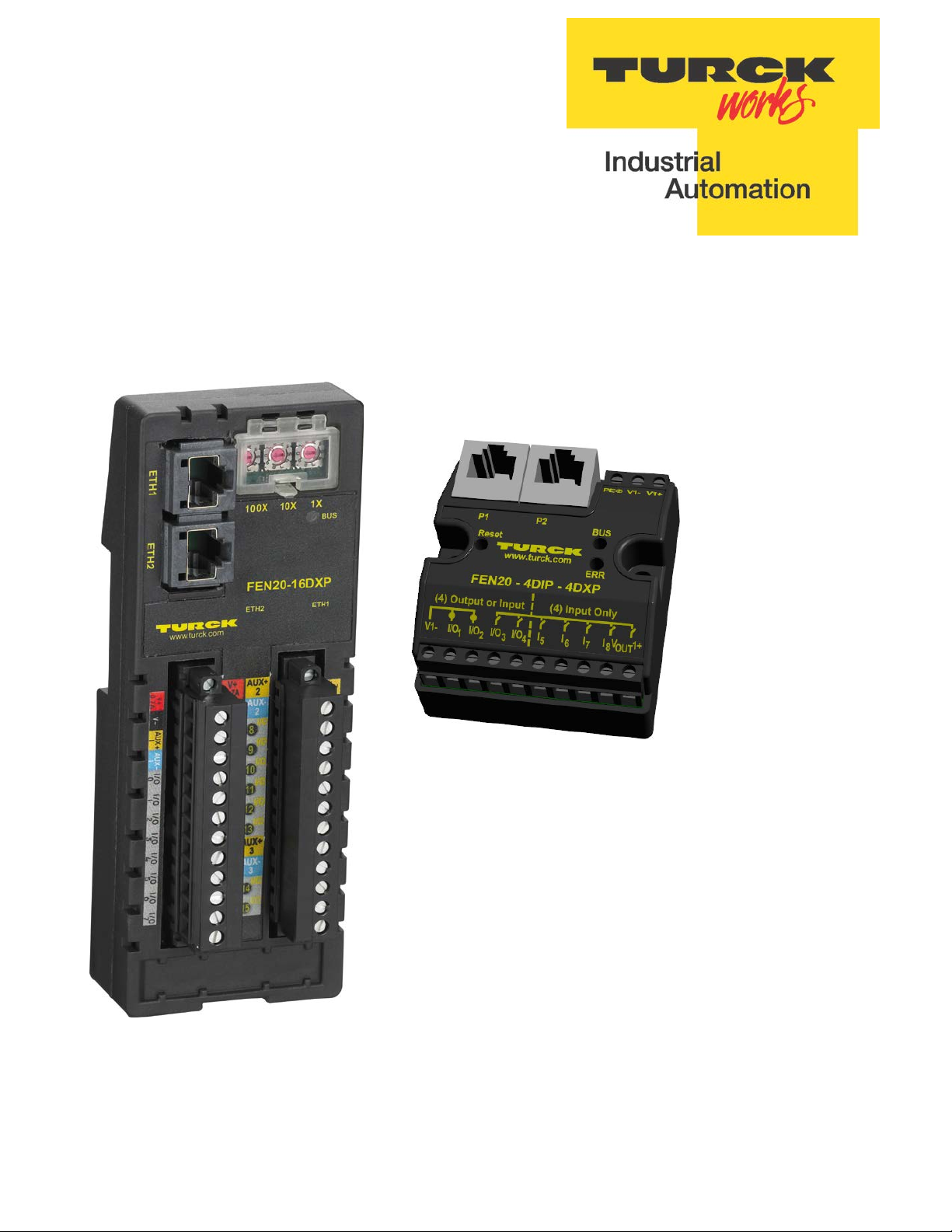
FEN20 Modules
Introduction
FEN20-16DXP is a multiprotocol communication adapter which supports following networking standards:
• EtherNet/IP
• PROFINET
• Modbus TCP/IP
The f actory default “ out of t he box” s etting i s t hat al l c ommunication pr otocols ar e e nabled. After po wer-up, a
multiprotocol device is listening on all necessary ports to detect on which kind of network it is used.
The “Active Fieldbus Protocol” is defined as the first protocol to do one of the following actions:
• EtherNet/IP: Establish a Class 1 Exclusive Owner connection to device.
• PROFINET RT: Connect request.
• Modbus TCP: Write to Output Register Range.
The Configuration Guide describes device features and configuration procedure in the EtherNet/IP
environment.
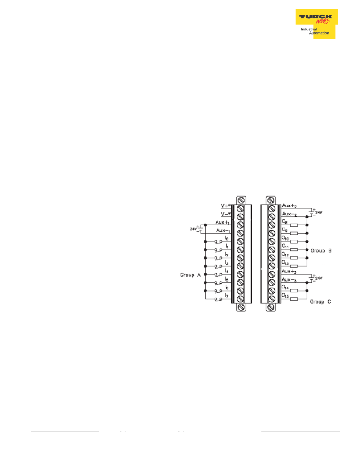
Connection Diagrams
FEN20-16DXP connection diagrams
• FEN20-16DXP wiring
• V1+ will have the following functions
• Station power and Group A of IOs
• Provide 700mA to Vaux1+
• It is galvanically isolated from groups B and C
• V2+ will have the following functions
• Power for Group B
• It is galvanically isolated from groups A and C
• V3+ will have the following functions
• Power for Group C
• It is galvanically isolated from groups A and B
4
Page 6

FEN20 Start-up Guide
LED Diagnostics
• LED Status
• I/O
IO0 – IO15
• BUS
• Solid Green: Active connection to master
• Flashing Green: Ready
• Solid Red: ACD or bit set in Status word
• Flashing Red: Blink/Wink command active
• Off: No power supplied
• ETH1/ETH2
• Solid Green: Ethernet Link (100 Mbps)
• Flashing Green: Ethernet communication (100 Mbps)
• Solid Yellow: Ethernet Link (10Mbps)
• Flashing Yellow: Ethernet communication (10 Mbps)
• Off: No Ethernet Link
• Solid Green: Input Responded, Output on
• Off: Input not asserted, output off
5
Page 7
FEN20-16DXP Configuration Assembly Data
Byte 0
Byte 2
Byte 4
Byte 6
Byte 8
Byte10-15
Reserved
FEN20 Start-up Guide
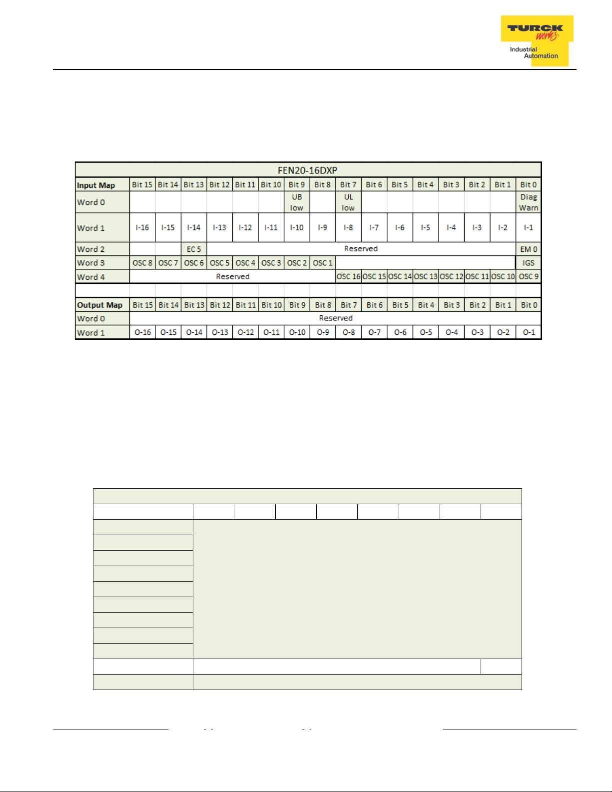
IO and Configuration Data Map
EtherNet/IP IO data map consists of:
• Produced (input) data: 5 x UINT (16-bit)
• Consumed (output) data: 2 x UINT (16-bit)
• Configuration data: 16 x USINT (8-bit)
Abbreviations:
• I1…I16: Input state
• O1…O16: Output state
• DiagWarn: Summarized diagnostic warning
• Ul: Ul voltage too low error
• Ub: Ub voltage too low error
• EM0: Summarized diagnostics mod 0
• IGS: Input group status error
• OSC1…16: Output status O1 – O16 short-circuit
• QC QuickConnect
Byte 1
Byte 3
Byte 5
Bit 7 Bit 6 Bit 5 Bit 4 Bit 3 Bit 2 Bit 1 Bit 0
Reserved
Byte 7
Byte 9 Reserved QC
6
Page 8
FEN20 Start-up Guide
Setting up the IP Address
The general procedure for IP address setup is:
• Set rotary switches to desired position
• Cycle (reset) power to the station
• Run IP address server to assign IP address
• Set address switches to rotary mode or PGM mode
• Cycle power to the station
When address switches are in rotary mode, the last octet may be dialed in 1-254 range.
Default IP Address
The default IP address is:
• IP-address 192.168.1.254
• Subnet mask 255.255.255.0
• Default gateway 192.168.1.1
To reset IP address to default, set address switches to 0 and reset device power.
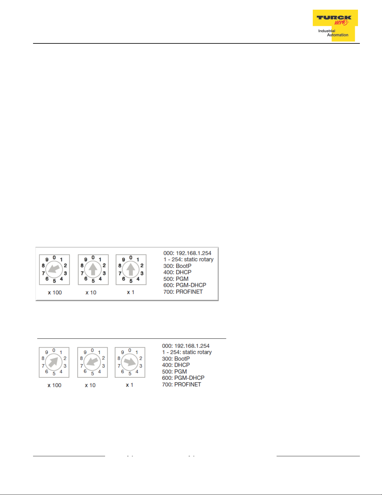
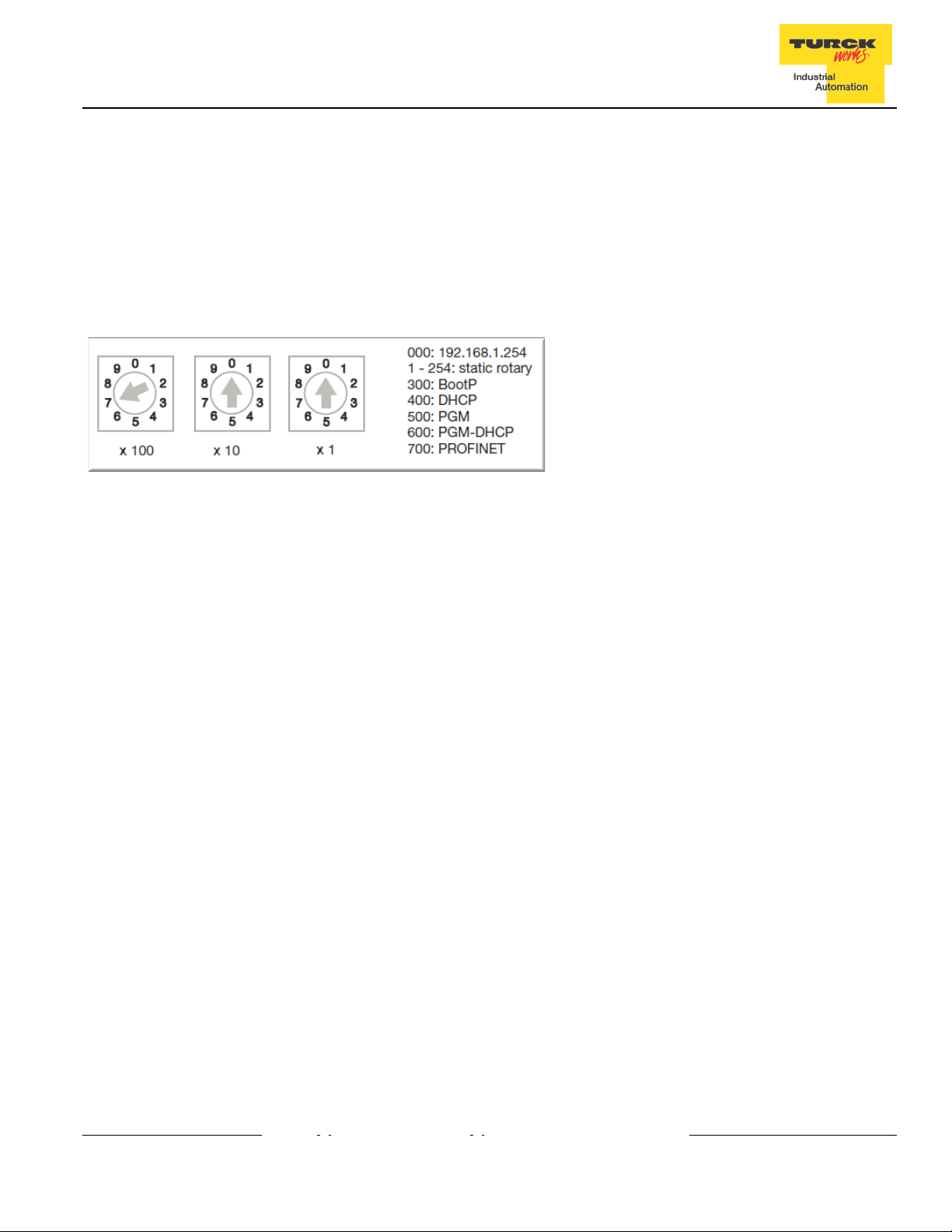
Address Switches
FEN20 devices have three rotary switches marked as follows:
x100 sets the last digit of IP address to a 100’s value
x10 sets the last digit of IP address to a 10’s value
x1 sets the last digit of IP address to a 1’s value
Switch position determines either address or device mode of operation as follows:
When using the static rotary mode, the last octet of the module’s IP address can be set via the rotary codingswitches on the module.
Address range is 1 to 254. Addresses 0 and 255 are reserved and cannot be used.
Following example shows the last octet set to of address xx.xxx.xxx.173
7
Page 9
FEN20 Start-up Guide
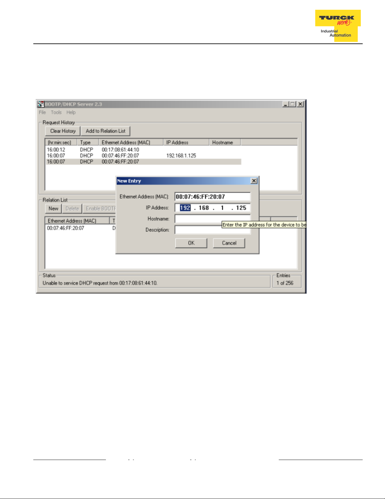
BOOTP/DHCP Mode (300/400)
An Ethernet station (client) may obtain IP address from the BOOTP / DHCP server when address switches are
set to 300 (BOOTP) or 400 (DHCP). The IP address, as well as the subnet mask assigned to the station, is
stored in the device’s EEPROM. When the station is subsequently switched to rotary or PGM-mode and power
rest, the IP address is read from the EEPROM.
8
Page 10
FEN20 Start-up Guide
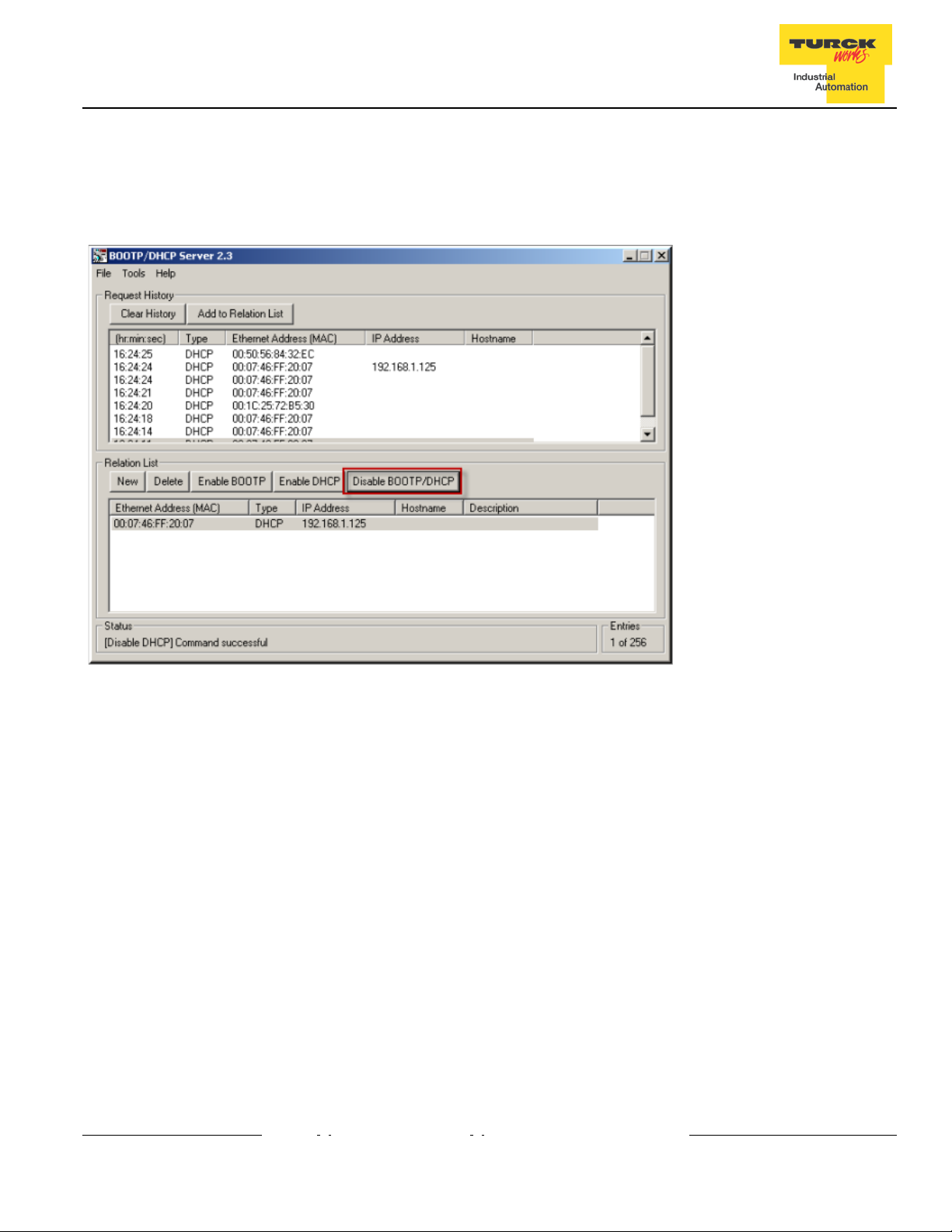
PGM-DHCP Mode (600)
When the rotary switches are set to 600 it enables PGM–DHCP mode of operation. This mode is the
Out-of-the-Box mode and provides the customer with powerful and convenient IP address setup. Procedure is
the identical as for DHCP mode. When finished, click on “Disable BOOTP/DHCP”. The device switches into
PGM mode and keeps assigned IP address in the EEPROM memory.
PGM Mode (500)
When the rotary switches are set to 500 (PGM mode), the device will use either the factory default IP address
on the first power-up or maintain current IP address whatever it is. Device IP address may be also changed,
when in PGM mode, with software tools like:
• Device WEB server
• TURCK IP address tool
• IOAssistant configuration tool
9
Page 11
FEN20 Start-up Guide
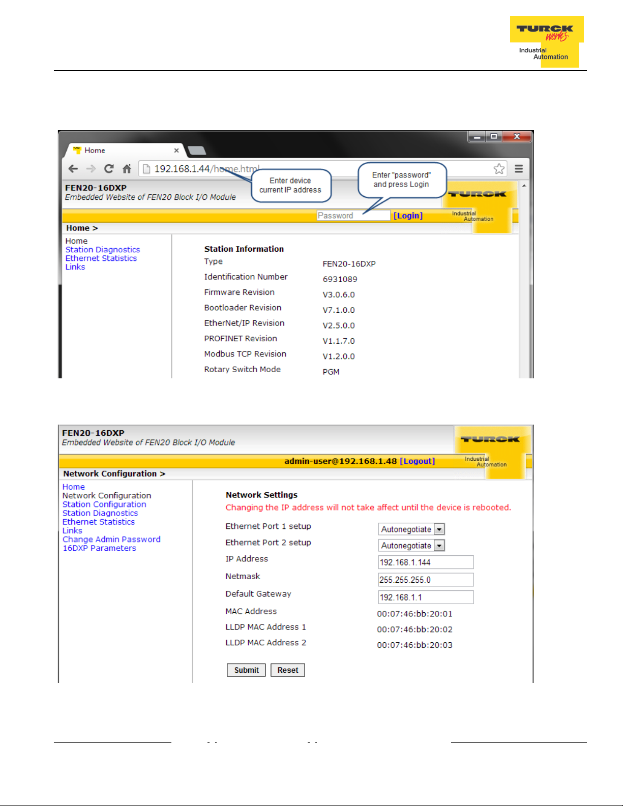
PGM and Web Server (500)
Use any web browser and enter current IP address of the device. When device web server starts, enter “password” into “Login” field:
Enter device new IP address, press “Submit” and then “Reset”. Restart web page.
10
Page 12
FEN20 Start-up Guide
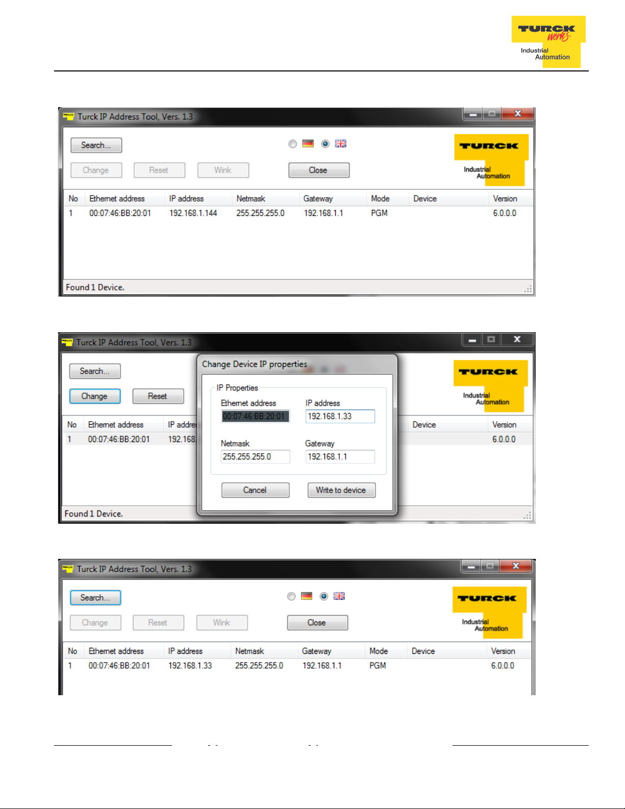
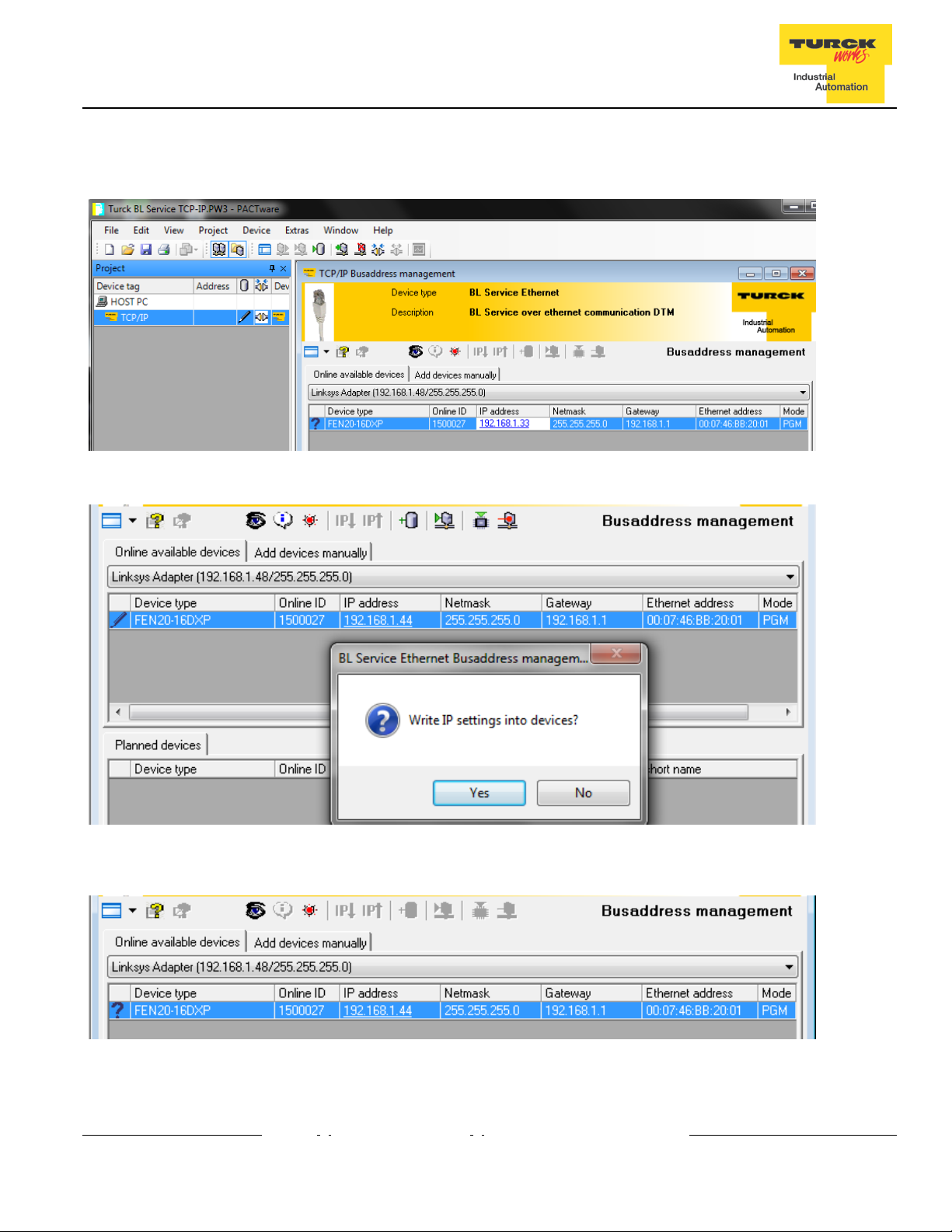
PGM and TURCK IP address tool (500)
Start the IP address tool and press search:
Highlight device, press “Change” button and enter new IP address; press “Write to device”.
Press search and verify address:
11
Page 13
FEN20 Start-up Guide
PGM and IOAssistant
Highlight currently displayed IP address and write new one. DO the same with Netmask and Gateway.
Press Apply and follow dialog:
New IP address is accepted:
12
Page 14
FEN20 Start-up Guide
RESTORE Mode (0)
The RESTORE mode is a special mode which restores the IP address to the factory default values. Station responds to PING command, but it does not operate when switches are set to 0.
Set all three rotary switches to 0 and cycle the power to the station. It instantaneously restores IP address, Mask
and Gateway as follows:
• IP address: 192.168.1.254
• Mask: 255.255.255.0
• Gateway: 192.168.1.1
Set rotary switches to any position as following diagram and cycle device power:
RECOVERY Mode (900)
The RECOVERY mode (900) is a special mode which resets all device resources to factory default
values. It will clear all previously assigned parameter values to the device. Set rotary switches to 900
and cycle the power to the device. Wait for a moment, set rotary switches as previously described and
cycle device power again.
13
Page 15

FEN20 Start-up Guide
EtherNet/IP Configuration
Following s ection pr ovides i nformation how to c onfigure F EN20 pr oduct line with R ockwell A utomation Logix
controllers (mainly ControlLogix, GuardLogix, CompactLogix controllers). Third party devices may be configured
using two different configuration methods which depend on a controller revision:
• Device configuration using EDS file ( Electronic Data Sheet):
All Log ix c ontrollers, r evision 20. 00.00 and above, s upport d evice c onfiguration us ing E DS f iles ( EDS
profiles) and configuration assembly data
• Device configuration using Ethernet Generic Profile:
All Logix controllers, revision 19.01.00 and below, support device configuration using Ethernet Generic
Device profile and Catalog files based on CIP bridging device concept
FEN20 Configuration using EDS Files
An EDS file which supports configuration assembly data can be imported into RSLogix5000 project as a third party
Add-on-Profile d evice. O nce i t i s imported, L ogix D esigner c reates d evice c onfiguration t ag t hat c ontains i ts
configuration data. It is saved in the project and it is pushed to the device whenever connection between the
controller and the device is established.
The FEN20 device configuration procedure includes following steps:
• Configure EtherNet/IP interface
• Create RSLogix5000 project
• Install device EDS file(s)
• FEN20 general configuration
• FEN20 connection configuration
• FEN20 input, output and configuration data tags
14
Page 16
FEN20 Start-up Guide
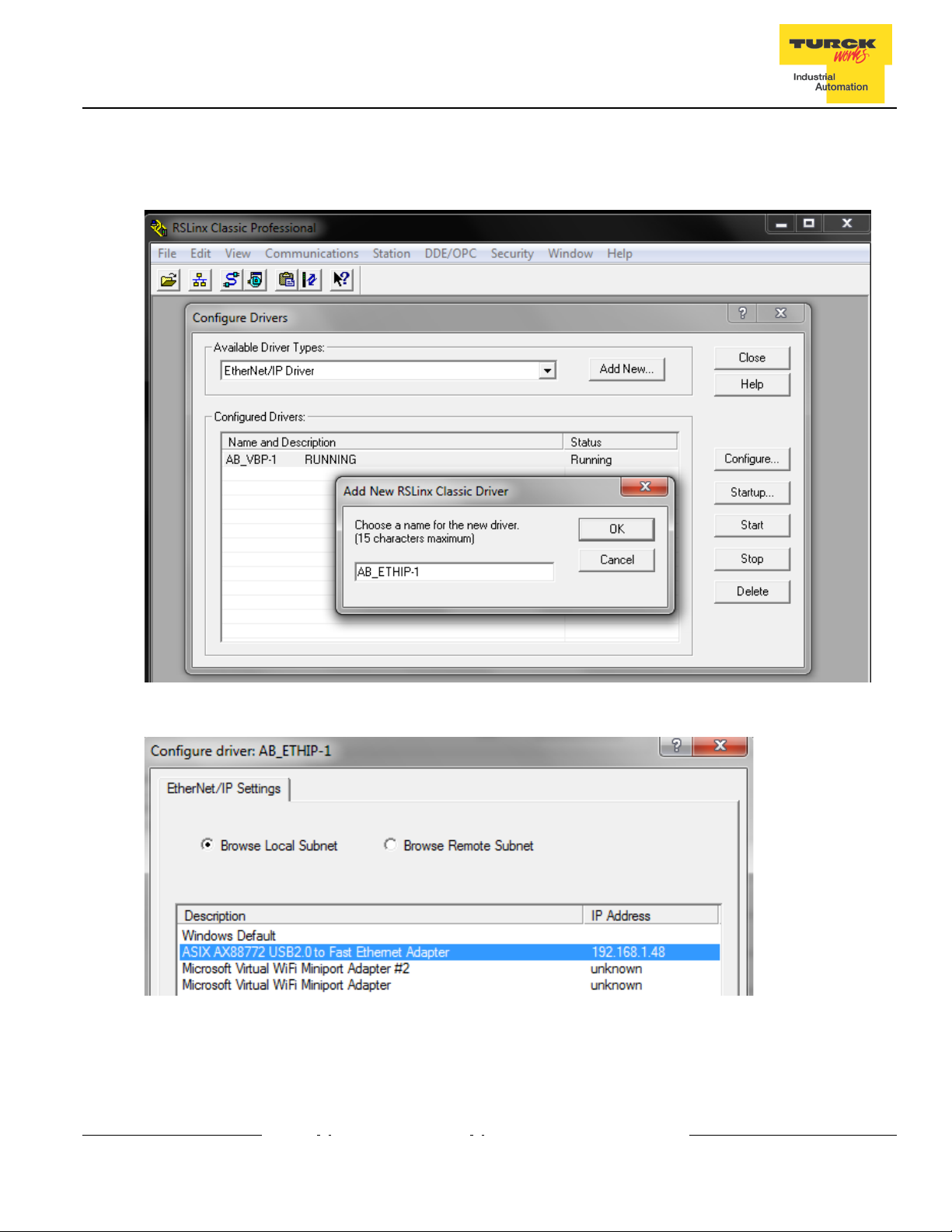
Configure User Interface
Configure user interface to the ControlLogix platform using RSLinx communication software and add
new EtherNet/IP driver. The assign IP address is actual address of the Ethernet port of the PC:
Select designated driver and click apply:
IP address 192.168.1.48 is address of a PC’s Ethernet port used for the network configuration.
15
Page 17
FEN20 Start-up Guide
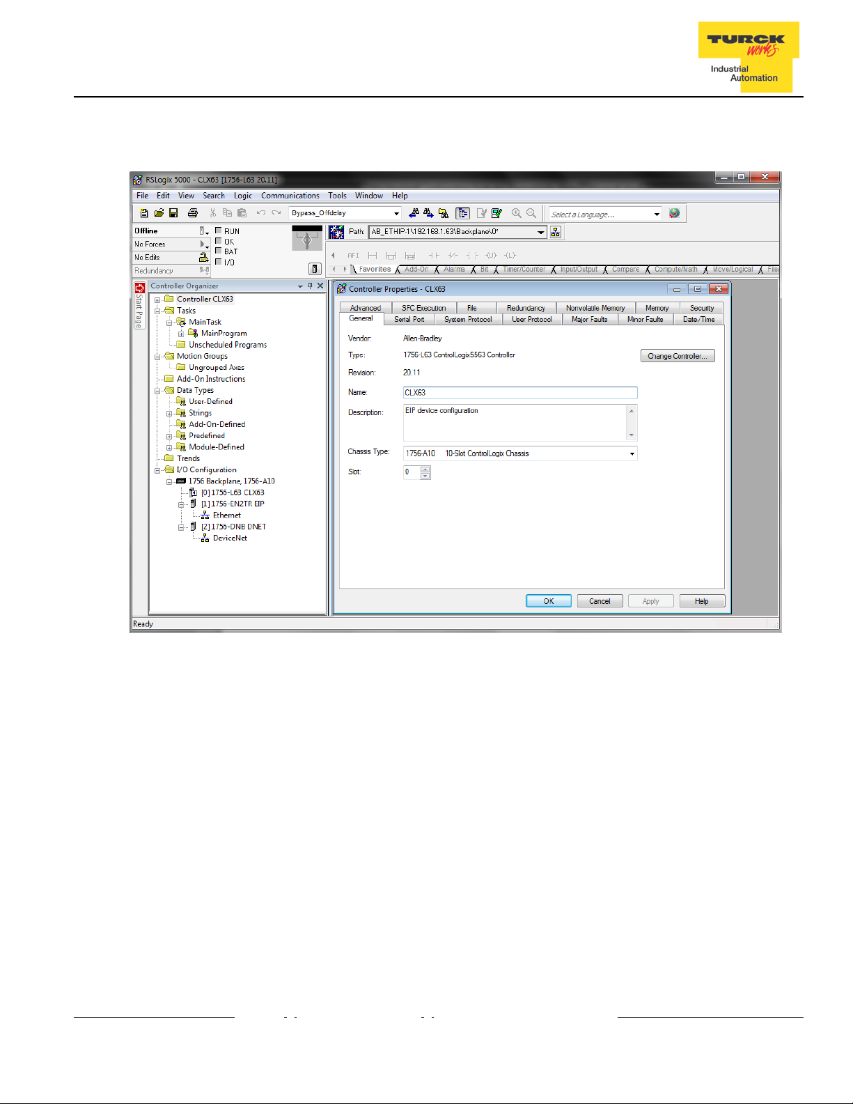
Create RSLogix5000 Project
Open new RSlogix5000 project and configure your PLC
16
Page 18
FEN20 Start-up Guide
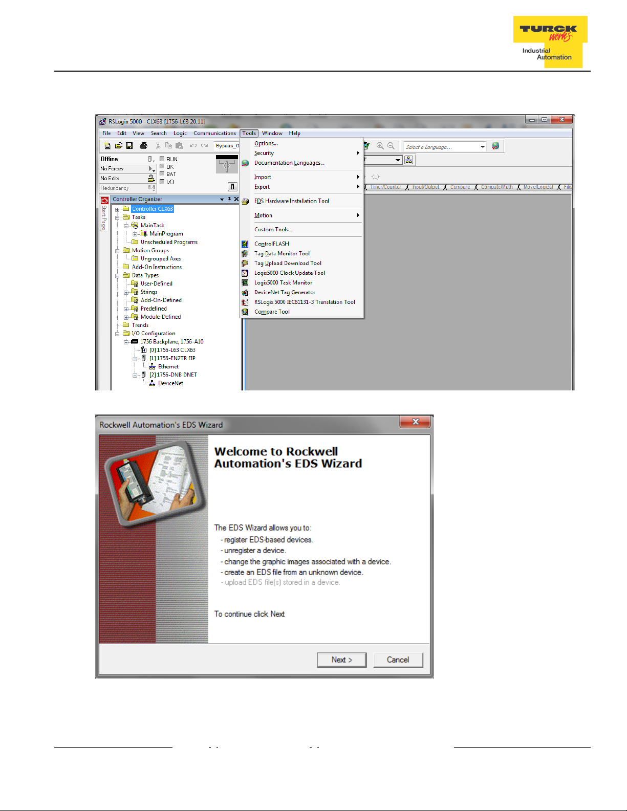
Install EDS Files
Tools > EDS Hardware Installation Tool
Follow istruction of the wizard
17
Page 19

FEN20 Start-up Guide
Register a single EDS file
Following file is registered:
18
Page 20

FEN20 Start-up Guide
Configure FEN20-16DXP
Following example shows how to add FEN20-16DXP device to the project. The same procedure is used
for any other FEN20 lwjerpq3rptq34ptoi module. To add new device to the EtherNet/IP network use:
File > New Component > Module
or right-click at “Ethernet” and select “New module”
19
Page 21

FEN20 Start-up Guide
New device may be located in the “Select Module Type” by scrolling:
By searching specific name:
20
Page 22

FEN20 Start-up Guide
Or by flitering the “Module Type Vendor Filters” to serch specific products, as follows:
If device name does not appear in the list of registered device, either device EDS file is not installed or
installation failed.
21
Page 23

FEN20 Start-up Guide
Enter required data into the “New Module” general page:
• Name (tag name) and description
• IP address
• Click “Change” to open Module Definition page
22
Page 24

FEN20 Start-up Guide
Module Definition Data Format
FEN20 supports INTEGER data format only. It is important to edit and change data format used by
RSLogix5000 to match INTEGER. A failure to do so may case erronious IO data or inoperable IO data update.
Use “Change” button to:
• Change data format to INTEGER
• Review connection type
FEN20 supports following connections:
• Exclusive Owner
• Input Only Connection
• Listen Only Connection
Note:
Exclusive Owner connection is the preferd, default, connection type use by the device. Input Only and Listen
Only connections are used to configure the device with multiple PLC’s and they do not support configuration
assemblies.
The “Module Definition” page provides following setup options:
The required setup for the FEN20:
23
Page 25

FEN20 Start-up Guide
Communication RPI, Multicast / Unicast
The “Connection” tab is used for selecting:
• RPI (Requested Packet Rate) is a scheduled interval when a Target (FEN20) and Origin (controller)
transmit data. The connection timeout may occure after 4xRPI time, when either Target or Origin
stops sending data.
• Unicast:
• Used for point-to-point communication (TCP, UDP)
• Both Producer /Consumer use IP address classes A, B, or C for data exchange
• No need to process and reject multicast packets
• Reduces burden on all EIP participants
• Multicast:
• Used for one-to-many communications (UDP)
• Multicast allows for multiple consumers. However, a single consumer is supported
• With multiple consumers, multicast is more timely efficient than unicast
• Uses IP address class D (multicast addresses, e.g. 239.192.1.2)
Following dialog to complete device configuration.
24
Page 26

FEN20 Start-up Guide
Input, Output and Configuration Data Tags
The new device, after being configured, is added to the Controller Oranizer and associated input, output
and configuration tags are created at the Controller Tags level.
Input data tag content:
Note: Device “ConnectionFaulted” flag is attached to the input data by the controller.
25
Page 27

FEN20 Start-up Guide
Output data tag content:
Configuration data tag content:
Note: The “Quick_Connect” parameter may be used only in conjuction with QC infrastructure and
program control. When enabled, it causes ethernet ports to be set as described in the FEN20 and QC
section of the document.
26
Page 28

FEN20 Start-up Guide
FEN20 Profile Info
The device property is a subject to change. It also provides path to check installed EDS file: right-click
on the device and select “Properties”:
Click on marked icon and follow instructions:
27
Page 29

FEN20 Start-up Guide
FEN20 Configured as Ethernet Generic Device
Earlier versions of RSlogix5000 Programming Software and Logix controllers, revision 19 or less do not
support EDS files. Third party devices are configured using Ethernet Generic profile. It generally creates
input, output and configuration tags as array of data. Configuration data is manually entered. A device is
implicitly configured using one of the following connections: Exclusive Owner (default), Input Only or
Listen Only connection.
The FEN20-16DXP device configuration procedure includes following steps:
• Create RSLogix5000 project
• Add new device
• Configure connection data
• Review input, output and configuration data tags
Create a New RSLogix5000 Project
28
Page 30

FEN20 Start-up Guide
Add New Device
Right click to add new module:
Select “ETHERNET-MODULE” and click “OK”:
New device configuration page looks as follows:
29
Page 31

Input
instance
Output
instance
Configuration
instance
FEN20-16DXP
103 5 104 2 106 0
FEN20 Start-up Guide
Enter following data and click OK:
• Name
• CommFormat field : Data – INT
• IP address
• Assembly instances and size per Table 2.1:
The device is implicitly configured with the controller using “Exclusive Owner” connection. It is defult
connection and only one that supports configuration assembly data.
Table 2.1 contains assembly instance and data size information for the FEN20 product family. The
configuration assembly data is pushed to the device during the communication startup (a Forward
Open request).
Exclusive Owner
connection
assembly
Input
size
assembly
Output
size
Exclusive Owner configuration data
Configure connection data according to the project requirements:
assembly
Configuration
size
Table 2.1
–
30
Page 32

Bit7
BIt6
Bit5
Bit4
Bit3
Bit2
Bit1
Bit0
Byte5
FEN20 Start-up Guide
Configuration Assembly Data
The device Configuration data is an array of data saves in a PLC. It pushes configuration to the device
during the Forward Open request. That occurs every time when device is connected, or power reset or
replaced with the same model.
Following table shows the structure of the FEN20-16DXP configuration data:
Byte0
Byte1
Byte2
Byte3
Byte4
Byte6
Byte7
Byte8
Byte9 Reserved QC
Byte10-15 Reserved
Table 2.4 – FEN20-16DXP configuration data
Abbreviations:
QC - Quick Connect
FEN20-16DXP
Reserved
31
Page 33

Input
instance
Output
instance
Configuration
instance
FEN20-16DXP
103 5 254
n/a
106
0
FEN20 Start-up Guide
Input Only Connection Configuration
Input Only connection is used to configure a device when:
• It is configured with multiple PLCs (max three) where only one is Ecxlusive Owner
• Other PLCs get input data only. They maintaine connection if exclusive owner is closed
• PLCs have to be set to the same RPI and must use MULTICAST messaging. PLCs may reside on
different subnets, VLANs, when infrastructure is available.
Enter following data and click OK:
• Name
• CommFormat field : Input Data – INT
• IP address
• Assembly instances and size per Table 2.2:
The device is implicitly configured with the controller using “Input Only” connection. Table 2.2 contains
assembly instance and data size information for the FEN20-L1 product family.
Input Only
connection
assembly
Input
size
assembly
Output
size
assembly
Configuration
size
Table 2.2
– Input
Only
configuration data
Note: If multiple connections to the device are used, then use casme RPI and Multicast
32
Page 34

Input
instance
Output
instance
Configuration
instance
FEN20-16DXP
103 5 255
n/a
106
0
FEN20 Start-up Guide
Listen Only Connection Configuration
Listen Only connection is used to configure a device when:
• It is configured with multiple PLCs (max three) where only one is Ecxlusive Owner
• Other PLCs get input data only. They drop connection if exclusive owner is closed
• PLCs have to be set to the same RPI and must use MULTICAST messaging. PLCs may reside on
different subnets, VLANs, when infrastructure is available.
Enter following data and click OK:
• Name
• CommFormat field : Input Data – INT
• IP address
• Assembly instances and size per Table 2.3:
Note: If multiple connections to the device are used, then use casme RPI and Multicast
The device is implicitly configured with the controller using “Input Only” connection. Table 2.3
contains assembly instance and data size information for the FEN20-L1 product family
Listen Only
connection
assembly
Input
size
assembly
Output
size
assembly
Configuration
size
Table 2.3
– Listen
Only
configuration data
33
Page 35

FEN20 Start-up Guide
FEN20 and DLR Network
A Device Level Ring (DLR) network is the EtherNet/IP network capable of fast recovery and uninterrupted
service in case of a single break point in network topology. It consists of a ring supervisor and ring nodes
connected in closed loop, ring topology. The ring supervisor maintains DLR protocol, performs fast fault
detection and reconfiguration of the network architecture into a linear in less than 3msec for 50 node network.
Nodes do not require any DLR related configuration and no external switches are necessary. Following image
illustrates a simple ring network:
FEN20 DLR features
FEN20 series is designed to meet DLR network requirements including:
• Compliance with the DLR and QoS Object Specification,
Volume 2: EtherNet/IP Adaptation of CIP, Chapter 5: Object library, Edition 1.15
• Integrated embedded switching technology that supports two external and an internal Ethernet ports
with following features:
• Auto-negotiation, with 10/100Mbps, full/half duplex
• Forced setting of speed/duplex
• Turn off flow control on ring ports;
• Auto MDIX (medium dependent interface crossover), in both auto-negotiate and forced
speed/duplex modes.
• Fault detection in the ring topology on either Ethernet port to the left or right of the breaking point
and error reporting to the supervisor
34
Page 36

Ports
Auto-negotiate
Port
Mode
Forced speed
/ duplex
Speed
Duplex
P1
Disabled
MDI
Enabled
100
Full
P2
Disabled
MDIX
Enabled
100
Full
FEN20 Start-up Guide
FEN20 and QC startup
The Quick Connect (QC) provides high device availability during startup of EtherNet/IP network.
Typical a pplication where it is i mplemented i s a f requent r obot tool ex change al ong as sembly lines i n t he
automotive industry, Figure 1.
Figure 1: Tool exchange
When new tool is engaged and locked into the robot arm, it generates a high lock signal to the Logix controller
which starts the QC allocation sequence. The QC sequence has to be complete in less than 350msec. The
QC is supported by Logix controller’s revision 20.00.00 and above.
The Quick Connect Sequence
Following sequence of events describe Quick Connect application:
• The Logix controller inhibits current QC modules and turns power OFF
• The robot arm physically disengages a tool
• The robot arm physically attaches a new tool that has one or more QC modules mounted on the tool
• The robot acknowledges successful attachment of a tool with appropriate lock signal
• The Logix controller turns power ON to the QC modules when lock signal is received
• The Logix controller waits for QC modules to complete initialization before it un-inhibits device
• The robot is ready for operation when connections with device are established
Ethernet port setup
FEN20 Ethernet ports are marked as:
• “P1”, Ethernet port 1
• “P2”, Ethernet port 2
Note that it is essential to connect incoming Ethernet cable to P1. When QC is enabled, Ethernet ports
are set as follows:
35
Page 37

FEN20 Start-up Guide
Enable QC
• If FEN20 is configured using EDS file, set QC parameter to 1:
• If FEN20 is configured as Ethernet Generic module, set “… C:Data[9]:= 1”
• Download configuration to the PLC and connect the gateway
• QC mode will be executed during the next gateway power-up and subsequent power cycles
Disable QC
• Clear QC attribute of the configuration assembly instance 106, byte 10
• Download configuration to the PLC and connect the gateway
• Standard mode is executed on the next and subsequent power cycles of the gateway
Reset to factory default
• Set the rotary switches to 900 and cycle power to the module
• Set the rotary switches to 100 and cycle power to the module
• The module is reset to factory default settings and
• IP address 192.168.1.100
• Mask 255.255.255.0
• Gateway 192.168.1.1
QC startup time
The startup time is 200msec.
36
Page 38

FEN20 Start-up Guide
PROFINET Configuration
Setup
GE Proficy Machine Edition Setup
It is assumed that there is working knowledge of GE Proficy Machine Edition. If not, please refer to the
GE Proficy Machine Edition Manual
Create a New project in Proficy using New Project Wizard or Open Project
File -> New Project
For a new project, insert the Project Name, Project Template, and Project location. When done click “OK”.
.
37
Page 39

FEN20 Start-up Guide
Once the project is in Proficy, Right click on the Processor and select the CPU . Click “OK”
To add the Profinet Controller, right click on the slot the Profinet card is in the chassis and in the pop up window
click Add Module
38
Page 40

FEN20 Start-up Guide
In the Catalog Window, click on the Bus Controller Tab and select communication master. In our example, the
RX3i Profibus Master and RX3i Profinet Controller are used. Click “OK”.
39
Page 41

FEN20 Start-up Guide
IP Addressing
In Turck products, the IP addressing can be set by either connecting to the Turck Gateway through Pactware,
the IP address tool, or through Internet Explorer or modifying the first three octets of the IP Address. The last
octet will be set by the rotary dials or dip switches.
• Right click on the Profinet Controller in the Navigator Window. Select Launch Discovery Tool in the
Pop up Window
• Click on Refresh Device List to bring list of devices on the network.
• Select device to be modified and click edit device.
40
Page 42

FEN20 Start-up Guide
• In the properties window, the Device Name and IP address can be changed. You can also reset the
device to factory defaults and identify the device on the network. When identifing the device, the
LEDs on the gateway will flash. When Done click on the exit button
41
Page 43

FEN20 Start-up Guide
Installing GSD / GSDML Files in the Hardware Configuration
In the Toolchest window click on the dropdown arrow and select a Profibus /Profinet Device.
Right mouse click on the Toolchest window, click Assistants -> Add GSD File…
42
Page 44

FEN20 Start-up Guide
• Browse to the folder where the GSD file is located.
• Select file(s). Click “Open”.
• Note: All files with .GSD are the default GSD files in the English language. Other versions may
include GSE (English), GSF (French), and GSG (German) languages.
• All Profinet files are .XML files.
43
Page 45

FEN20 Start-up Guide
Adding a Profinet Device onto the Network.
• Click on the Profinet Devices drop down in the Toolchest
• Click on the folder to open the folder
• Click on the GSDML file and drag it to the Profinet card.
44
Page 46

FEN20 Start-up Guide
• Once it is under the Profinet, click on the gateway and the device name and IP Address will be in the
Inspector. This must match the configuration downloaded to the gateway when using the network
discovery tool.
45
Page 47

FEN20 Start-up Guide
• Double click on turck-fen20=16dxp to bring up the properties / station parameters of the gateway.
Double click on slot 1 to bring parameters for the 16 DXP points
46
Page 48

FEN20 Start-up Guide
• This will bring up the GW parameters for Profinet.
• After changing the parameters click the X to close the window.
47
Page 49

FEN20 Start-up Guide
Modbus TCP Configuration
The following pages contain step by step instructions to set up communication between a Turck FEN20-16DXP
multriprotocol slave to a Turck VT250-57x-L7-IPM HMI display. This example will use Modbus TCP
communication between the devices.
Hardware
The following hardware was used to create this startup guide.
- VT250-57x-L7-IPM – Turck programmable HMI. (note: any VT250 model can be used following the same
steps)
- FEN20-16DXP – Multiprotocol 16 DI/DO slave
- SE-44X-E924 – 9 Port Unmanaged Ethernet Switch
- Ethernet cables
- 24 VDC Power supply
Software
The following software will be required to setup this system:
- CoDeSys V3.5 SP1 Hotfix 1 (can be downloaded from
http://pdb.turck.de/media/_en/Anlagen/SW_CoDeSys_v3510.zip)
- Turck IP address tool (can be downloaded from www.turck-usa.com/Support/Downloads_~_Software/
)
Setup
Hardware setup
1. Change the rotary switches on the FEN20 to 0,1,3 to have an IP address of 192.168.1.13
2. Connect VT250 and FEN20 to the Ethernet switch
3. Power up both devices
4. Setup the IP address on the VT250 using IP address tool:
48
Page 50

FEN20 Start-up Guide
Setting Up the VT250
1) File, new project
2) Select standard project and name it
49
Page 51

FEN20 Start-up Guide
3) Select Turck VT250-57x and click OK
4) Configure the communication with VT250 in Codesys. Go to Devices, double click on Device (VT25057x). Click on scan network to find the connected VT250
50
Page 52

FEN20 Start-up Guide
5) Click on the desired VT250 to highlight it and click on “Set active path”. The selection becomes bold
6) Right click on “Device (Turck VT250-57x)” and click on “Add device”
51
Page 53

FEN20 Start-up Guide
7) Select “Ethernet adapter” and click “Add device”
8) Right click on the recently added Ethernet adapter and click “Add device”
52
Page 54

FEN20 Start-up Guide
9) Select “Modbus TCP master netX” from the list and click “add device”
10) Right click on the recently added Modbus master, click on “Add device”
53
Page 55

FEN20 Start-up Guide
11) Select Modbus TCP slave
12) This will be the FEN20. Name can be changed by right clicking on it, and click properties
54
Page 56

FEN20 Start-up Guide
13) Change name
14) Double click on the Modbus slave to change its configuration. First we need to assign the IP address.
For this example we are using 192.168.1.13
55
Page 57

FEN20 Start-up Guide
15) The communication between Modbus TCP master and Modbus Slaves is realized via Modbus channels.
To configure them click on Modbus Slave Channel tab. The information for this channels is taken from
the Modbus TCP data map included on the datasheet
[Insert datasheet datamap]
16) Click on Modbus Slave Channel tab then add channel
17) First we will add the input data. This is using Read Holding Registers (Function Code 3). The offset is
the Modbus register indicated on the datamap. Length is the amount of registers (in WORD format). In
this case is offset is 0x000 and length 1
56
Page 58

FEN20 Start-up Guide
18) Same steps for the outputs. Add channel and use the information from the datamap. Write multiple
registers (Function code 16). Offset is 0x0800 and length is 1.
19) Once input and output channels are created, go to Modbus TCP Slave I/O mapping tab. We will assign
variable names for one input and one output bit (data tags). Make sure that “Always update variables” is
enabled
57
Page 59

FEN20 Start-up Guide
20) Double click on “PLC_PRG” on the devices tree. Create a small logic, when FEN20_INPUT0 is turn ON
activates FEN20_OUTPUT1.
21) Finally go to main menu “Online”. Click Login and Yes when prompted.
58
Page 60

FEN20 Start-up Guide
22) Put the VT250 on Run mode by clicking on Debug, Start
23) Connect an input to the first input of the FEN20 and turn it on. This will turn the second output on the
station.
59
 Loading...