

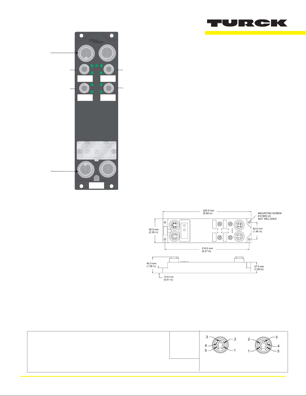
"T" Type
Aux Power
4 Aux
Powered
Outputs
(C4, C5)
2 DeviceNet
Powered
Inputs "2L"
Type (C0,
DeviceNet
C0
C1
C4
C5
FDNP-L0402H-TT-0198
This busstop® station is designed specifically to replace the
CDN-IOM-22-0032.
No reconfiguration of the PLC is necessary.
FDNP-L0402H-TT-0198
•
Advanced DeviceNet™ Station
•
2 x 2 discrete inputs and 2 discrete outputs
Applications
•
For wet or dry environments
•
For use with eight 3-wire or four 4-wire
proximity and photoelectric sensors, and
eight discrete actuators
Features
•
NPN/PNP short-circuit protected inputs with
open-circuit protection
•
2 Amp short-circuit protected outputs
•
Glass filled nylon with nickel plated brass
connectors
•
Rotary address switches
Connectors
DeviceNet
Style: 5-pin minifast®
Cordset: Bus Line use RSM RKM 579-*M
Tee: Bus Line use RSM 2RKM 57
Dimensions
1 = Shield
2 = V+
3 = V4 = CAN_H
5 = CAN_I
Male
Female
Through Bus
TURCK Inc. 10240290 Rev 1.2 02/06
TURCK
FDNP-L0402H-TT-0198
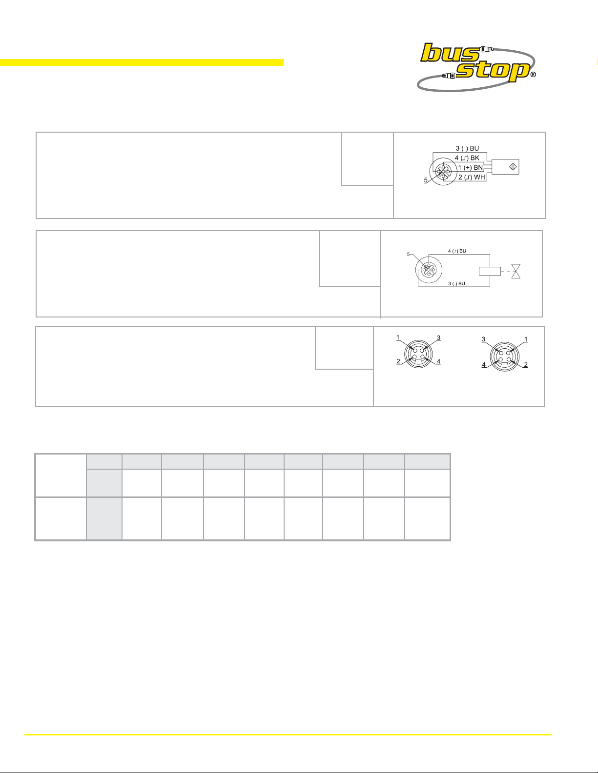
Connectors (continued)
Type "2L"
Style: 5-pin eurofast®
Cordset: Sensor with 2Signals use RK 4.4T-*-RS 4.4T
1 = V+ (A)
2 = Input B
3 = V4 = Input A
5 = V+ (B)
Splitter: Splitter and 2 Sensors VBRS 4.4-2RK 4T-*/*
Type "H"
Style: 5-pin eurofast®
Cordset: Single Output use RK 4.4T-*-RS 4.4T
Field Wireable: Single Output use BS 8141-0
Type "T"
Style: 4-pin minifast®
Cordset: Aux Power use RSM RKM 46-*M
Tee: Aux Power use RSM 2RKM 40
I/O Data Mapping
Product Code: 7/517 (205 hex)
Byte Bit 7 Bit 6 Bit 5 Bit 4 Bit 3 Bit 2 Bit 1 Bit 0
Input
Data
0 OSS-1 OSS-0 ISS-1 ISS-0 A-1 I-1 A-0 I-0
1 = N/C
2 = N/C
3 = GND
4 = Output
5 = PE
1 = Aux+
2 = E+
3 = E4 = Aux-
Sensor with 2 Signals
Single Output
Male
Auxiliary Power
Female
Output
0 - - - - - - O-1 O-0
Data
Abbreviations
I = Input Data (0=OFF, 1=ON)
A =
OSS-1 =
ISS-1 =
TURCK Inc. 10240290 Rev 1.2 02/06

TURCK
FDNP-L0402H-TT-0198
Module Specifications
Supply Voltage
Bus Power
Internal Current Consumption
Auxiliary Power
Input Circuits (4) NPN/PNP 3-wire sensors or dry contacts
Input Voltage (V+)
Open Circuit Current (V+)
Sensor Current (V+)
Input Signal Current (Input)
Input Delay
Maximum Switching Frequency
Output Circuits (2) DC actuators
Output Voltage
Output Load Current
Open Circuit Current
Maximum Switching Frequency
I/O LED Indications
11-26 VDC
≤100 mA plus sum of sensor currents (from bus power)
18-26 VDC, optically isolated
11-26 VDC (from bus power)
≤ 1mA
< 80 mA per input, short-circuit protected
OFF < 2 mA
ON 3.0-3.4 mA at 24 VDC
2.5 ms
100 Hz
18-26 VDC (from auxiliary power)
2.0 A per output (8 Amps total)
< 1 mA per output
100 Hz
Amber = Open circuit
OFF = Off
GREEN = On
RED = Short-circuit
Module Status LED
Green: working properly
Flashing Green: detecting autobaud rate
Flashing Red: I/O short-circuit
Network Status
Green: established connection
Flashing Green: ready for connection
Flashing Red: connection time-out
Red: connection not possible
Adjustments via Rotary Switch
Address
Communication Rate
Housing
Material
Enclosure
Operating Temperature
0-63
Auto/125k/250k/500k
Glass filled nylon with nickel plated brass connectors
NEMA 1, 3, 4, 12, 13 and IEC IP 67
-25° to 70°C (-13° to 158°F)
TURCK Inc. 10240290 Rev 1.2 02/06
 Loading...