

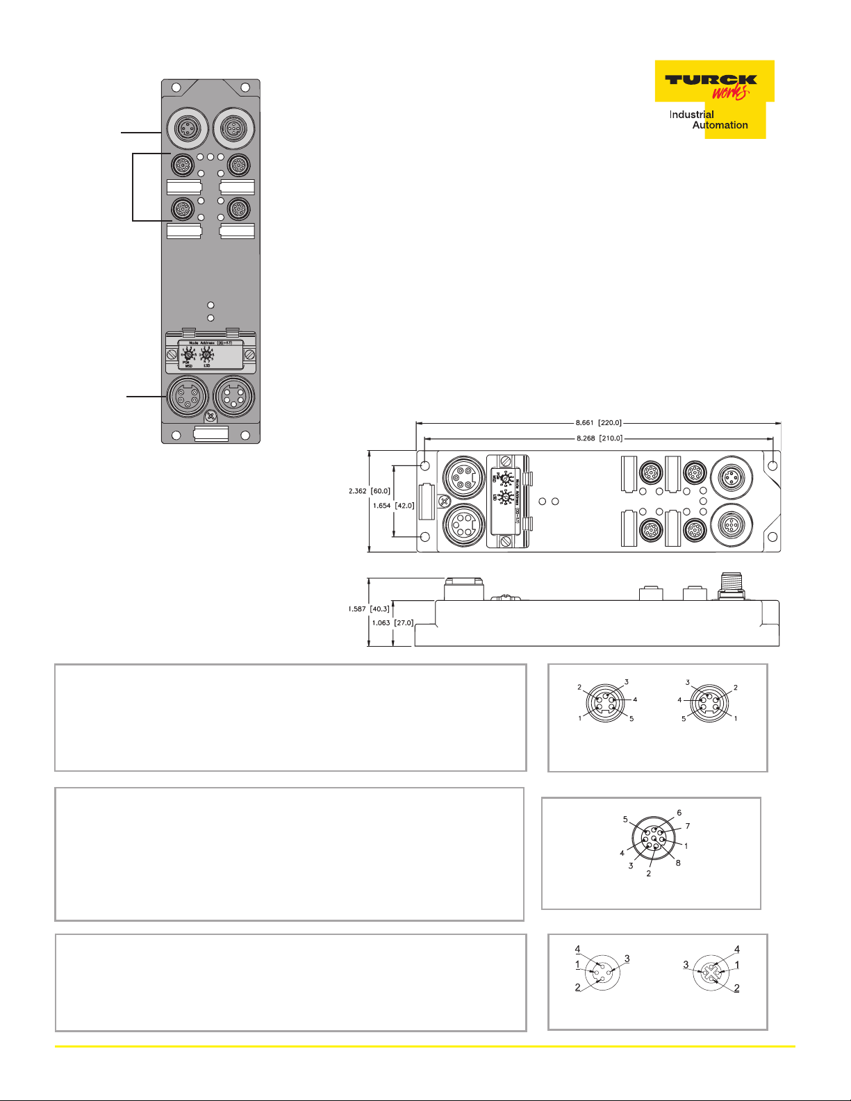
E1 and E2 Circuit
AUX Power
Safety Switch
DeviceNet
FDNP-ES44-TC
Thisstation is designed specifically for use with machine saftey switches. It
provides a convenient way to connect redundant circuits to the machine safety
switches using off the shelf cordsets. The station monitors the machine safety
switch state. The state of the switch is reported to the PLC via DeviceNet™.
The machine safety switches are connected via eight pin eurofast
®
connectors.
Four pins are required to provide redundant safety switch circuits. Two pins are
used to monitor the state of the machine safety switches. Two pins are used as an
output circuit. This output can be set by the PLC on DeviceNet.
The auxiliary power is connected via four pin eurofast connectors. Two of the
pins are used to provide external power for the station's input and output circuits.
Two of the pins are used to provide redundant safety switch circuits.
Dimensions
DeviceNet™
Style: 5-pin minifast
Cordset: Bus Line use RSM RKM 579-*M
Tee: Bus Line use RSM 2RKM 57
®
Safety Switch
Style: 8-pin eurofast
Cordset: Bus Line use RKC 8T-* RSC 8T
Jumper Module (for unused ports): RSC E80 DJ 45/67/28
®
Auxiliary Power: E1 and E2 Circuit
Style: 4-pin eurofast
Cordset: Bus Line use RKC 4.4T-* RSC 4.4T
®
1 = Shield
2 = V+
3 = V4 = CAN_H
5 = CAN_L
1 = IN
2 = OUT
3 = AUX (+)
4 = SC1
5 = SC1c
6 = SC2
7 = SC2c
8 = AUX (-)
1 = AUX (+)
2 = SC1
3 = SC2
4 = AUX (-)
MaleFemale
DeviceNet Connectors
Female
Male
Female
4 TURCK Inc. 10240371 Rev 1.3 1/09
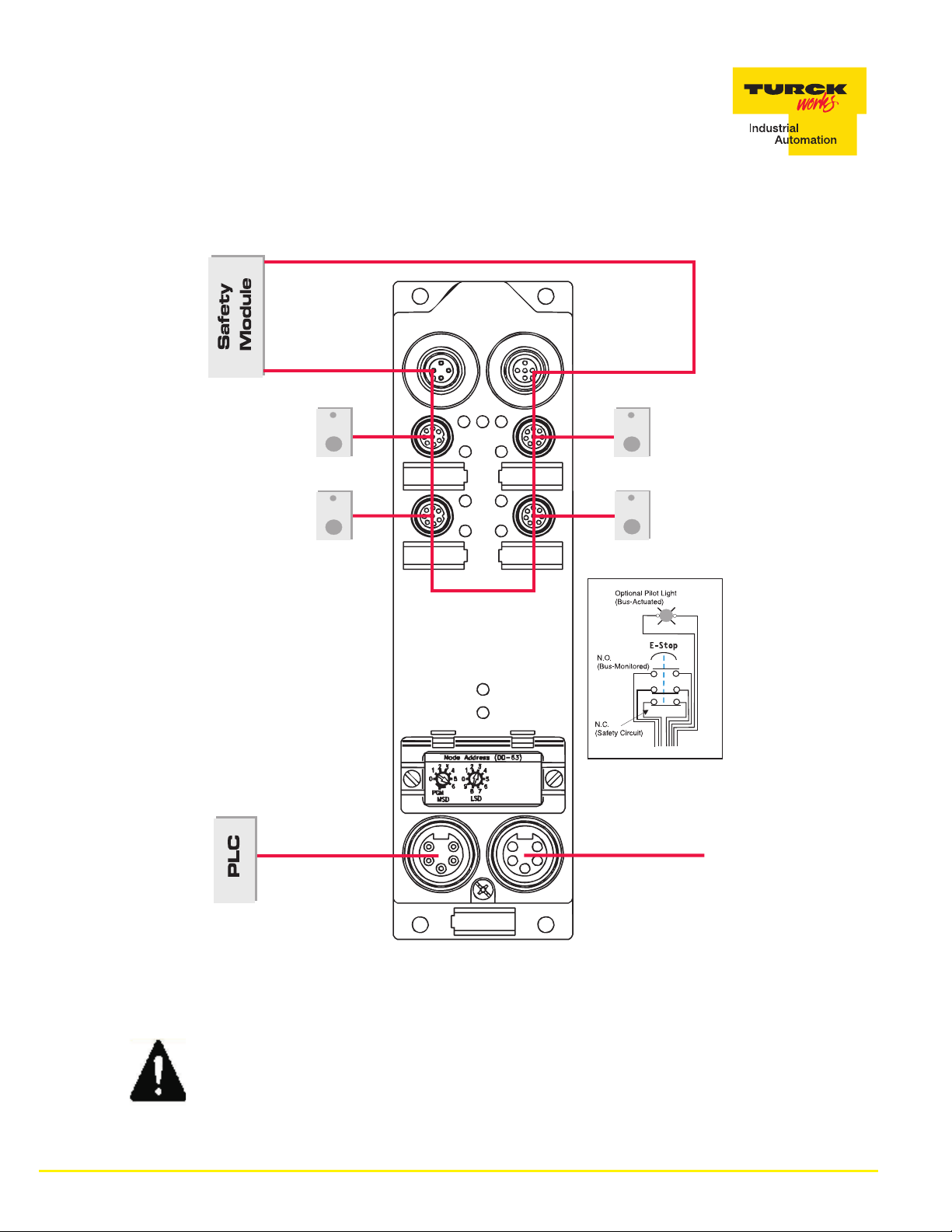
Wiring Configuration
WARNING!
To do so may create an unsafe situation, which could lead to serious injury or death.
5 TURCK Inc. 10240371 Rev 1.3 1/09
NEVER bypass or otherwise defeat the protective function of a safety switch.

Module Specifications
Supply Voltage
Bus Power
Internal Current Consumption
Auxiliary Power
Input Circuits
Input Voltage (V+)
Input Signal Current (Input)
Input Delay
Output Circuits
Output Voltage
Output Load Current
Maximum Switching Frequency
I/O LED Indications
Module Status LED
Network Status LED
11-26 VDC
≤40 mA
18-26 VDC
18-26 VDC auxiliary powered (optically isolated from bus)
OFF <2 mA
ON 3.0-3.4 mA at 24 VDC
2.5 ms
18-26 VDC auxiliary powered (optically isolated from bus)
0.5 A per output
100 Hz
OFF = Off
Green = On
Green: working properly
Flashing green: detecting autobaud rate
Flashing red: No Aux Connected
Green: established connection
Flashing Green: ready for connection
Flashing Red: connection time-out
Red: connection not possible
Adjustments
Address
Data Rate
Housing 168 x 97 x89 (H x W x D)
Material
Enclosure
Operating temperature
0-63 via Rotary Switch
Autobaud
Glass filled nylon with nickel plated brass connection
NEMA 1, 3, 4, 12, 13 and IEC IP 67
-25° to 70°C (-13° to 158°F)
I/O Data Mapping
Product Code: F1013
Input
Data
Output
Data
Byte Bit 7 Bit 6 Bit 5 Bit 4 Bit 3 Bit 2 Bit 1 Bit 0
0 APS - - - I-3 I-2 I-1 I-0
Byte Bit 7 Bit 6 Bit 5 Bit 4 Bit 3 Bit 2 Bit 1 Bit 0
0 - - - - O-3 O-2 O-1 O-0
Abbreviations
I = Input Data (0= OFF, 1= ON)
O = Output Data (0=OFF, 1=ON)
APS = AUX Power Status (0=OFF, 1=ON)
6 TURCK Inc. 10240371 Rev 1.3 1/09
 Loading...