

FDNL-XSG16-T
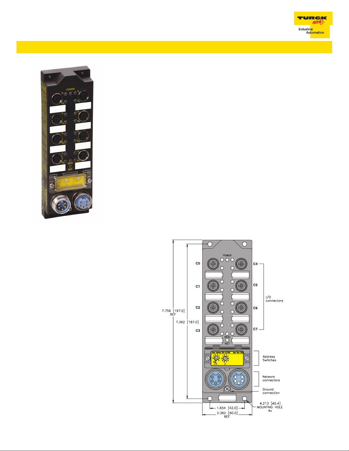
This station provides a connection for up to sixteen I/O points. There are two I/O points per
connector. Each connector can support two inputs or two outputs, or one input and one
output. This extremely flexible station can have any mixture of inputs and outputs.
To use an I/O point as an input, simply leave the corresponding output OFF. The I/O point
LED will turn green to indicate that the sensor is ON.
To use an I/O point as an output, simply turn on the corresponding output bit. The output
will switch high and the I/O LED will turn green. Note that this will in turn cause the
corresponding input bit to turn on. If the corresponding input does not turn on, the output
is shorted.
Because the inputs and outputs are powered off the same circuit, this station is not
recommended for E-stop outputs.
The node address can be set using the rotary switches located under the device cover or
through software node commissioning. The unit automatically detects the communication
rate.
The FDNL-XSG16-T supports explicit messaging, polled, change of state, and cyclic I/O
messages. These connections are established through UCMM or predefined master/ slave
connection set.
Recommended Cordsets:
Bus line: RSM RKM 579-*M
Inputs / Outputs: VBRS 4.4-2RK 4T-*/* or RK 4.4T-*-RS 4.4T
FDNL-XSG16-T
Extemely flexible DeviceNet™ station•
16 inputs or outputs•
Applications
For wet or dry environments•
For use with sixteen 3-wire •
proximity and photoelectric
sensors or 16 discrete actuators
Features
PNP short-circuit protected inputs•
0.5 amp short-circuit protected outputs•
Glass filled nylon with nickel •
plated brass connectors
Rotary address switches•
Dimensions
TURCK Inc. 10240485 Rev 1.1 9/08
FDNL-XSG16-T
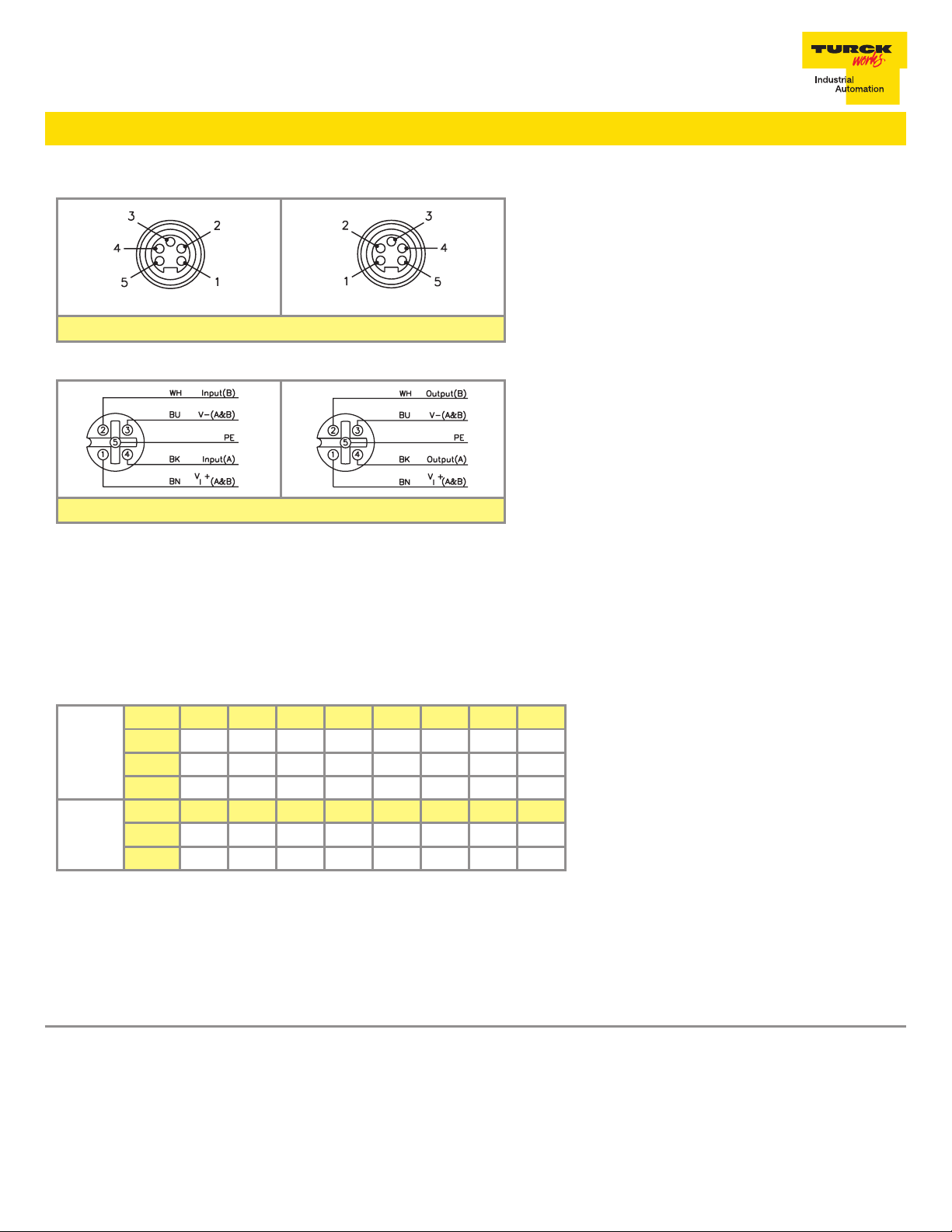
Connectors
5-pin Male 5-pin Female
Input / Output Connectors
DeviceNet™ minifast
1 = Shield
2 = V +
3 = V –
4 = CAN_H
5 = CAN_L
®
I/O Data Mapping
Item Number F2026
Product Type / Code: 7/2026
Byte Bit 7 Bit 6 Bit 5 Bit 4 Bit 3 Bit 2 Bit 1 Bit 0
Input
Data
Output
Data
0
1
2
Byte Bit 7 Bit 6 Bit 5 Bit 4 Bit 3 Bit 2 Bit 1 Bit 0
0
1
I-7 I-6 I-5 I-4 I-3 I-2 I-1 I-0
I-15 I-14 I-13 I-12 I-11 I-10 I-9 I-8
IGS OGS - - - - - -
O-7 O-6 O-5 O-4 O-3 O-2 O-1 O-0
O-15 O-14 O-13 O-12 O-11 O-10 O-9 O-8
Module Specifications
Supply Voltage
Bus Power 11-26 VDC
Internal Current Consumption <75 mA (from bus power)
Auxiliary Power 18-26 VDC
Abbreviations
I = Input Data (0=OFF, 1=ON)
IGS = Input Group Status (0=Working, 1=Fault)
O = OutputData (0=OFF, 1=ON)
OGS = Output Group Status (0=Working, 1=Fault)
TURCK Inc. 10240485 Rev 1.1 9/08
 Loading...