

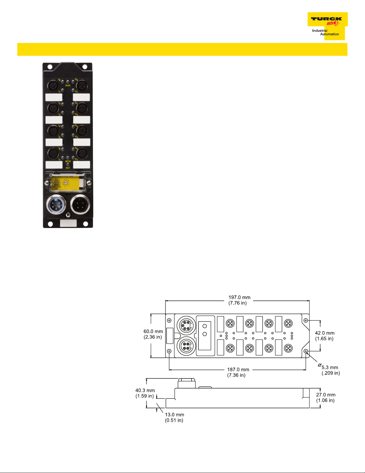
FDNL-S0808I-MM
This station provides eight inputs and eight outputs. There are four dual input connectors on the left
and four dual output connectors on the right. This unit is specically designed to work with electric
power and pin clamps. All inputs are powered by bus power. All outputs are powered by the auxiliary
power.
Each input connector provides V+, V-, Input A, and Input B. The V+ provides power to the attached
sensor. The V+ is short-circuit protected and monitored as a group. Input A is indicated by the upper
LED. Input B is indicated by the lower LED. A three-wire sensor will only use Input A, while a four-wire
sensor will use both.
Each output connector provides AUX+, AUX-, Output A, and Output B. Outputs are individually
short-circuit protected, but monitored as a group. Output A is indicated by the upper LED. Output B
is indicated by the lower LED. The AUX- is the output ground. The AUX+ line is short circuit protected
at 4Amps.
The node address can be set using the rotary switches located under the device cover or through
software node commissioning. The unit automatically detects the communication rate.
The FDNL-S0808I-MM supports explicit messaging, poll, change of state, and cyclic I/O messages.
These connections are established through UCMM or predened master/slave connection set.
Recommended Cordsets:
Bus Line: RSM RKM 579-*M
Auxiliary Power: RSM RKM 47-*M
Inputs / Outputs: VB2-RS 4.4T-*/2 RK 4.4T-*/* or RK 4.4T-*-RS 4.4T
Bus Tee: RSM 2RKM 57/C1125
Auxiliary Power Tee: RSM 2RKM 40
Combiner (Power Clamp): VB2-BKM 8*12RSG-0.2/0.2/CS10826
FDNL-S0808I-MM
• Advanced DeviceNet™ Station
• 4 x 2 discrete inputs and
4 x 2 discrete outputs
Applications
• For wet or dry environments
• For use with eight 3-wire or four
4-wire proximity and photoelectric
sensors, and eight discrete actuators
Features
• PNP short-circuit protected inputs
and open-circuit protection
• 2 Amp short-circuit protected outputs
• Glass lled nylon with nickel
plated brass connectors
• Rotary address switches
• 4 amp aux power available
on each output port
Dimensions
TURCK Inc. 10240325 Rev 1.7 07/11
FDNL-S0808I-MM
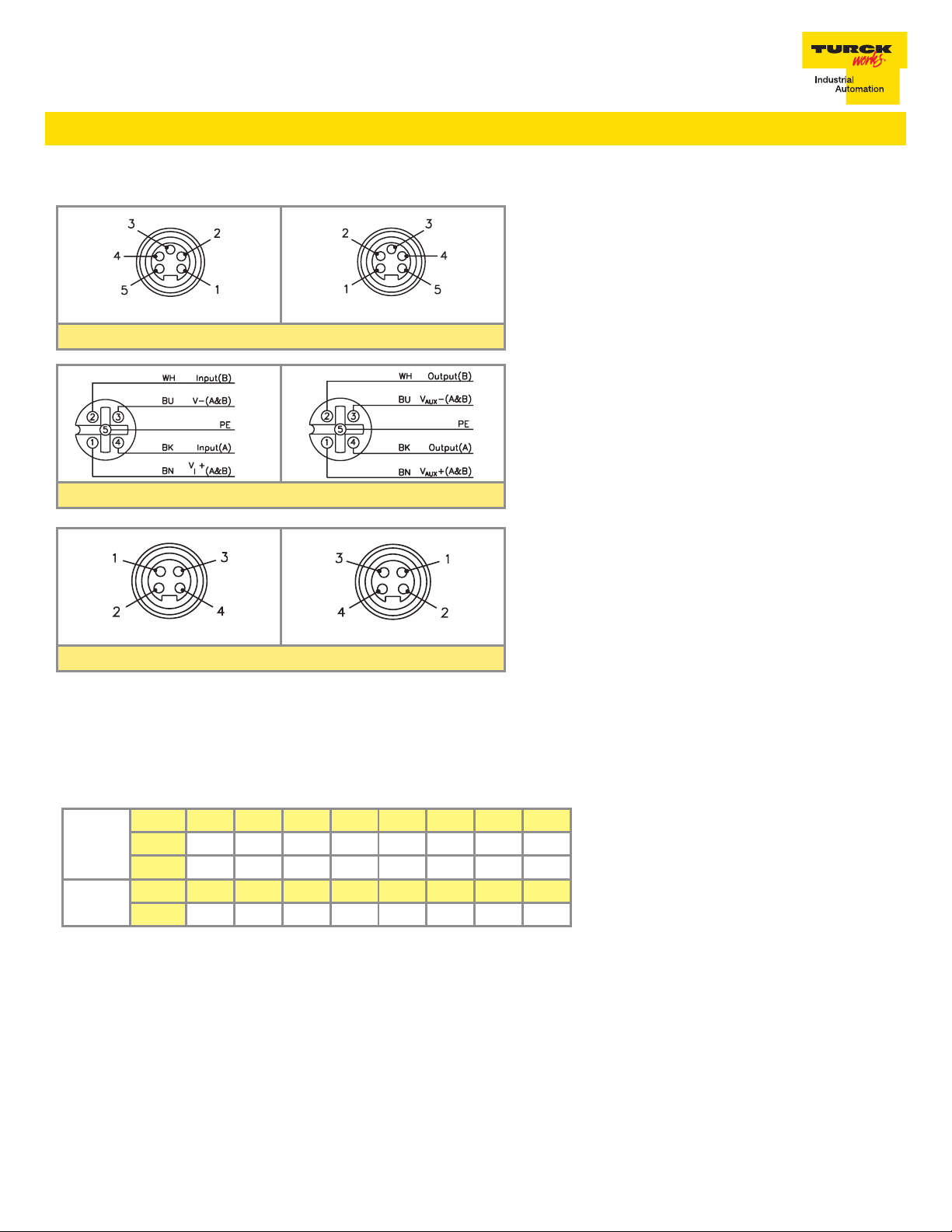
Connectors
5-pin Male 5-pin Female
Input / Output Connector
DeviceNet™ minifast
1 = Shield
2 = V +
3 = V –
4 = CAN_H
5 = CAN_L
®
1 = V
+
aux
2 = Pass thru
3 = Pass thru
4 = V
-
aux
4-pin Male 4-pin Female
Auxiliary Power
I/O Data Mapping
Item Number: F0188
Product Type/Code: 7/3009 (BC1 hex)
Byte Bit 7 Bit 6 Bit 5 Bit 4 Bit 3 Bit 2 Bit 1 Bit 0
Input
Data
Output
Data
0 I-7 I-6 I-5 I-4 I-3 I-2 I-1 I-0
1 IGS OGS - - - - - -
Byte Bit 7 Bit 6 Bit 5 Bit 4 Bit 3 Bit 2 Bit 1 Bit 0
0 O-7 O-6 O-5 O-4 O-3 O-2 O-1 O-0
Abbreviations
I = Input Data (0=OFF, 1=ON)
O = Output Data (0=OFF, 1=ON)
OGS = Output Group Status (0=Working, 1=Fault)
IGS = Input Group Status (0=Working, 1=Fault)
TURCK Inc. 10240325 Rev 1.7 07/11

FDNL-S0808I-MM
Module Specications
Supply Voltage
Bus Power 11-26 VDC
Internal Current Consumption ≤75 mA (plus the sum of inputs, from bus power)
Auxiliary Power 18-26 VDC, optically isolated, powers outputs
Input Circuits
Input Voltage 11-26 VDC (from bus power)
Input Short-Circuit 700 mA
Input Signal Current OFF <2 mA
ON 3.0-3.4 mA at 24 VDC
Input Delay 2.5 ms
Output Circuits
Output Voltage 18-26 VDC (from auxiliary power)
Output Load Current 2 A (9 A max)
Maximum Switching Frequency 100 Hz
I/O LED Indications
O = Not Active
Green = Active
4x2 Input DC / 4x2 Output DC
Module Status LED
O = Power O
Green =Operating
Flashing Green = Autobaud
Flashing Red = I/O Short-Circuit
Network Status LED
O = No Connection
Green = Established Connection
Flashing Green = Ready For Connection
Flashing Red = Connection Time-Out
Red = Connection Not Possible
Auxiliary Power Status LED
O = Power O
Green = Power On
Adjustments
Address 0-63 via Rotary Switch
Housing 197 x 60 x 40 (H x W x D)
Material Glass lled nylon with nickel plated brass connectors
Enclosure NEMA 1, 3, 4, 6, 6P, 12, 13, and IEC IP 67, 68, and 69K
Operating Temperature -40° to 70°C (-40° to 158° F)
TURCK Inc. 10240325 Rev 1.7 07/11
 Loading...