

Turck FDNL-L1600-T-V Data Sheet
16 Inputs
“2L” Type
(C0-C7)
C0-
C1-
C2-
C3-
-C4
-C5
-C6
-C7
This busstop
®
station takes in up to sixteen discrete three-wire inputs or eight
discrete four-wire input points per node. There are two inputs per connectorone on pin four and one on pin two. Each input automatically detects a
sourcing (PNP) or sinking (NPN) open-collector signal. Any combination of
NPN and PNP devices may be used.
Each input produces six bits of data- two input state bits, two short-circuit
status bits and two open-circuit status bits. The state bit is set when the
discrete input device closes. The LED at each input point indicates its status.
Each input pair is monitored for short-circuits and open circuits. Open circuit
detection is enabled using a software configuration tool. The status bits
automatically reset when the fault is removed.
Slave Address (0-99)
500
AUTO
2
2
3
3
4
4
250
1
1
5
5
0
0
125
9
6
9
6
PGM
8
8
7
7
x10 x1
DeviceNet
FDNL-L1600-T-V
•
Advanced DeviceNet™ Station
• 8 x 2 discrete inputs
Applications
• For high density applications
• For use with eight four-wire sensors
or sixteen three-wire sensors through
input splitters
Features
• PNP/NPN short-circuit protected
inputs with open-circuit protection
• Glass filled nylon housing with
stainless steel connectors
• Rotary Address Switches
The node address and communication rate can be set by the rotary switches
located under the device cover or through software node commissioning. The
unit automatically detects the communication rate.
The FDNL-L1600-T-V supports explicit messaging, poll, change of state, and
cyclic I/O messages. These connections are established through UCMM or
predefined master/slave connection set.
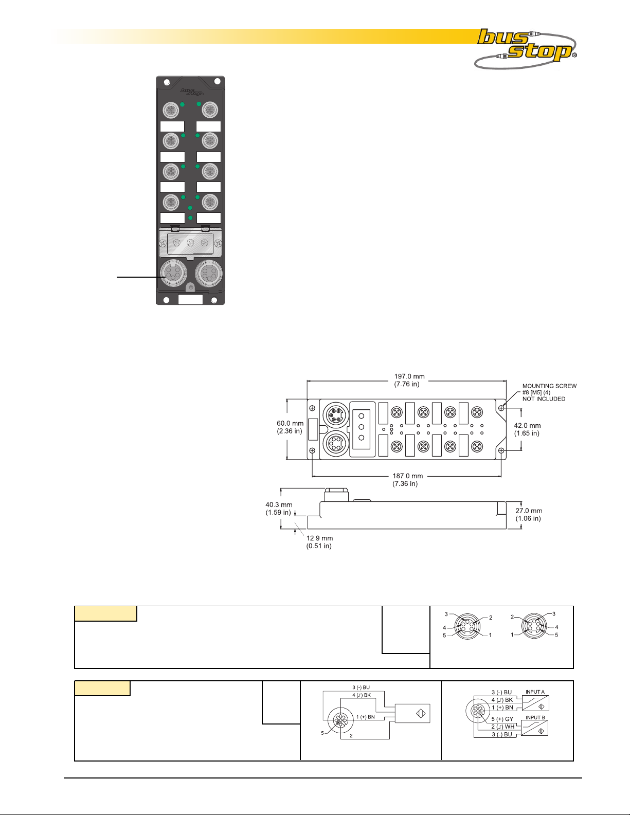
Dimensions
Connectors
DeviceNet
®®
®
Style: 5-Pin Style: 5-Pin
Style: 5-Pin
Style: 5-Pin Style: 5-Pin
CorCor
dset: Bus Line use RSM RKM 579- *Mdset: Bus Line use RSM RKM 579- *M
Cor
dset: Bus Line use RSM RKM 579- *M
CorCor
dset: Bus Line use RSM RKM 579- *Mdset: Bus Line use RSM RKM 579- *M
TT
ee : Bus Line use RSM 2RKM 57ee : Bus Line use RSM 2RKM 57
T
ee : Bus Line use RSM 2RKM 57
TT
ee : Bus Line use RSM 2RKM 57ee : Bus Line use RSM 2RKM 57
minifastminifast
minifast
minifastminifast
Type “2L”
CorCor
dset: Sensor with 2 Signals usedset: Sensor with 2 Signals use
Cor
dset: Sensor with 2 Signals use
CorCor
dset: Sensor with 2 Signals usedset: Sensor with 2 Signals use
RK 4.4TRK 4.4T
RK 4.4T
RK 4.4TRK 4.4T
Splitter: Splitter and 2 SensorsSplitter: Splitter and 2 Sensors
Splitter: Splitter and 2 Sensors
Splitter: Splitter and 2 SensorsSplitter: Splitter and 2 Sensors
use VBRS 4.5-2RK 4Tuse VBRS 4.5-2RK 4T
use VBRS 4.5-2RK 4T
use VBRS 4.5-2RK 4Tuse VBRS 4.5-2RK 4T
InterlinkBT® www.interlinkbt.com 10240323 Rev. 1.1 07/04
-*-RS 4.4T-*-RS 4.4T
-*-RS 4.4T
-*-RS 4.4T-*-RS 4.4T
®®
-*/*/S818-*/*/S818
-*/*/S818
-*/*/S818-*/*/S818
1= V +(A)
2 = Input B
3 = V 4 = Input A
5 = V +(B)
Sensor with 2 Signals
1 = Shield
2 = V +
3 = V 4 = CAN_H
5 = CAN_L
Male
Female
Through Bus
Splitter and 2 Sensors
1

Module Specifications
FDNL-L1600-T
16 NPN/PNP Input,
Per Point Diagnostic
Supply VSupply V
Supply V
Supply VSupply V
oltageoltage
oltage
oltageoltage
Bus power 11-26 VDC
Internal current consumption 140 mA plus sum of sensor currents (from bus power)
Input CirInput Cir
Input Cir
Input CirInput Cir
cuitscuits
cuits (16) PNP or NPN 3-wire sensors or dry contacts
cuitscuits
Input voltage (V+) 11-26 VDC (from bus power)
Open circuit current (V+) < 1mA
Sensor current (V+) <80 mA per input, short-circuit protected
Input signal current (Input) OFF <2mA
ON 3.0-3.4 mA at 24VDC
Maximum switching frequency 100 Hz
I/O LED IndicationsI/O LED Indications
I/O LED Indications
I/O LED IndicationsI/O LED Indications
Amber=Open-circuit
Off=Off
Green=On
Red=Short-circuit
Module Status LEDModule Status LED
Module Status LED
Module Status LEDModule Status LED
Green: working properly
Flashing green: detecting autobaud rate
Flashing red: I/O short-circuit
Network Status LEDNetwork Status LED
Network Status LED
Network Status LEDNetwork Status LED
Green: established connection
Flashing Green: ready for connection
Flashing red: connection time-out
Red: connection not possible
AdjustmentsAdjustments
Adjustments via Rotary Switch
AdjustmentsAdjustments
Address 0-63
Communication Rate Auto/125k/250k/500k
HousingHousing
Housing
HousingHousing
Material glass filled nylon with stainless steel connectors
Enclosure NEMA 1,3,4,12,13 and IEC IP 67
Operating temperature -25° to 70°C (-13° to 158°F)
I/O Data MappingI/O Data Mapping
I/O Data Mapping
I/O Data MappingI/O Data Mapping
Byte Bit 7 Bit 4Bit 5Bit 6 Bit 0Bit 1Bit 2Bit 3
I-5I-7 I-3I-4 I-1I-2 I-0I-6
I-12I-13I-14I-15 I-8I-9I-10I-11
IOS-4
Input
Data
0
1
2
ISS-7 ISS-6 ISS-1 ISS-0ISS-2ISS-3ISS-4ISS-5
3
4
5
ISS-14ISS-15 ISS-13 ISS-12 ISS-11 ISS-10 ISS-9 ISS-8
IOS-6
IOS-7 IOS-1IOS-2IOS-3IOS-5 IOS-0
IOS-14 IOS-13 IOS-12 IOS-11 IOS-10 IOS-9 IOS-8IOS-15
Abbreviations
I = Input Data (0=OFF, 1=ON) O = Output Data (0=OFF, 1=ON)
ISS = Input Short Status (0=Working, 1=Fault) OS = Output Status (0=Working, 1=Fault)
IOS = Input Open Status (0=Working, 1=Fault) OGS = Output Group Status (0=Working, 1=Fault)
IGS = Input Group Status (0=Working, 1=Fault) APS = Aux Power Status (0=OFF, 1=ON)
InterlinkBT® www.interlinkbt.com 10240323 Rev. 1.1 07/04
2
 Loading...