

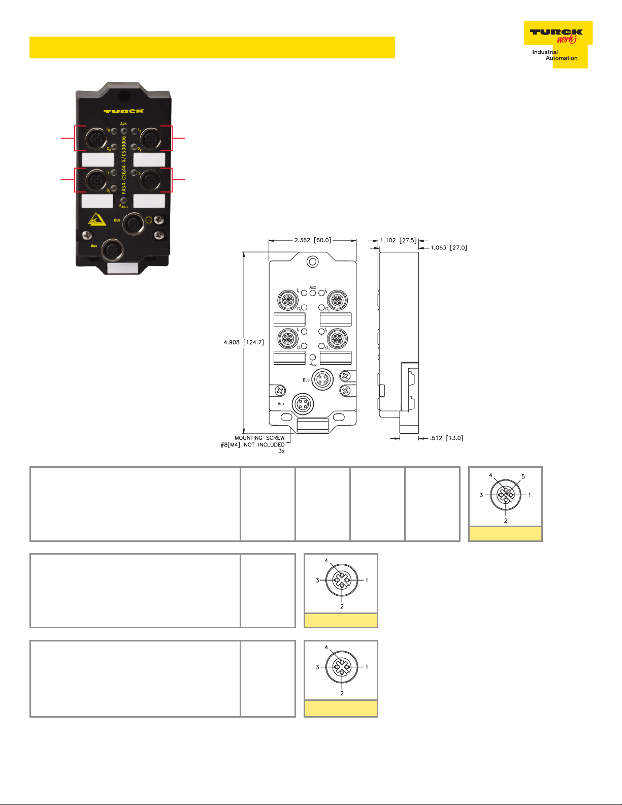
FAS4-CSG44-A/CS30006
J0
J1
Integrated Design
• AS-interface station
• Four input connectors
Applications
• For wet and dry environments
• For use with four 3-wire discrete
sensors
J2
J3
This module provides four connectors with four PNP inputs and four PNP outputs each
for connection to AS-interface
®
. The wiring is simple for a combined I/O device, such as
a Parts Verciation Array, or a splitter can be used for separate input and output devices.
A short-circuit on any output point is indicated by a fault signal per the AS-i V2.1
specication. All inputs are powered from the auxillary power supply. All outputs are
powered from the auxillary power. The station is fully encapsulated and potted and is
intended for use directly on a machine with no need for a separate enclosure.
This module supports both round cable (via a eurofast
®
connector) and AS-i standard
at cable. This station supports single addresses (1 to 31).
Dimensions
Features
• Gas lled nylon with nickel
plated brass connectors
Type “I/O”
Style: 5-pin eurofast
Cordset: Single Sensor use RK 4.4T-*-RS 4.4T
Field Wireable: Single Sensor use BS 8141-0
Type “Bus”
Style: 4-pin eurofast
Cordset: Bus Line use RSC 254-*M
Field Wireable: Bus Line use RKC 2RSC-25
* Also supports standard at AS-i cable
Type “Auxiliary”
Style: 4-pin eurofast
Cordset: Use RSC 254BK-*M (Right Angle: WSC
254BK-*M/C1251)
Field Wireable: Use BS 8141-0/PG 9/ASI
* Also supports standard at AS-i cable
®
®
®
J1
1 = V+
2 = Output 1
3 = V4 = Input
5 = N/C
1 = AS-i V+
2 = N/C
3 = AS-i V4 = N/C
1 = Aux V+
2 = N/C
3 = Aux V4 = N/C
J3
1 = V+
2 = Output 3
3 = V4 = Input
5 = N/C
Bus
Auxillary
J0
1 = V+
2 = Output 0
3 = V4 = Input
5 = Output 1
J2
1 = V+
2 = Output 2
3 = V4 = Input
5 = Output 3
I/O Systems
TURCK Inc. Minneapolis, MN 55441 10240497 Rev 1.1 6/12 1
FAS4-CSG44-A/CS30006
Module Specifications
Electrical
Opening Voltage 18-30 Volts (from AS-i Network)
Internal Consumption ≤ 50 mA plus sum of sensor currents (from AS-i Network)
Input Circuits (4) PNP 3-wire sensors or dry contacts
Input Signal State Off <2 mA
On = 3.0-3.4 mA
Input Delay 2.5 ms
Output Circuits
Output Current Up to 700 mA (from Auxillary power)
LED Indications
I/O LED Off = Off
Green = On
Red = Shorted (just for outputs)
AS-i Network Off = Off
Green = Ok
Red/Green = Fault
Connections
AS-interface eurofast
®
or at cable (via included base module)
Auxillary Power eurofast or at cable (via included base module)
I/O eurofast
Splitter VBRS 4.4-2RK 4T-*/* (sold separately)
Device Address
Address Adjustment 1 - 31
Mechanical
Material Glass lled nylon w/ nickel plated brass connectors
Operating Temperature -25° to +70°C
Protection IP 67
I/O Data
Parameter Group
D3 D2 D1 D0
O3 O2 O1 O0
I3 I2 I1 I0
P3 P2 P1 P0
Not Used Not Used OGS Enable Not Used
IO Code 7
ID Code F
ID1 Code F
ID2 Code E
Current parameter P0 represents
IGS and P1 represents OGS.
Input faults are reported via the
AS-i peripheral fault bit.
TURCK Inc. Minneapolis, MN 55441 10240497 Rev 1.1 6/12 2
 Loading...