

Page 1

Your Global Automation Partner
PROFINET
Controller/Device
Commissioning in
CODESYS 3
Getting Started
Page 2

Page 3

Table of Contents
1 About these instructions 3
1.1 Target Groups 3
1.2 Explanation of Symbols 3
2 Creating a CODESYS Project and Configuring the Network 5
2.1 Installing a CODESYS package 5
2.2 Create CODESYS Standard Project with TBEN-L-PLC-
2.3 Configuring the Network 7
2.3.1 Configuring the Ethernet Interface 8
3 Using the Device as PROFINET Controller 11
3.1 Creating a CODESYS Project and Configuring the Network 11
3.2 Configuring the Device as PROFINET Controller 12
3.2.1 Adding the PROFINET Controller to the Project 12
3.2.2 PROFINET tasks in CODESYS 13
3.3 Configuring PROFINET Devices 14
3.3.1 Installing the GSDML-files 14
3.3.2 Scan Network for PROFINET Devices 15
3.3.3 Adding PROFINET Devices Manually 17
3.3.4 Configuring the BL20 station 19
3.3.5 Configuring the TBEN-S2-4IOL (IO-Link Master) 20
- Configuring the Empty Slots 2 – 5 (IO-Link-Ports) 21
- Configuring the Empty Slots 6 – 8 (Diagnostics, IO-Link-Events, Module Status) 25
3.4 Communication Settings for PROFINET Devices 29
3.4.1 Assigning the IP Address and the Station Name 29
3.4.2 Setting the communication parameters (Send Clock, Reduction Ratio, Phase) 30
3.5 Requesting the Device Status in the Program 31
3.6 Using IO-Link Function Blocks for CODESYS 32
4 Using the Device as PROFINET Device 35
4.1 Creating a CODESYS Project and Configuring the Network 35
4.2 Configuring the PROFINET Device 36
4.2.1 Adding the PROFINET Device to the Project 36
4.2.2 Configuring the PROFINET Device (CDS3 PN-Device) in TIA Portal 39
- Installing the GSDML-file 39
- Configuring the PROFINET parameters 40
- Configuring the in- and output data 41
2017/06
1
Page 4

2
Hans Turck GmbH & Co. KG | T +49 208 4952-0 | F +49 208 4952-264 | more@turck.com | www.turck.com
Page 5
1 About these instructions
These instructions describe the commissioning of the CODESYS 3 programmable Turck devices as
PROFINET Controller and PROFINET Device on the example of the compact controller TBEN-L…PLC-10.
The instructions are valid for the following devices:
PROFINET Controller
PROFINET Device
1.1 Target Groups
These instructions are aimed at qualified personnel and must be carefully read by anyone mounting, commissioning, operating, maintaining, dismantling or disposing of the device.
1.2 Explanation of Symbols
The following symbols are used in these instructions:
DANGER!
DANGER indicates an immediately dangerous situation, with high risk, the death or severe
injury, if not avoided.
WARNING!
WARNING indicates a potentially dangerous situation with medium risk, the death or
severe injury, if not avoided.
Compact controller
TBEN-L…-PLC-…
✔
✔ –
✔
– ✔
HMI/PLC
TX500 series
Programmable
gateways
BL20-PG-EN-V3/
BL67-PG-EN-V3
ATTENTION!
ATTENTION indicates a situation that may lead to property damage, if it is not avoided.
NOTE
In NOTES you find tips, recommendations and important information. The notes facilitate
work, provide more information on specific actions and help to avoid overtime by not following the correct procedure.
CALL TO ACTION
This symbol identifies steps that the user has to perform.
RESULTS OF ACTION
This symbol identifies relevant results of steps
2017/06
3
Page 6

About these instructions
4
Hans Turck GmbH & Co. KG | T +49 208 4952-0 | F +49 208 4952-264 | more@turck.com | www.turck.com
Page 7
2 Creating a CODESYS Project and Configuring the Network
Turck provides the CODESYS version actually released for the devices under www.turck.com. This
version contains the necessary Turck device packages.
Download CODESYS from www.turck.com and install it.
The installed CODESYS version contains all necessary CODESYS packages and device description
files.
2.1 Installing a CODESYS package
If another CODESYS version is used, first of all the package for the used Turck device has to be
installed.
Download the CODESYS package for the used device under www.turck.com. In the following
example, the TBEN-L…-PLC-10 is used.
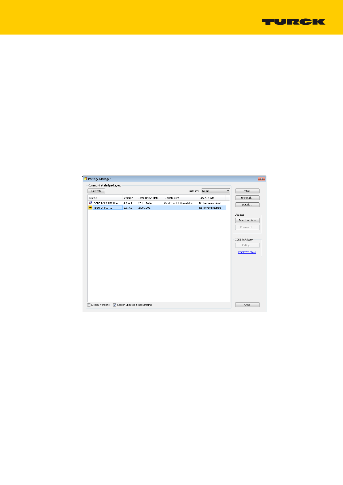
Install the package using the CODESYS Package Manager "Tools Package Manager".
2017/06
Fig. 1: Package Manager in CODESYS
The CODESYS package contains all necessary files:
CODESYS Device Description,
CODESYS libraries,
GSDML file,
EDS-file,
…
5
Page 8
Creating a CODESYS Project and Configuring the Network
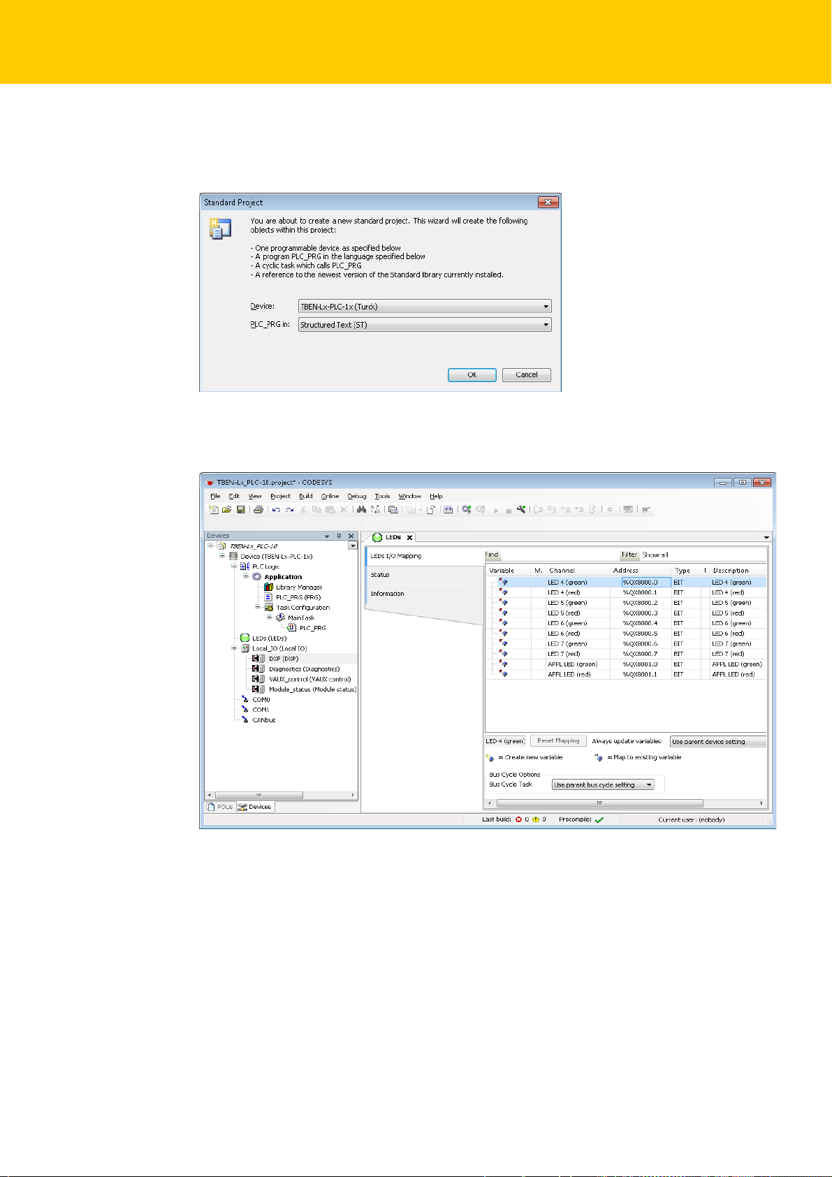
2.2 Create CODESYS Standard Project with TBEN-L-PLC-
Create a new standard project with TBEN-L-PLC- as CODESYS device.
Fig. 2: Selecting the TBEN-L-PLC- as CODESYS device
The CODESYS project is created.
Fig. 3: CODESYS project
6
Hans Turck GmbH & Co. KG | T +49 208 4952-0 | F +49 208 4952-264 | more@turck.com | www.turck.com
Page 9
Additionally to the PLC logic, the project contains:
5 LEDs for free use in the program (LEDs)
– Each LED uses 2 bit in the process output data of the device. They are automatically mapped to
the output bits %QX8000.0 to QX8001.1 (see
Local IO (Local_IO)
– Process data and configuration of the device's local I/Os and the VAUX diagnostics
– Diagnostics of the local I/Os and module status.
2 serial interfaces (COM0 and COM1)
– Connection of RS232 and RS485 devices
1 CAN interface (CANbus)
– Use of the device as CANopen Device, CANopen Manager or as
SAE J1939 Manager
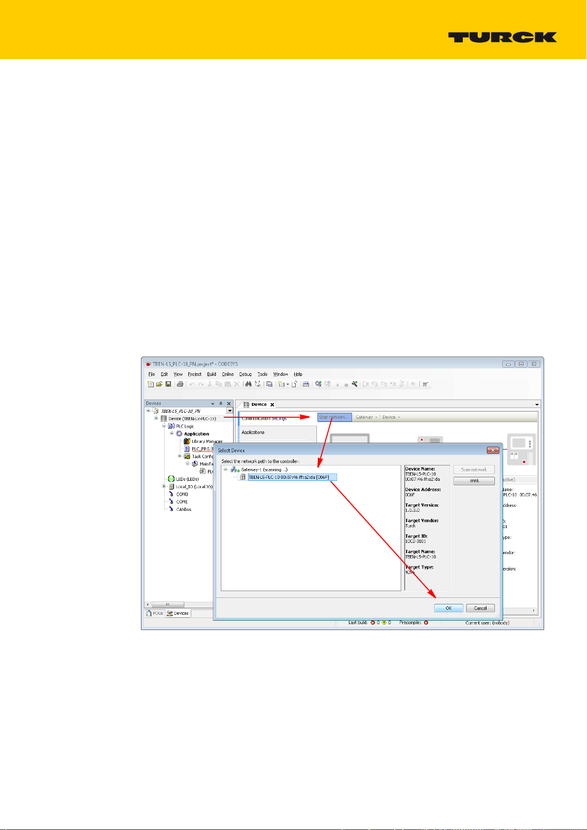
2.3 Configuring the Network
Double clicking the entry "Device (TBEN-Lx-PLC-1x)" opens the "device" tab.
Scan the network for TBEN-L…-PLC-10 via the "scan network…" button and select the device.
Fig. 3: CODESYS project (page 6)).
2017/06
Fig. 4: Scan the network and select TBEN-L…-PLC-10 as device
7
Page 10
Creating a CODESYS Project and Configuring the Network
2.3.1 Configuring the Ethernet Interface
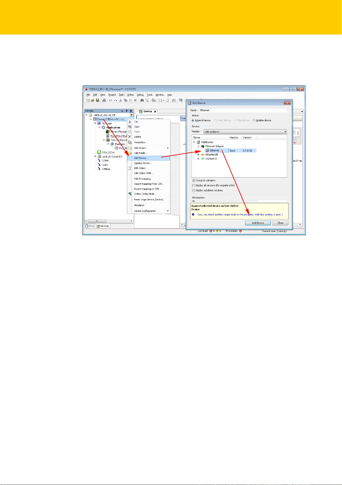
Right clicking the entry "Device (TBEN-Lx-PLC-1x)" opens context menu.
Add the Ethernet interface via the "Add device…" function.
Fig. 5: Adding the Ethernet interface
The Ethernet interface is added to the project tree.
8
Hans Turck GmbH & Co. KG | T +49 208 4952-0 | F +49 208 4952-264 | more@turck.com | www.turck.com
Page 11

Open the "Ethernet" tab by double clicking the Ethernet interface in the project tree.
Fig. 6: Configuring the Ethernet interface
The IP address of the network interface corresponds to the IP address of the TBEN-L-PLC-
Select "eth0" under "network interface".
The IP address is set automatically.
2017/06
9
Page 12

Creating a CODESYS Project and Configuring the Network
10
Hans Turck GmbH & Co. KG | T +49 208 4952-0 | F +49 208 4952-264 | more@turck.com | www.turck.com
Page 13

3 Using the Device as PROFINET Controller
Used Hardware
PLC:
–
TBEN-L5-PLC-10
I/Os:
–
TBEN-S1-8DXP
– TBEN-S2-4IOL with:
IO-Link port 1: Turck temperature sensor, TS-530-LI2UPN8X-H1141-L016, IO-Link V1.0
IO-Link port 2: generic port configuration, one bit each in- and output data
IO-Link port 3: Turck ultrasonic sensor, RU40U-M18E-LiU2PN8X2T-H1151, IO-Link V1.1
IO-Link port 4: generic port configuration, used as digital input
–
BL20-E-GW-EN with:
I/O module 1: BL20-E-2CNT-2PWM
I/O module 2: BL20-2DO-24VDC-0.5A-P
I/O module 3: BL20-2AI-I(0/4…20MA)
Used Software
CODESYS V3, 3.5.8.10
TBEN-L…-PLC-1…_V1.0.3.0.package
3.1 Creating a CODESYS Project and Configuring the Network
Create CODESYS project and configure the network according to Kapitel 2, Creating a CODE-
SYS Project and Configuring the Network.
2017/06
11
Page 14

Using the Device as PROFINET Controller
3.2 Configuring the Device as PROFINET Controller
Properties Compact controller
Max. number of devices 64 64
Min. cycle time 1 ms 1 ms
Max. number of devices at 1 ms
AThis information refers to standard PROFINET devices with up to 4 byte of process data as for example digital I/O
modules. For PROFINET devices with much more process data (50 …400 byte) as for example IO-Link, RFID or
serial COM interfaces, the cycle time has to be increased to 2, 4 or 8 ms.
A 81
3.2.1 Adding the PROFINET Controller to the Project
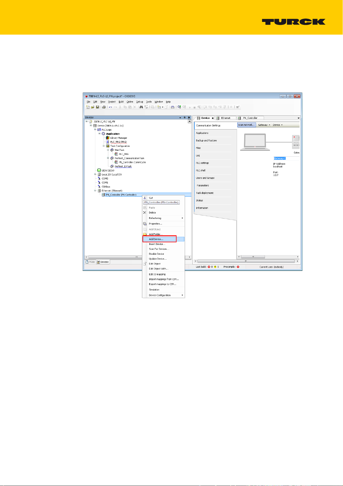
The PN-Controller from 3S – Smart Software Solutions GmbH is used.
Add the PN-Controller to the Ethernet interface using the "Add device…" function.
TBEN-L…PLC-10
HMI/PLC
TX500
12
Fig. 7: Adding the PN-Controller
Hans Turck GmbH & Co. KG | T +49 208 4952-0 | F +49 208 4952-264 | more@turck.com | www.turck.com
Page 15

The PROFINET controller is added to the project tree.
Fig. 8: PN-Controller in project tree
NOTE
The Device addresses under "Default Slave IP Parameter" and the Ethernet interface of the
TBEN-L-PLC- have to be in the same subnet.
3.2.2 PROFINET tasks in CODESYS
The following PROFINET tasks are automatically added to the project as soon as a
PROFINET controller is added to the Ethernet interface.
Profinet_CommunicationTask
This task includes the acyclic communication services, such as establishing connections, configuration of slaves and diagnostics. These services are not time-critical due to very weak real-time
requirements. Therefore the task is low priority (default: priority 30, interval 10 ms). In applications with a large amount of slaves it can be necessary to extend the cycle time.
Profinet_IOTask
This task is responsible for the PROFINET IO real-time data exchange. It controls the PROFINETMaster-Stack. The task should be set to high priority (default: priority 1, interval 1 ms).
2017/06
13
Page 16

Using the Device as PROFINET Controller
3.3 Configuring PROFINET Devices
In this example, the following Turck multiprotocol devices are used as PROFINET devices:
–
TBEN-S1-8DXP
– TBEN-S2-4IOL
– BL20-E-GW-EN
3.3.1 Installing the GSDML-files
Download the GSDML files from www.turck.com and install them in the CODESYS Device
Repository.
14
Fig. 9: CODESYS Device Repository
Hans Turck GmbH & Co. KG | T +49 208 4952-0 | F +49 208 4952-264 | more@turck.com | www.turck.com
Page 17

3.3.2 Scan Network for PROFINET Devices
Start the device search via the "Scan for devices…" function at the PROFINET controller.
Fig. 10: Search devices
The found devices can either be selected separately or all found devices can be added to the
project via the "Copy All Devices to Project" button.
2017/06
15
Page 18

Using the Device as PROFINET Controller
Fig. 11: Searching devices
The devices are added to the project tree.
Modular Turck devices, as the BL20 station in the example, are added with all connected I/O
modules.
The configuration of the IO-Link ports of the TBEN-S2-4IOL in the example is done manually
afterwards (see Configuring the TBEN-S2-4IOL (IO-Link Master) (page 20)).
16
Hans Turck GmbH & Co. KG | T +49 208 4952-0 | F +49 208 4952-264 | more@turck.com | www.turck.com
Page 19
3.3.3 Adding PROFINET Devices Manually
As an alternative for the scanning of the network, PROFINET devices can also be add manually to
PROFINET.
Add external PROFINET devices using the "Add device…" function.
2017/06
Fig. 12: Adding external PROFINET devices
17
Page 20

Using the Device as PROFINET Controller
Select the PROFINET devices from the device catalog and add them to the project.
Fig. 13: Adding external PROFINET devices
18
Hans Turck GmbH & Co. KG | T +49 208 4952-0 | F +49 208 4952-264 | more@turck.com | www.turck.com
Page 21

3.3.4 Configuring the BL20 station
For modular PROFINET devices, first of all select the gateway (in this example the BL20-E- GW-
EN).
Right-click the gateway and use the "Add device" function to add the I/O modules in the order
in which they follow the gateway.
Fig. 14: Adding I/O modules to the BL20 gateway
2017/06
19
Page 22
Using the Device as PROFINET Controller
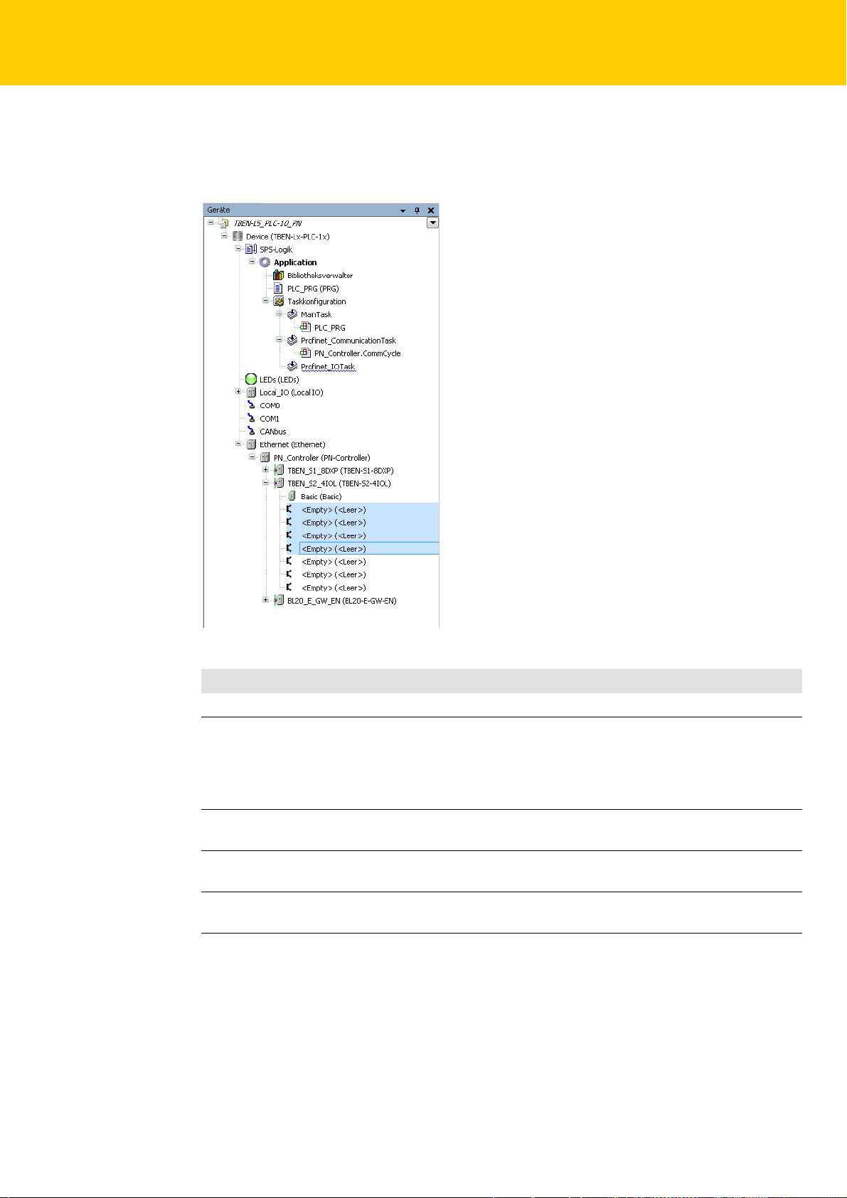
3.3.5 Configuring the TBEN-S2-4IOL (IO-Link Master)
The TBEN-S2-4IOL is shown in the project tree as a modular slave with one basic slot and seven
empty slots.
Fig. 15: TBEN-S2-4IOL in the project tree
Slot/empty slot Meaning
1
2 - 5 IO-Link ports For the configuration of the four
6 Diagnostics Optional mapping of the diagnostics (IO-Link and
7 IO-Link Events Optional mapping of the diagnostics (IO-Link and
8 Module status Optional mapping of the diagnostics (IO-Link and
Basic
DXP-channels of the device (DXP 2, 4, 6, and 8)
IO-Link ports.
Specific or generic configuration of the IO-Link
ports (see Configuring the Empty Slots 2 – 5 (IO-
Link-Ports) (page 21)).
DXP-diagnostics) into the master's process image.
DXP-diagnostics) into the master's process image.
DXP-diagnostics) into the master's process image.
20
Hans Turck GmbH & Co. KG | T +49 208 4952-0 | F +49 208 4952-264 | more@turck.com | www.turck.com
Page 23

Configuring the Empty Slots 2 – 5 (IO-Link-Ports)
Device configuration in the example:
TBEN-S2-4IOL with:
IO-Link port 1: Turck temperature sensor, TS-530-LI2UPN8X-H1141-L016, IO-Link V1.0
IO-Link port 2: generic port configuration, one bit each in- and output data
IO-Link port 3: Turck ultrasonic sensor, RU40U-M18E-LiU2PN8X2T-H1151, IO-Link V1.1
IO-Link port 4: generic port configuration, used as digital input
Use the "Plug device…" function to select an IO-Link device for the respective empty slot.
The configuration is either done via SIDI (Simple IO-Link Device Integration) or as generic configuration. In this example port 1 and 3 are used with a specific sensor, port 2 with a generic sensor with
one byte IO-Link input data and one byte IO-link output data. Port 4 is configured generically as digital input.
NOTE
By means of the "Simple IO-Link Device Integration (SIDI)", Turck IO-Link devices can
directly be selected from the device GSDML in PROFINET.
2017/06
Fig. 16: TBEN-S2-4IOL, "Plug device…" and select port configuration
21
Page 24

Using the Device as PROFINET Controller
Select the entry of the temperature sensor "TS-530-LI2UPN8X-family" under "Port configuration
generic" and plug the device.
Select "TS-530-LI2UPN8X-family" and "Plug device…".
Fig. 17: Select TS-530-LI2UPN8X-family
22
Hans Turck GmbH & Co. KG | T +49 208 4952-0 | F +49 208 4952-264 | more@turck.com | www.turck.com
Page 25

Configure port 2 generically and select the entry "IN 1 BYTE/OUT 1 BYTE".
Fig. 18: Generic port configuration
Select the entry of the ultrasonic sensor "RU40U-M18E-LiU2PN8X2T-H1151" under "Port config-
uration specific" and plug the device.
2017/06
23
Page 26

Using the Device as PROFINET Controller
Configure port 4 generically and select the entry "DI".
Fig. 19: IO-Link Port Configuration
24
Hans Turck GmbH & Co. KG | T +49 208 4952-0 | F +49 208 4952-264 | more@turck.com | www.turck.com
Page 27

Configuring the Empty Slots 6 – 8 (Diagnostics, IO-Link-Events, Module Status)
The empty slots 6 to 8 allow the mapping of channel diagnostics, IO-Link Events and the modules
status to the process image of the IO-Link master.
Select the entry for the respective empty slot using the "Plug device…" function.
2017/06
Fig. 20: TBEN-S2-4IOL: Add diagnostics, IO-Link Events and module status
25
Page 28

Using the Device as PROFINET Controller
Diagnostics
Fig. 21: TBEN-S2-4IOL: Diagnostics in the process image
26
Hans Turck GmbH & Co. KG | T +49 208 4952-0 | F +49 208 4952-264 | more@turck.com | www.turck.com
Page 29

IO-Link Events
Fig. 22: TBEN-S2-4IOL: IO-Link Events in the process image
2017/06
27
Page 30

Using the Device as PROFINET Controller
Module status
Fig. 23: TBEN-S2-4IOL: Module status in the process image
28
Hans Turck GmbH & Co. KG | T +49 208 4952-0 | F +49 208 4952-264 | more@turck.com | www.turck.com
Page 31

3.4 Communication Settings for PROFINET Devices
Open the device's configuration tab by double clicking the entry of the respective PROFINET
device in the project tree.
3.4.1 Assigning the IP Address and the Station Name
Assign a PROFINET device name and an IP address and, if necessary, adapt the parameters "Send
Clock", "Reduction Ratio2 and "Phase" to the application.
NOTE
Assigning an IP address or a station name to the devices is not necessary if the devices
have been automatically read in using the "Scan for Devices" function (see Scan Network
for PROFINET Devices (page 15)).
2017/06
Fig. 24: Configuring external PROFINET devices
NOTE
The IP addresses of the PROFINET Devices and the PN Controller have to be in the same
subnet.
29
Page 32

Using the Device as PROFINET Controller
PROFINET Update Time
Reduction Ratio = Anzahl der Phasen
Send Clock
Phase 1 Phase 2 Phase 3 Phase 4
3.4.2 Setting the communication parameters (Send Clock, Reduction Ratio, Phase)
Send Clock (ms):
Send clock time in milliseconds
Reduction Ratio:
Scaling factor
The transmission interval results from the Send Clock × Reduction Ratio. Therefore, a Send Clock
of 1ms and a Reduction Ratio of 4 means that I/O data is sent every 4 ms.
Phase:
With a Reduction Ratio of n, the transmission interval is subdivided into phases 1 to n (where
transmission is in one phase only). The phase for transmission can be determined for the purpose
of load distribution.
Fig. 25: PROFINET Update Time
Fig. 26: Settings for the PROFINET device
With the settings "Send Clock" = 1 ms and "Reduction Ratio" = 4 the PROFINET Cycle Time (or Update
Time) is divided into four phases of 1 ms each. A PROFINET device with these settings is updated
every 4 ms. The PROFINET Update Time is thus the result of the multiplication of "Send Clock" and
"Reduction Ratio".
PROFINET Update Time = Send Clock × Reduction Ratio
The parameter "Phase" defines in which phase this PROFINET device is updated. In PROFINET networks with several devices the devices can be split to the different phases. This helps the master to
optimize the PN data transfer.
30
Hans Turck GmbH & Co. KG | T +49 208 4952-0 | F +49 208 4952-264 | more@turck.com | www.turck.com
Page 33

3.5 Requesting the Device Status in the Program
The device status can be requested in the program by entering the PROFINET device instance and
the requested function.
Instance.Status;
Example:
Request, if the device is in cyclic data exchange:
tben_s2_4IOL.xRunning;
2017/06
Fig. 27: Requesting the device status in the program
31
Page 34

Using the Device as PROFINET Controller
3.6 Using IO-Link Function Blocks for CODESYS
For acyclic access to the Turck IO-Link master devices (in the example TBEN-S2-4IOL) as well as to
the connected IO-Link devices, Turck offers the following function blocks:
IOL_CALL (in accordance with IO-Link specification)
single acyclic accesses
IOL_WriteParamterList:
sending a parameter list for e. g. initial parameterization of IO-Link devices
The function blocks are part of the turck CODEYS library "IO-Link CALL PROFINET", V1.0.2.0 or higher.
Further information about the function blocks and their usage can be found in the operating
instructions of the Turck IO-Link master or in the function block description in CODESYS.
Fig. 28: Function block IOL_CALL
32
Hans Turck GmbH & Co. KG | T +49 208 4952-0 | F +49 208 4952-264 | more@turck.com | www.turck.com
Page 35

Fig. 29: Function block IOL_WriteParameterList
2017/06
33
Page 36

Using the Device as PROFINET Controller
34
Hans Turck GmbH & Co. KG | T +49 208 4952-0 | F +49 208 4952-264 | more@turck.com | www.turck.com
Page 37

4 Using the Device as PROFINET Device
Properties
max. number of I/O data 1024 byte in total
(512 IN + 512 OUT)
Used Hardware
Controller.
–
Siemens CPU 1515-2 PN
Device:
–
TBEN-L5-PLC-10
Used Software
CODESYS V3, 3.5.8.10
TBEN-L…-PLC-1…_V1.0.3.0.package
TIA Portal V13
GSDML-V2.3-TURCK-CDS3_PN_Device-20151208-010322.xml
4.1 Creating a CODESYS Project and Configuring the Network
Create CODESYS project and configure the network according to Kapitel 2, Creating a CODE-
SYS Project and Configuring the Network.
2017/06
35
Page 38

Using the Device as PROFINET Device
4.2 Configuring the PROFINET Device
4.2.1 Adding the PROFINET Device to the Project
The Turck PROFINET Device is used.
Add the Profinet_Device to Ethernet using the "Add Device" function.
Fig. 30: Add PROFINET Device
36
Hans Turck GmbH & Co. KG | T +49 208 4952-0 | F +49 208 4952-264 | more@turck.com | www.turck.com
Page 39

Configure the in- and output data lengths which have to be exchanged with the higher-level
PROFINET Master. Therefore add the respective process data entries.
Fig. 31: Configuring the PROFINET Device
NOTE
Please observe the following for the configuration of the I/O data:
The CODESYS input data have to be have to be configured as output data in the PROFINET
Controller configuration, the CODESYS output data have to be configured as input data.
The data thus have to be configured in reverse order in the PROFINET Controller configuration (see also Configuring the in- and output data (page 41)).
2017/06
37
Page 40

Using the Device as PROFINET Device
Which data will be mapped into the configured input and output data, depends on assignments in
the PLC program or in the I/O mapping of the TBEN-L-PLC-.
Fig. 32: PROFINET Device data mapping
NOTE
The PROFINET Device shows an error as long as a connection to the PROFINET Controller
is established.
38
Hans Turck GmbH & Co. KG | T +49 208 4952-0 | F +49 208 4952-264 | more@turck.com | www.turck.com
Page 41

4.2.2 Configuring the PROFINET Device (CDS3 PN-Device) in TIA Portal
The following example shows the CDS3 PN-Device configuration in TIA Portal V13 from Siemens.
The PROFINET-CODESYS-device is configured as standard PROFINET Device in TIA Portal.
Installing the GSDML-file
Install the device's GSDML-file (GSDML-V2.3-TURCK-CDS3_PN_Device--.xml) in TIA Portal. It
can be downloaded at the respective product fromwww.turck.com.
The device is added to the hardware catalog "CDS 3 PN Device".
Fig. 33: Configuring the PROFINET Device in TIA Portal
2017/06
39
Page 42

Using the Device as PROFINET Device
Configuring the PROFINET parameters
Like for all other PROFINET Device, the PROFINET-interface has to be configured for the CDS3 PNDevice" in the project.
Set all necessary IP-settings and assign a PROFINET Device name or use the device name which
has already been assigned to the device.
Fig. 34: Settings PROFINET-interface (CDS3 PN Device)
40
Hans Turck GmbH & Co. KG | T +49 208 4952-0 | F +49 208 4952-264 | more@turck.com | www.turck.com
Page 43
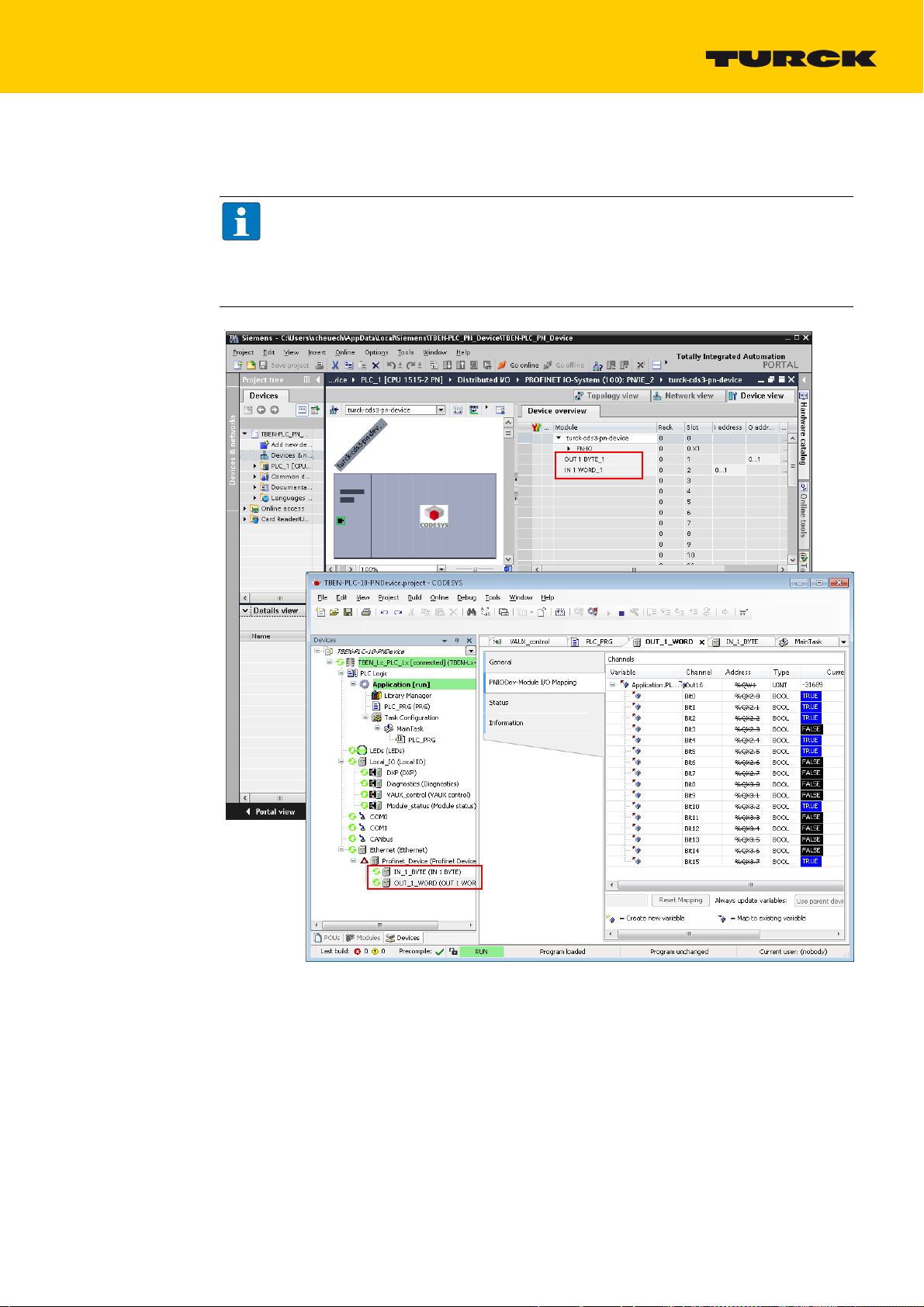
Configuring the in- and output data
Configure the in- and output data, which have to be exchanged with the CODESYS-device.
NOTE
The configuration of the data in TIA Portal has to be done in reverse order compared to
the configuration in CODESYS. Input data in TIA Portal are output-data in CODESYS, and
vice versa.
The configured data lengths have to match.
2017/06
Fig. 35: Configuration of in- and output data in TIA Portal/CODESYS
41
Page 44

Using the Device as PROFINET Device
After configuring the PROFINET Device in TIA Portal and starting the PN controller, the CODESYS
application with the PROFINET Device is running error free.
Fig. 36: CODESYS application with PROFINET Device
42
Hans Turck GmbH & Co. KG | T +49 208 4952-0 | F +49 208 4952-264 | more@turck.com | www.turck.com
Page 45

100000538 2017/06
28 subsidiaries and over
60 representations worldwide!
*100000538*
www.turck.com
 Loading...