

CDN2-IOM22-0032
• Advanced DeviceNet™ station
•
Two discrete inputs and two discrete outputs
CDN2-IOM22-0032
This busstop®station is designed to replace the
equivalent CDN station. The PLC will not need to be
reconfigured.
Note: There is no EDS file available for this station.
Each input connector provides V+, V-, and input. The
V+ provides power to the attached sensor. The V+ is
short-circuit protected and monitered as a group. The
input will work with a PNP sensor or dry contact to V+.
Each output connector provides Aux- and output.
Outputs are individually short-circuit protected and
monitored individually.
The node address can be set using the rotary switches
located under the device cover or through software node
commissioning. The unit automatically detects the
communication rate.
The CDN2-IOM22-0032 supports explicit messaging,
poll, change of state, and cyclic I/O messages. These
connections are established through UCMM or
predefined master/slave connection set.
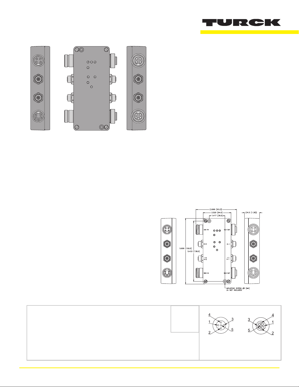
Dimensions
Applications
•
For wet and dry environments
•
For use with four 3-wire proximity and
photoelectric sensors, and four discrete
actuators
Features
•
PNP short-circuit protected inputs
•
0.5 amp short-circuit protected outputs
•
Rotary Address Switches
Connectors
DeviceNet
Style: 5-pin minifast
Cordset: Bus Line use RSC RKC 572-*M
Tee: Bus Line use RSC 2RKC 57
®
1 = Shield
2 = V+
3 = V4 = CAN_H
5 = CAN_I
Male Female
Through Bus
1 TURCK Inc. 10240356 Rev 1.0 06/05
TURCK
CDN2-IOM22-0032
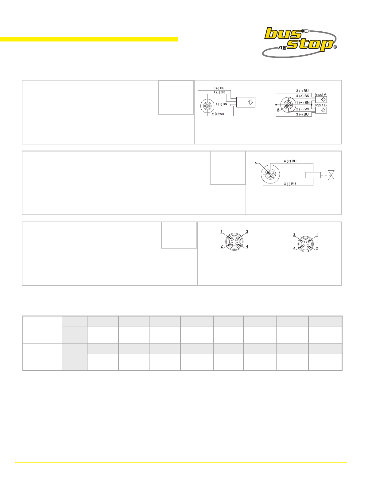
Connectors
Style: 5-pin eurofast
Cordset: Single Sensor use RK 4.4T-*-RS 4.4T
®
1 = V+
2 = Alarm
3 = V4 = Input
5 = PE
Type "G"
Style: 5-pin eurofast
Single Sensor
1 = N/C
2 = N/C
3 = GND
®
4 = Output
5 = N/C
Splitter & 2 Sensors
Cordset: Single Sensor use RK 4.4T-*-RS 4.4T
Field Wireable: Single Output use BS 8141-0
Aux Power
Style: 4-pin minifast
®
1 = Aux+
2 = E+
3 = E4 = Aux-
Single Output
Cordset: Aux Power use RSM RKM 46-*M
Tee: Bus Line use RSM 2RKM 57
Male Female
Auxiliary Power
I/O Data Mapping Vendor Code: 48 Product Code: 517
Input
Byte Bit 7 Bit 6 Bit 5 Bit 4 Bit 3 Bit 2 Bit 1 Bit 0
Data
0 OS-1 OS-0 IGS IGS A-1 A-0 I-1 I-0
Byte Bit 7 Bit 6 Bit 5 Bit 4 Bit 3 Bit 2 Bit 1 Bit 0
Output
Data
0 - - - - - - O-1 O-0
Abbreviations
I = Input Data (0= OFF, 1= ON) O = Output Data (0=OFF, 1=ON)
ISS = Input Short Status (0=Working, 1=Fault) OS = Output Status (0=Working, 1=Fault)
IOS = Input Open Status (0=Working, 1=Fault) OGS = Output Group Status (0=Working, 1=Fault)
2 TURCK Inc. 10240356 Rev 1.0 06/05

Module Specifications
Supply Voltage
CDN2-IOM22-0032
Two PNP Input and Two 0.5 A Output
Group Diagnostic
Bus Power
Internal Current Consumption
Auxiliary Power
Input Circuits (2) PNP 3-wire sensors or dry contacts
Input Voltage (V+)
Input Short-Circuit (V+)
Input Signal Current (Input)
Input Delay
Output Circuits (2) DC acutators
Output Voltage
Output Load Current
Open Circuit Current
I/O LED Indications
Module/Network LED Status
11-26 VDC
≤75 mA plus sum of sensor and output currents (from bus power)
18-26
11-26 VDC (from bus power)
<700 mA (total, short-circuit protected)
OFF <2 mA
ON 3.0-3.4 mA at 24 VDC
2.5 ms
18-26 VDC (from bus power)
0.5 A per output (from auxiliary power)
100 Hz
OFF = Off
Green = On
Green: Established connection
Flashing Green: Ready for connection
Flashing Red: Connection time-out, I/O short-circuit, or Aux Power
Failure
Red: Connection not possible
Flashing Amber: Detecting Autobaud Rate
Aux Power LED
ON = Auxiliary Power On
OFF = No Auxiliary Power
Adjustments via Rotary Switch
Address 0-63
3 TURCK Inc. 10240356 Rev 1.0 06/05
 Loading...