

Page 1
Capacitive Sensor Part Number Key
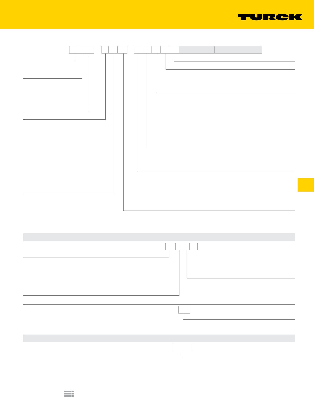
B C 10 - K 40 SR - F Z 3 X2 T Wiring Options* Special Option Codes**
Mounting
B = embeddable
N = nonembeddable
Principle of Operation
C = capacitive
CC = capacitive
(low dielectric targets)
CF = capacitive (noise immune)
CT = capacitive teach
Rated Operating Distance (mm)
Housing Style
Barrel - Metal
M = partial threading, chrome plated brass
Barrel - Plastic
K = smooth
KT = PVDF, smooth
P = full threading
PT = PVDF, full threading
S = partial threading
Rectangular
Q = metal or plastic, various rectangular styles
QF = plastic, Polypropylene rectangular style
Housing Diameter or Height (mm)
NOTE:
Part Number Keys are to assist in identication only.
Verify new part numbers with factory;
Some congurations are not possible.
Teach Button
Number of LEDs
(blank) = no LEDs
X = 1 LED
X2 = 2 LEDs
Voltage Range
AC/DC: (No SCP**)
3 = 20-250 VAC
DC:
4 = 10-65 VAC, polarity protected, pulsed SCP**
6 = 10-30 VAC, polarity protected, pulsed SCP
DC:
4 = 10-65 VDC, polarity protected, pulsed SCP**
6 = 10-30 VDC, polarity protected, pulsed SCP
**SCP = short-circuit and overload protection
Output
N = NPN transistor (current sinking)
P = PNP transistor (current sourcing)
Z = 2-wire AC or 2-wire AC/DC
Output Function
A = normally open (N.O.)
F = connection programmable (N.O. or N.C.)
R = normally closed (N.C.)
V = complementary outputs: one N.O., one N.C.
Y0 = NAMUR output, requires switching amplier
Y1 = NAMUR output, requires switching amplier/ATEX approved
Secondary Housing Modier
SR = straight terminal chamber
Wiring Options*
A. Connectorized Sensor
We reserve the right to make technical alterations without prior notice.
Connector Family
B1 = Minifast®, Metal, Male
B2 = Minifast, Plastic, Male
B3 = Microfast®, Metal, Male
H1 = Eurofast®, Metal or Plastic, Male
V1 = Picofast®, Metal, Male
Connector/Sensor Transition
1 = straight
B. Potted Cable
Special Option Codes**
Option Code
Example:
/S250 = No Potentiometer
/S400 = Rear LEDs (for Q14 and Q20 only)
Capacitive Sensors
BC10 - M30 - AP4X - H1 1 4 1
Wiring Conguration
Example:
1 = Standard
3 = N.C. DC Output on Pin 4 (for US)
Number of Pins
BC5 - S18 - AP4X - 7M
Cable Length
Blank = 2 Meter cable
7M = 7 Meter cable
BC10 - Q14 - AN4X - /S250
Turck Inc.
E2
 Loading...