

Page 1
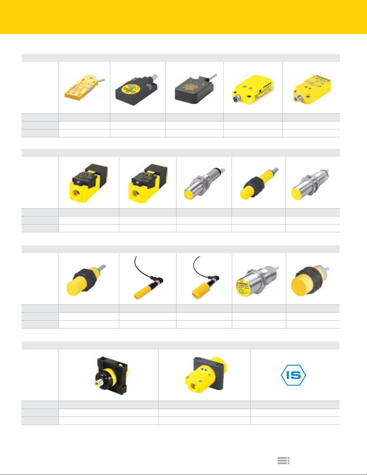
Capacitive Sensor SeIection Guide
Embeddable/Nonembeddable Rectangular
Housing 5.5 mm 8 mm 10 mm 14 mm 20 mm
Sensing Range 5 - 10 mm 5 mm 8 mm 10 - 15 mm 10 - 20 mm
Pages E3 E5 E5 E7 E9
Embeddable/Nonembeddable Rectangular and Barrels
Housing 40 mm 80 mm 12 mm 12 mm 18 mm
Sensing Range 20 - 30 mm 50 mm 3 mm 3 - 4.5 mm 5 mm
Pages E11 E11 E13 E13 E15
We reserve the right to make technical alterations without prior notice.
Embeddable/Nonembeddable Barrels
Housing 18 mm 18 mm BCT 30 mm BCT 30 mm 30 mm
Sensing Range 5 - 7.5 mm 5 - 7.5 mm 10 - 15 mm 10 mm 10 - 15 mm
Pages E17 E19 E19 E21 - 24 E25 - 28
Embeddable/Nonembeddable Plastic Barrels
Housing 34 mm 40 mm Variable
Sensing Range 15 - 23 mm 20 - 30 mm 5 - 10 mm
Pages E29 - 34 E29 - 32 E35
E1
Turck Inc.
Page 2
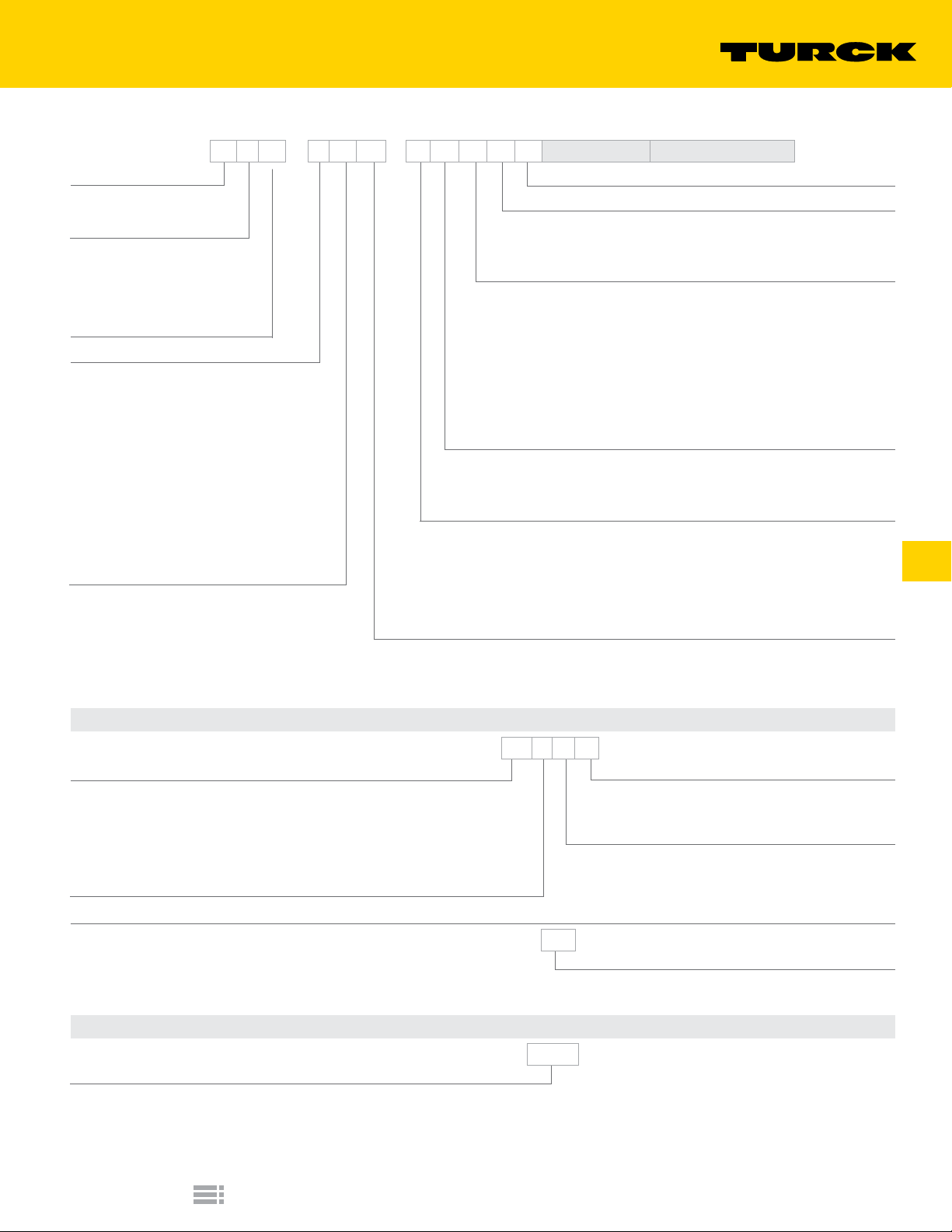
Capacitive Sensor Part Number Key
B C 10 - K 40 SR - F Z 3 X2 T Wiring Options* Special Option Codes**
Mounting
B = embeddable
N = nonembeddable
Principle of Operation
C = capacitive
CC = capacitive
(low dielectric targets)
CF = capacitive (noise immune)
CT = capacitive teach
Rated Operating Distance (mm)
Housing Style
Barrel - Metal
M = partial threading, chrome plated brass
Barrel - Plastic
K = smooth
KT = PVDF, smooth
P = full threading
PT = PVDF, full threading
S = partial threading
Rectangular
Q = metal or plastic, various rectangular styles
QF = plastic, Polypropylene rectangular style
Housing Diameter or Height (mm)
NOTE:
Part Number Keys are to assist in identication only.
Verify new part numbers with factory;
Some congurations are not possible.
Teach Button
Number of LEDs
(blank) = no LEDs
X = 1 LED
X2 = 2 LEDs
Voltage Range
AC/DC: (No SCP**)
3 = 20-250 VAC
DC:
4 = 10-65 VAC, polarity protected, pulsed SCP**
6 = 10-30 VAC, polarity protected, pulsed SCP
DC:
4 = 10-65 VDC, polarity protected, pulsed SCP**
6 = 10-30 VDC, polarity protected, pulsed SCP
**SCP = short-circuit and overload protection
Output
N = NPN transistor (current sinking)
P = PNP transistor (current sourcing)
Z = 2-wire AC or 2-wire AC/DC
Output Function
A = normally open (N.O.)
F = connection programmable (N.O. or N.C.)
R = normally closed (N.C.)
V = complementary outputs: one N.O., one N.C.
Y0 = NAMUR output, requires switching amplier
Y1 = NAMUR output, requires switching amplier/ATEX approved
Secondary Housing Modier
SR = straight terminal chamber
Wiring Options*
A. Connectorized Sensor
We reserve the right to make technical alterations without prior notice.
Connector Family
B1 = Minifast®, Metal, Male
B2 = Minifast, Plastic, Male
B3 = Microfast®, Metal, Male
H1 = Eurofast®, Metal or Plastic, Male
V1 = Picofast®, Metal, Male
Connector/Sensor Transition
1 = straight
B. Potted Cable
Special Option Codes**
Option Code
Example:
/S250 = No Potentiometer
/S400 = Rear LEDs (for Q14 and Q20 only)
Capacitive Sensors
BC10 - M30 - AP4X - H1 1 4 1
Wiring Conguration
Example:
1 = Standard
3 = N.C. DC Output on Pin 4 (for US)
Number of Pins
BC5 - S18 - AP4X - 7M
Cable Length
Blank = 2 Meter cable
7M = 7 Meter cable
BC10 - Q14 - AN4X - /S250
Turck Inc.
E2
Page 3
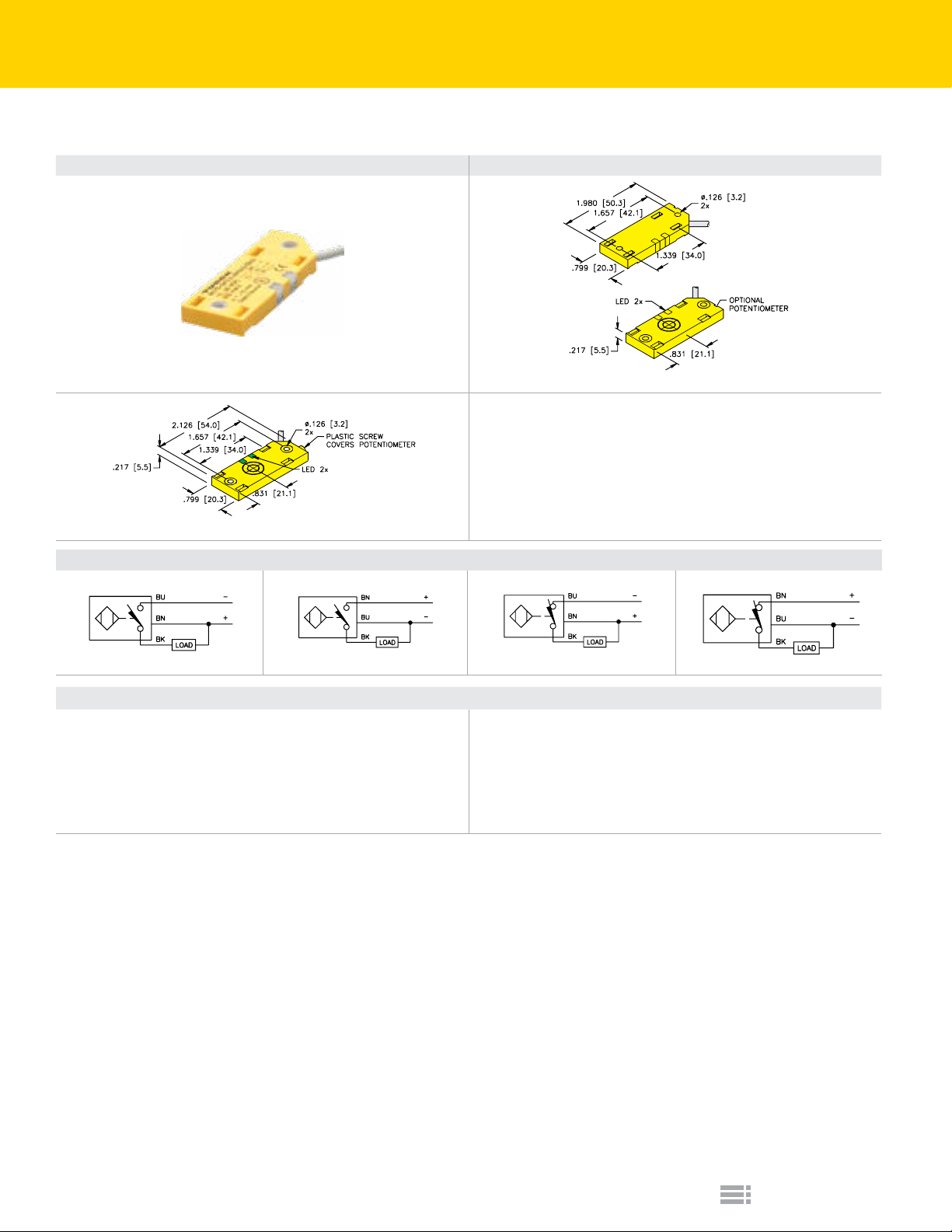
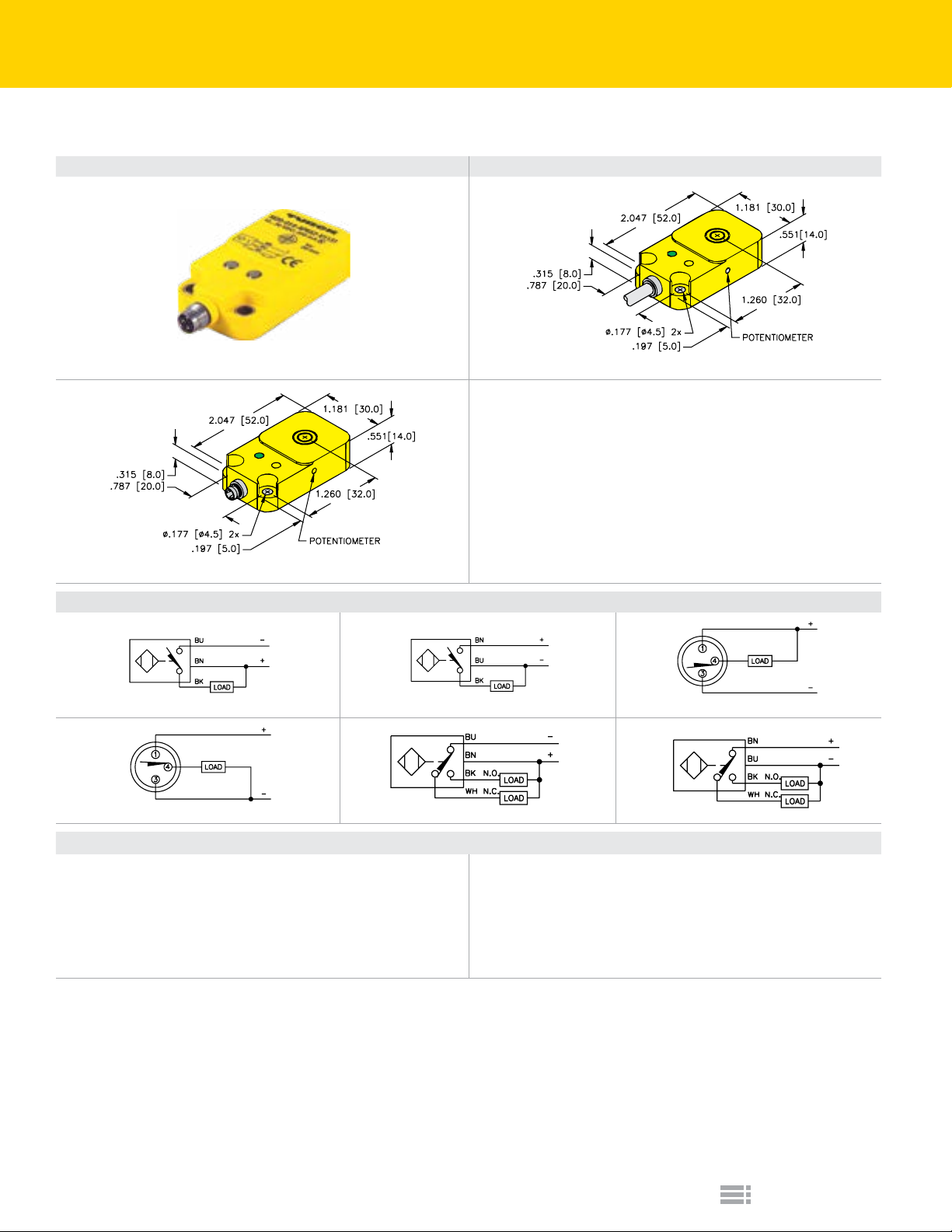
Capacitive Sensors | QF5.5
Top Sensing Thin Qpak Housing with DC Outputs
Housing Style Dimension Drawings
A
5.5 mm - Potted-In Cable
B
5.5 mm - Potted-In Cable, w/Potentiometer Cover
Wiring Diagrams/Mating Cordsets
1 2 3 4
We reserve the right to make technical alterations without prior notice.
A11
Ripple:
Differential Travel (Hysteresis):
Voltage Drop Across Conducting Sensor:
Trigger Current for Short Circuit Protection:
Off-State (Leakage) Current:
No-Load Current:
Power-On Effect:
3 and 4-wire DC Capacitive - (AP, RP, AN, RN, VN, VP)
≤10%
2-20% (5% typical)
≤1.8 V
≥220 mA
≤0.1 mA
≤15 mA
Per IEC 947-5-2
Reverse Polarity Protection:
Wire-Break Protection:
Transient Protection:
Shock:
Vibration:
Repeatability:
Temperature Drift:
Incorporated
Incorporated
Per EN 60947-5-2
30 g, 11 ms
55 Hz, 1 mm Amplitude, in all 3 Planes
≤2% of Rated Operating Distance
<±20% of Rated Operating Distance
E3
Turck Inc.
Page 4

Capacitive Sensors | QF5.5
Top Sensing Thin Qpak Housing with DC Outputs
Part Number/
ID Number
BC5-QF5.5-AN6X2/S250
2620120
BC10-QF5.5-AN6X2
2620121
BC10-QF5.5-AN6X2/S250
2620119
BC10-QF5.5-RN6X2
2620128
BC5-QF5.5-AP6X2/S250
2620116
BC5-QF5.5-RP6X2/S250
2620127
BC10-QF5.5-AP6X2
2620117
BC10-QF5.5-AP6X2/S250
2620115
BC10-QF5.5-RP6X2
2620126
BC10-QF5.5-RP6X2/S250
2620124
BC10-QF5.5-AN6X2/S932
2620137
BC10-QF5.5-RN6X2/S932
2620140
BC10-QF5.5-AP6X2/S932
2620109
We reserve the right to make technical alterations without prior notice.
BC10-QF5.5-RP6X2/S932
2620141
Notes:
/S250: Without switch point adjustment potentiometer
/S932: Adjustment potentiometer with protective cover, and non-metallic mounting bushing
Features
Normally Closed 10 10 3-wire DC NPN 10-30 VDC 100 ≤200 -25 to +70 IP67 PP PP GN YE 2M/TPU A 3 A11
Normally Closed 5 5 3-wire DC NPN 10-30 VDC 100 ≤200 -25 to +70 IP67 PP PP GN YE 2M/TPU A 4 A11
Normally Closed 10 10 3-wire DC NPN 10-30 VDC 100 ≤200 -25 to +70 IP67 PP PP GN YE 2M/TPU A 4 A11
Normally Closed 10 10 3-wire DC NPN 10-30 VDC 100 ≤200 -25 to +70 IP67 PP PP GN YE 2M/TPU A 4 A11
Normally Closed 10 10 3-wire DC NPN 10-30 VDC 100 ≤200 -25 to +70 IP67 PP PP GN YE 2M/TPU B 3 A11
Normally Closed 10 10 3-wire DC NPN 10-30 VDC 100 ≤200 -25 to +70 IP67 PP PP GN YE 2M/TPU B 4 A11
Embeddable Range (mm)
Nonembeddable Range (mm)
5 5 3-wire DC NPN 10-30 VDC 100 ≤200 -25 to +70 IP67 PP PP GN YE 2M/TPU A 1 A11
10 10 3-wire DC NPN 10-30 VDC 100 ≤200 -25 to +70 IP67 PP PP GN YE 2M/TPU A 1 A11
10 10 3-wire DC NPN 10-30 VDC 100 ≤200 -25 to +70 IP67 PP PP GN YE 2M/TPU A 1 A11
5 5 3-wire DC NPN 10-30 VDC 100 ≤200 -25 to +70 IP67 PP PP GN YE 2M/TPU A 2 A11
10 10 3-wire DC NPN 10-30 VDC 100 ≤200 -25 to +70 IP67 PP PP GN YE 2M/TPU A 2 A11
10 10 3-wire DC NPN 10-30 VDC 100 ≤200 -25 to +70 IP67 PP PP GN YE 2M/TPU A 2 A11
10 10 3-wire DC NPN 10-30 VDC 100 ≤200 -25 to +70 IP67 PP PP GN YE 2M/TPU B 1 A11
10 10 3-wire DC NPN 10-30 VDC 100 ≤200 -25 to +70 IP67 PP PP GN YE 2M/TPU B 2 A11
Output
Voltage
Switching Freq. (Hz)
Operating Current (mA)
Operating Temp. (°C)
Protection
Housing Material
Front Cap/Face
Power LED
Output LED
Cable Length/Jacket
Dimension Drawings
Wiring Diagrams
Spec List
Capacitive Sensors
Turck Inc.
E4
Page 5
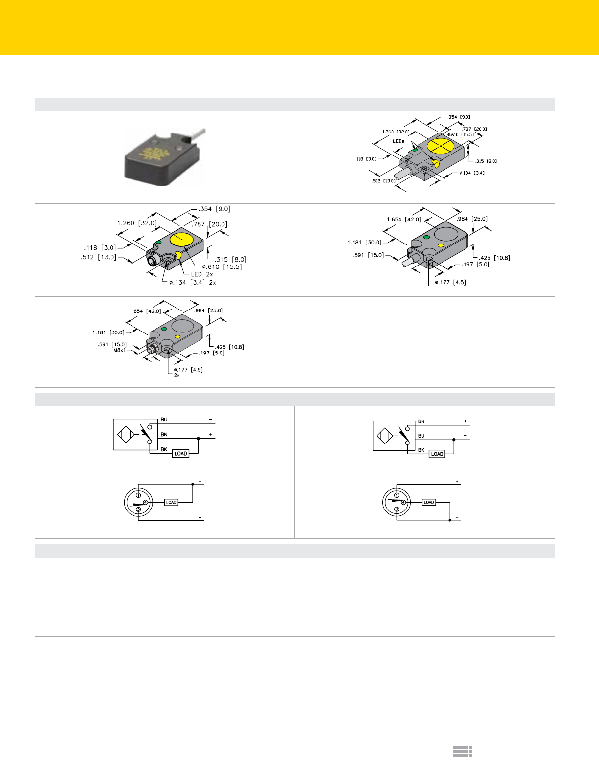
Capacitive Sensors | Q08 & Q10
Top Sensing Qpak Housing with DC Outputs
Housing Style Dimension Drawings
B
A
8 mm - Potted-In Cable
C
8 mm - Picofast Connector
D
10 mm - Picofast Connector
Wiring Diagrams/Mating Cordsets
1 2
3
Mating Cordset: PKG 3Z-*
A11
Ripple:
Differential Travel (Hysteresis):
Voltage Drop Across Conducting Sensor:
Trigger Current for Short Circuit Protection:
Off-State (Leakage) Current:
No-Load Current:
Power-On Effect:
≤10%
2-20% (5% typical)
≤1.8 V
≥220 mA
≤0.1 mA
≤15 mA
Per IEC 947-5-2
3 and 4-wire DC Capacitive - (AP, RP, AN, RN, VN, VP)
10 mm - Potted-In Cable
We reserve the right to make technical alterations without prior notice.
4
Mating Cordset: PKG 3Z-*; PKG 3M-*
Reverse Polarity Protection:
Wire-Break Protection:
Transient Protection:
Shock:
Vibration:
Repeatability:
Temperature Drift:
Incorporated
Incorporated
Per EN 60947-5-2
30 g, 11 ms
55 Hz, 1 mm Amplitude, in all 3 Planes
≤2% of Rated Operating Distance
<±20% of Rated Operating Distance
E5
Turck Inc.
Page 6

Capacitive Sensors | Q08 & Q10
Top Sensing Qpak Housing with DC Outputs
Part Number/
ID Number
BC5-Q08-AN6X2/S250
26201
BC5-Q08-AP6X2/S250
26200
BC5-Q08-AN6X2-V1131/S250
26211
BC5-Q08-AP6X2-V1131/S250
26210
BC8-Q10-AN6X2/S250
2621203
BC8-Q10-AP6X2/S250
2621200
BC8-Q10-AP6X2-V1131/S250
2621201
Notes:
/S250: Without switch point adjustment potentiometer
We reserve the right to make technical alterations without prior notice.
Embeddable Range (mm)
Nonembeddable Range (mm)
5 5 3-wire DC NPN 10-30 VDC 100 ≤200 -25 to +70 IP67 Zinc PA 12 GN YE 2M/TPU A 1 A11
5 5 3-wire DC NPN 10-30 VDC 100 ≤200 -25 to +70 IP67 Zinc PA 12 GN YE 2M/TPU A 2 A11
5 5 3-wire DC NPN 10-30 VDC 100 ≤200 -25 to +70 IP67 Zinc PA 12 GN YE -- B 3 A11
5 5 3-wire DC NPN 10-30 VDC 100 ≤200 -25 to +70 IP67 Zinc PA 12 GN YE -- B 4 A11
8 8 3-wire DC NPN 10-30 VDC 100 ≤200 -25 to +70 IP67 PBT-GF30-V0 -- GN YE 2M/PVC C 1 A11
8 8 3-wire DC NPN 10-30 VDC 100 ≤200 -25 to +70 IP67 PBT-GF30-V0 -- GN YE 2M/PVC C 2 A11
8 8 3-wire DC NPN 10-30 VDC 100 ≤200 -25 to +70 IP67 PBT-GF30-V0 -- GN YE -- D 4 A11
Output
Voltage
Switching Freq. (Hz)
Operating Current (mA)
Operating Temp. (°C)
Protection
Housing Material
Front Cap/Face
Power LED
Output LED
Cable Length/Jacket
Dimension Drawings
Wiring Diagrams
Spec List
Capacitive Sensors
Turck Inc.
E6
Page 7
Capacitive Sensors | Q14
Top Sensing Qpak Housing with DC Outputs
Housing Style Dimension Drawings
B
A
14 mm - Potted-In Cable
We reserve the right to make technical alterations without prior notice.
14 mm - Picofast Connector
Wiring Diagrams/Mating Cordsets
1 2 3
4
Mating Cordset: PKG 3M-*
A11
Ripple:
Differential Travel (Hysteresis):
Voltage Drop Across Conducting Sensor:
Trigger Current for Short Circuit Protection:
Off-State (Leakage) Current:
No-Load Current:
Power-On Effect:
≤10%
2-20% (5% typical)
≤1.8 V
≥220 mA
≤0.1 mA
≤15 mA
Per IEC 947-5-2
5 6
3 and 4-wire DC Capacitive - (AP, RP, AN, RN, VN, VP)
Reverse Polarity Protection:
Wire-Break Protection:
Transient Protection:
Repeatability:
Temperature Drift:
Shock:
Vibration:
Mating Cordset: PKG 3M-*
Incorporated
Incorporated
Per EN 60947-5-2
30 g, 11 ms
55 Hz, 1 mm Amplitude, in all 3 Planes
≤2% of Rated Operating Distance
<±20% of Rated Operating Distance
E7
Turck Inc.
Page 8

Capacitive Sensors | Q14
Top Sensing Qpak Housing with DC Outputs
Part Number/
ID Number
BC10-Q14-AN4X2
2530010
BC10-Q14-AP4X2
2530001
BC10-Q14-VN4X2
2530030
BC10-Q14-VP4X2
2530020
BC10-Q14-AN4X2-V1131
2530011
BC10-Q14-AN4X2-V1131/S400
2530006
BC10-Q14-AP4X2-V1131
2530002
BC10-Q14-AP4X2-V1131/S400
2530004
We reserve the right to make technical alterations without prior notice.
Features
Embeddable Range (mm)
Nonembeddable Range (mm)
10 15 3-wire DC NPN
10 15 3-wire DC NPN
Comp.
Outputs
Comp.
Outputs
Rear LED 10 15 3-wire DC NPN
Rear LED 10 15 3-wire DC NPN
10 15 4-wire DC NPN
10 15 4-wire DC NPN
10 15 3-wire DC NPN
10 15 3-wire DC NPN
Output
Voltage
Switching Freq. (Hz)
Operating Current (mA)
10-65
100 ≤200 -25 to +70 IP67 PBT-GF30-V0 GN YE
VDC
10-65
100 ≤200 -25 to +70 IP67 PBT-GF30-V0 GN YE
VDC
10-65
100 ≤200 -25 to +70 IP67 PBT-GF30-V0 GN YE
VDC
10-65
100 ≤200 -25 to +70 IP67 PBT-GF30-V0 GN YE
VDC
10-65
100 ≤200 -25 to +70 IP67 PBT-GF30-V0 GN YE -- B 3 A11
VDC
10-65
100 ≤200 -25 to +70 IP67 PBT-GF30-V0 GN YE -- B 3 A11
VDC
10-65
100 ≤200 -25 to +70 IP67 PBT-GF30-V0 GN YE -- B 4 A11
VDC
10-65
100 ≤200 -25 to +70 IP67 PBT-GF30-V0 GN YE -- B 4 A11
VDC
Operating Temp. (°C)
Protection
Housing Material
Power LED
Output LED
2M/
PVC
2M/
PVC
2M/
PVC
2M/
PVC
Cable Length/Jacket
A 1 A11
A 2 A11
A 5 A11
A 6 A11
Dimension Drawings
Wiring Diagrams
Spec List
Capacitive Sensors
Turck Inc.
E8
Page 9
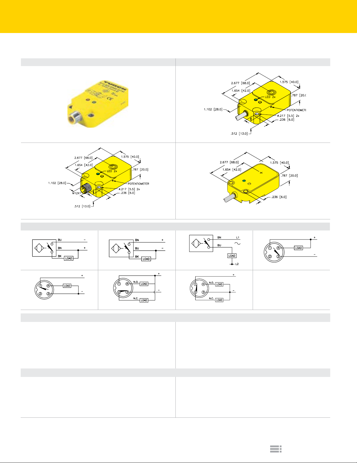
Capacitive Sensors | Q20
Top Sensing Qpak Housing with DC or AC Outputs
Housing Style Dimension Drawings
B
A
20 mm - Potted-In Cable
C
We reserve the right to make technical alterations without prior notice.
20 mm - Eurofast Connector
Wiring Diagrams/Mating Cordsets
20 mm - Potted-In Cable
1 2 3 4
5
Mating Cordset: RK 4T-*
A11
Differential Travel (Hysteresis):
Voltage Drop Across Conducting Sensor:
Trigger Current for Short Circuit Protection:
Off-State (Leakage) Current:
No-Load Current:
Power-On Effect:
A12
Line Frequency:
Differential Travel (Hysteresis):
Continuous Load Current:
Voltage Drop Across Conducting Sensor:
Off-State (Leakage) Current:
Minimum Load Current:
Ripple:
6
Mating Cordset: RK 4.4T-*
≤10%
2-20% (5% typical)
≤1.8 V
≥220 mA
≤0.1 mA
≤15 mA
Per IEC 947-5-2
≥50... ≤60 Hz
2-20% (5% typical)
≤500 mA
≤7.0 V
≤1.7 mA
≥5.0 mA
7
Mating Cordset: RK 4.4T-*
3 and 4-wire DC Capacitive - (AP, RP, AN, RN, VN, VP)
Reverse Polarity Protection:
Wire-Break Protection:
Transient Protection:
Shock:
Vibration:
Repeatability:
Temperature Drift:
2-wire AC Capacitive - (AZ, RZ)
Power-On Effect:
Transient Protection:
Shock:
Vibration:
Repeatability:
Temperature Drift:
Mating Cordset: RK 4T-*
Incorporated
Incorporated
Per EN 60947-5-2
30 g, 11 ms
55 Hz, 1 mm Amplitude, in all 3 Planes
≤2% of Rated Operating Distance
<±20% of Rated Operating Distance
Per IEC 947-5-2
Per EN 60947-5-2
30 g, 11 ms
55 Hz, 1 mm Amplitude, in all 3 Planes
≤2% of Rated Operating Distance
<±20% of Rated Operating Distance
E9
Turck Inc.
Page 10

Capacitive Sensors | Q20
Top Sensing Qpak Housing with DC or AC Outputs
Part Number/
ID Number
BC20-Q20-AN4X2
2530110
BC20-Q20-AN4X2/S400
2530104
BC20-Q20-AP4X2
2530100
BC20-Q20-AZ3X2
4352000
BC20-Q20-AZ3X2/S400
2310005
BC20-Q20-AN4X2-H1141
2530111
BC20-Q20-AP4X2-H1141
2530101
BC20-Q20-AP4X2-H1141/S400
2530103
BC20-Q20-VN4X2-H1141
2530131
BC20-Q20-VN4X2-H1141/S400
2530124
BC20-Q20-VP4X2-H1141
2530121
We reserve the right to make technical alterations without prior notice.
Features
Rear LED 20 30 3-wire DC NPN
Rear LED 20 30 2-wire AC
Rear LED 20 30 3-wire DC PNP
Comp. Outputs 20 30 4-wire DC NPN
Rear LED,
Comp. Outputs
Comp. Outputs 20 30 4-wire DC NPN
Embeddable Range (mm)
Nonembeddable Range (mm)
20 30 3-wire DC NPN
20 30 3-wire DC PNP
20 30 2-wire AC
20 30 3-wire DC NPN
20 30 3-wire DC PNP
20 30 4-wire DC NPN
Output
Voltage
10-65
VDC
10-65
VDC
10-65
VDC
20-250
VAC
20-250
VAC
10-65
VDC
10-65
VDC
10-65
VDC
10-65
VDC
10-65
VDC
10-65
VDC
Switching Freq. (Hz)
Operating Current (mA)
100 ≤200 -25 to +70 IP67
100 ≤200 -25 to +70 IP67
100 ≤200 -25 to +70 IP67
20 ≤500 -25 to +70 IP67
20 ≤500 -25 to +70 IP67
100 ≤200 -25 to +70 IP67
100 ≤200 -25 to +70 IP67
100 ≤200 -25 to +70 IP67
100 ≤200 -25 to +70 IP67
100 ≤200 -25 to +70 IP67
100 ≤200 -25 to +70 IP67
Operating Temp. (°C)
Protection
Housing Material
PBT-
GF30-V0
PBT-
GF30-V0
PBT-
GF30-V0
PBT-
GF30-V0
PBT-
GF30-V0
PBT-
GF30-V0
PBT-
GF30-V0
PBT-
GF30-V0
PBT-
GF30-V0
PBT-
GF30-V0
PBT-
GF30-V0
Power LED
Output LED
Cable Length/Jacket
Dimension Drawings
Wiring Diagrams
GN YE
GN YE
GN YE
GN YE
GN YE
GN YE -- B 4 A11
GN YE -- B 5 A11
GN YE -- B 5 A11
GN YE -- B 6 A11
GN YE -- B 6 A11
GN YE -- B 7 A11
2M/
PVC
2M/
PVC
2M/
PVC
2M/
PVC
2M/
PVC
A 1 A11
C 1 A11
A 2 A11
A 3 A12
C 3 A12
Spec List
Capacitive Sensors
Turck Inc.
E10
Page 11

Capacitive Sensors | CP40 & CP80
Large Rectangular Housing with DC or AC Outputs
Housing Style Dimension Drawings
B
A
40 mm - Terminal Chamber
We reserve the right to make technical alterations without prior notice.
80 mm - Terminal Chamber
Wiring Diagrams/Mating Cordsets
1 2 3
A11
Ripple:
Differential Travel (Hysteresis):
Voltage Drop Across Conducting Sensor:
Trigger Current for Short Circuit Protection:
Off-State (Leakage) Current:
No-Load Current:
Power-On Effect:
A12
Line Frequency:
Differential Travel (Hysteresis):
Continuous Load Current:
Voltage Drop Across Conducting Sensor:
Off-State (Leakage) Current:
Minimum Load Current:
≤10%
2-20% (5% typical)
≤1.8 V
≥220 mA
≤0.1 mA
≤15 mA
Per IEC 947-5-2
≥50... ≤60 Hz
2-20% (5% typical)
≤500 mA
≤7.0 V
≤1.7 mA
≥5.0 mA
3 and 4-wire DC Capacitive - (AP, RP, AN, RN, VN, VP)
Reverse Polarity Protection:
Wire-Break Protection:
Transient Protection:
Vibration:
Repeatability:
Temperature Drift:
2-wire AC Capacitive - (AZ, FZ, RZ)
Power-On Effect:
Transient Protection:
Vibration:
Repeatability:
Temperature Drift:
Shock:
Shock:
Incorporated
Incorporated
Per EN 60947-5-2
30 g, 11 ms
55 Hz, 1 mm Amplitude, in all 3 Planes
≤2% of Rated Operating Distance
<±20% of Rated Operating Distance
Per IEC 947-5-2
Per EN 60947-5-2
30 g, 11 ms
55 Hz, 1 mm Amplitude, in all 3 Planes
≤2% of Rated Operating Distance
<±20% of Rated Operating Distance
E11
Turck Inc.
Page 12

Capacitive Sensors | CP40 & CP80
Large Rectangular Housing with DC or AC Outputs
Part Number/
ID Number
BC20-CP40-VN4X2/S10
25157
BC20-CP40-VP4X2/S10
25156
BC20-CP40-FZ3X2/S10
23115
NC50-CP80-VN4X2/S10
2580112
NC50-CP80-VP4X2/S10
2580212
NC50-CP80-FZ3X2/S10
2310610
We reserve the right to make technical alterations without prior notice.
Features
Comp. Outputs 20 30 4-wire DC NPN 10-65 VDC 100 ≤200 -25 to +70 IP67 PBT-GF30-V0 GN YE A 1 A11
Comp. Outputs 20 30 4-wire DC PNP 10-65 VDC 100 ≤200 -25 to +70 IP67 PBT-GF30-V0 GN YE A 2 A11
Prog. Outputs 20 30 2-wire AC 20-250 VAC 20 ≤500 -25 to +70 IP67 PBT-GF30-V0 GN YE A 3 A12
Comp. Outputs NA 50 4-wire DC NPN 10-65 VDC 200 ≤200 -25 to +70 IP67 PBT-GF30-V0 GN YE B 1 A11
Comp. Outputs NA 50 4-wire DC PNP 10-65 VDC 200 ≤200 -25 to +70 IP67 PBT-GF30-V0 GN YE B 2 A11
Prog. Outputs NA 50 2-wire AC 20-250 VAC 20 ≤500 -25 to +70 IP67 PBT-GF30-V0 GN YE B 3 A12
Embeddable Range (mm)
Nonembeddable Range (mm)
Output
Voltage
Switching Freq. (Hz)
Operating Current (mA)
Operating Temp. (°C)
Protection
Housing Material
Power LED
Output LED
Dimension Drawings
Wiring Diagrams
Spec List
Capacitive Sensors
Turck Inc.
E12
Page 13

Capacitive Sensors | 12 mm
PO
LED
TER
TER
Threaded Barrel with DC Outputs
Housing Style Dimension Drawings
A
M12x1
TENTIOMETER
4-WAY
M12x1
LED
2.205 [56.0]
2.756 [70.0]
B
POTENTIOME
.138 [3.5]
2.165 [55.0]
M12x1
2.362 [60.0]
C
M12x1
M12x1
12 mm - Eurofast Connector
2.165 [55.0]
2.362 [60.0]
1
Mating Cordset: RK 4T-*
A11
Ripple:
Differential Travel (Hysteresis):
Voltage Drop Across Conducting Sensor:
Trigger Current for Short Circuit Protection:
Off-State (Leakage) Current:
No-Load Current:
Power-On Effect:
POTENTIOME
LED
.138 [3.5]
2
Mating Cordset: RK 4T-*
≤10%
2-20% (5% typical)
≤1.8 V
≥220 mA
≤0.1 mA
≤15 mA
Per IEC 947-5-2
12 mm - Eurofast Connector
D
12 mm - Potted-In Cable
Wiring Diagrams/Mating Cordsets
3 4
3 and 4-wire DC Capacitive - (AP, RP, AN, RN, VN, VP)
Reverse Polarity Protection:
Wire-Break Protection:
Transient Protection:
E
Shock:
Vibration:
Repeatability:
Temperature Drift:
12 mm - Potted-In Cable
12 mm - Eurofast Connector
We reserve the right to make technical alterations without prior notice.
Incorporated
Incorporated
Per EN 60947-5-2
30 g, 11 ms
55 Hz, 1 mm Amplitude, in all 3 Planes
≤2% of Rated Operating Distance
<±20% of Rated Operating Distance
E13
Turck Inc.
Page 14

Capacitive Sensors | 12 mm
Threaded Barrel with DC Outputs
Part Number/
ID Number
BC3-M12-AP6X-H1141
2601011
BC3-M12-AN6X
2601100
BC3-M12-AP6X
2601000
BC3-M12-AN6X-0.2-RS4T
2601190
BC3-M12-AP6X-0.2-RS4T
2601091
BC3-S12-AN6X
2601300
BC3-S12-AP6X
2601200
BC3-S12-AP6X/S100
2601201
BC3-S12-AN6X-0.2-RS4T
2601390
BC3-S12-AP6X-0.2-RS4T
2601291
We reserve the right to make technical alterations without prior notice.
Features
High Temp.
100 °C
Embeddable Range (mm)
Nonembeddable Range (mm)
3 3
3 3
3 3
3 3
3 3
3 4.5
3 4.5
3 4.5
3 4.5
3 4.5
Output
3-wire
DC PNP
3-wire
DC NPN
3-wire
DC PNP
3-wire
DC NPN
3-wire
DC PNP
3-wire
DC NPN
3-wire
DC PNP
3-wire
DC PNP
3-wire
DC NPN
3-wire
DC PNP
Voltage
Switching Freq. (Hz)
Operating Current (mA)
10-30
100 ≤200 -25 to +70 IP67 CPB ABS -- N/A YE -- A 2 A11
VDC
10-30
100 ≤200 -25 to +70 IP67 CPB ABS PA N/A YE
VDC
10-30
100 ≤200 -25 to +70 IP67 CPB ABS PA N/A YE
VDC
10-30
100 ≤200 -25 to +70 IP67 CPB ABS PA N/A YE
VDC
10-30
100 ≤200 -25 to +70 IP67 CPB ABS PA N/A YE
VDC
10-30
100 ≤200 -25 to +70 IP67
VDC
10-30
100 ≤200 -25 to +70 IP67
VDC
10-30
100 ≤200 -25 to +100 IP67
VDC
10-30
100 ≤200 -25 to +70 IP67
VDC
10-30
100 ≤200 -25 to +70 IP67
VDC
Operating Temp. (°C)
Protection
PA 12-
GF30
PA 12-
GF30
PA 12-
GF30
PA 12-
GF30
PA 12-
GF30
Housing Material
PA 12-
GF30
PA 12-
GF30
PA 12-
GF30
PA 12-
GF30
PA 12-
GF30
Front Cap/Face
PA N/A YE
PA N/A YE
PA N/A YE
PA N/A YE
PA N/A YE
End Cap Material
Power LED
Output LED
2M/
PVC
2M/
PVC
0.2M/
PVC
0.2M/
PVC
2M/
PVC
2M/
PVC
2M/
PVC
0.2M/
PVC
0.2M/
PVC
Cable Length/Jacket
B 3 A11
B 4 A11
C 1 A11
C 2 A11
D 3 A11
D 4 A11
D 4 A11
E 1 A11
E 2 A11
Dimension Drawings
Wiring Diagrams
Spec List
Capacitive Sensors
Turck Inc.
E14
Page 15

Capacitive Sensors | 18 mm
Metal Threaded Barrel with DC or AC Outputs
Housing Style Dimension Drawings
B
A
18 mm - Potted-In Cable
C
18 mm - Eurofast Connector
1
Mating Cordset: RK 4T-*
4 5
A11
Ripple:
Differential Travel (Hysteresis):
Voltage Drop Across Conducting Sensor:
Trigger Current for Short Circuit Protection:
Off-State (Leakage) Current:
No-Load Current:
Power-On Effect:
≤10%
2-20% (5% typical)
≤1.8 V
≥220 mA
≤0.1 mA
≤15 mA
Per IEC 947-5-2
A12
Line Frequency:
Differential Travel (Hysteresis):
Continuous Load Current:
Voltage Drop Across Conducting Sensor:
Off-State (Leakage) Current:
Minimum Load Current:
≥50... ≤60 Hz
2-20% (5% typical)
≤500 mA
≤7.0 V
≤1.7 mA
≥5.0 mA
Wiring Diagrams/Mating Cordsets
2
Mating Cordset: RK 4T-*
Mating Cordset: KB 3T-*
3 and 4-wire DC Capacitive - (AP, RP, AN, RN, VN, VP)
Reverse Polarity Protection:
Wire-Break Protection:
Transient Protection:
Temperature Drift:
2-wire AC Capacitive - (AZ, FZ, RZ)
Transient Protection:
Temperature Drift:
18 mm - Microfast Connector
3
6
Incorporated
Incorporated
Per EN 60947-5-2
Shock:
Vibration:
Repeatability:
Power-On Effect:
Shock:
Vibration:
Repeatability:
30 g, 11 ms
55 Hz, 1 mm Amplitude, in all 3 Planes
≤2% of Rated Operating Distance
<±20% of Rated Operating Distance
Per IEC 947-5-2
Per EN 60947-5-2
30 g, 11 ms
55 Hz, 1 mm Amplitude, in all 3 Planes
≤2% of Rated Operating Distance
<±20% of Rated Operating Distance
We reserve the right to make technical alterations without prior notice.
E15
Turck Inc.
Page 16

Capacitive Sensors | 18 mm
Metal Threaded Barrel with DC or AC Outputs
Part Number/
ID Number
BC5-M18-AN4X
2504002
BC5-M18-AP4X
2504001
BC5-M18-AZ3X
2305000
BC5-M18-AN4X-0.2-RS4T
2504091
BC5-M18-AP4X-0.2-RS4T
2504090
BC5-M18-AZ3X-0.2-SB3T
2305090
We reserve the right to make technical alterations without prior notice.
Embeddable Range (mm)
Nonembeddable Range (mm)
5 5 3-wire DC NPN 10-65 VDC 100 ≤200 -25 to +70 IP67 CPB
5 5 3-wire DC PNP 10-65 VDC 100 ≤200 -25 to +70 IP67 CPB
5 5 2-wire AC 20-250 VAC 20 ≤500 -25 to +70 IP67 CPB
5 5 3-wire DC NPN 10-65 VDC 100 ≤200 -25 to +70 IP67 CPB
5 5 3-wire DC PNP 10-65 VDC 100 ≤200 -25 to +70 IP67 CPB
5 5 2-wire AC 20-250 AC 20 ≤500 -25 to +70 IP67 CPB
Output
Voltage
Switching Freq. (Hz)
Operating Current (mA)
Operating Temp. (°C)
Protection
Housing Material
Front Cap/Face
PBT-
G30-V0
PBT-
G30-V0
PBT-
G30-V0
PBT-
G30-V0
PBT-
G30-V0
PBT-
G30-V0
End Cap Material
Power LED
Output LED
Cable Length/Jacket
Dimension Drawings
Wiring Diagrams
PUR N/A YE 2M/PVC A 3 A11
PUR N/A YE 2M/PVC A 4 A11
PUR N/A YE 2M/PVC A 6 A12
PUR N/A YE
PUR N/A YE
PUR N/A YE
0.2M/
PVC
0.2M/
PVC
0.2M/
PVC
B 1 A11
B 2 A11
C 5 A12
Spec List
Capacitive Sensors
Turck Inc.
E16
Page 17

Capacitive Sensors | 18 mm
Metal Threaded Barrel with DC or AC Outputs
Housing Style Dimension Drawings
B
A
18 mm - Eurofast Connector
C
or 1/2-20 UNF
18 mm - Potted-In Cable
Wiring Diagrams/Mating Cordsets
1
Mating Cordset: RK 4T-*
2
Mating Cordset: RK 4T-*
4 5 6
A11
Ripple:
Differential Travel (Hysteresis):
Voltage Drop Across Conducting Sensor:
Trigger Current for Short Circuit Protection:
Off-State (Leakage) Current:
No-Load Current:
Power-On Effect:
A12
Line Frequency:
Differential Travel (Hysteresis):
Continuous Load Current:
Voltage Drop Across Conducting Sensor:
Off-State (Leakage) Current:
Minimum Load Current:
≤10%
2-20% (5% typical)
≤1.8 V
≥220 mA
≤0.1 mA
≤15 mA
Per IEC 947-5-2
≥50... ≤60 Hz
2-20% (5% typical)
≤500 mA
≤7.0 V
≤1.7 mA
≥5.0 mA
3 and 4-wire DC Capacitive - (AP, RP, AN, RN, VN, VP)
Reverse Polarity Protection:
Wire-Break Protection:
Transient Protection:
Repeatability:
Temperature Drift:
2-wire AC Capacitive - (AZ, FZ, RZ)
Power-On Effect:
Transient Protection:
Repeatability:
Temperature Drift:
18 mm - Molded Connector
3
Mating Cordset: KB 3T-*
Incorporated
Incorporated
Per EN 60947-5-2
Shock:
Vibration:
Shock:
Vibration:
30 g, 11 ms
55 Hz, 1 mm Amplitude, in all 3 Planes
≤2% of Rated Operating Distance
<±20% of Rated Operating Distance
Per IEC 947-5-2
Per EN 60947-5-2
30 g, 11 ms
55 Hz, 1 mm Amplitude, in all 3 Planes
≤2% of Rated Operating Distance
<±20% of Rated Operating Distance
We reserve the right to make technical alterations without prior notice.
E17
Turck Inc.
Page 18

Capacitive Sensors | 18 mm
Metal Threaded Barrel with DC or AC Outputs
Part Number/
ID Number
BC5-S18-AN4X-H1141/S250
2503108
BC5-S18-AP4X-H1141/S250
2503602
BC5-S18-AN4X
25031
BCF5-S18-AN4X
2503012
BC5-S18-AP4X
25030
BCF5-S18-AP4X
2503011
BCF5-S18-AP4X/S90
2503014
BC5-S18-AN4X-0.2-RS4T
2503192
BCF5-S18-AN4X-0.2-RS4T
2503089
BC5-S18-AP4X-0.2-RS4T
2503492
BCF5-S18-AP4X-0.2-RS4T
2503099
BC5-S18-AZ3X
2305500
BC5-S18-AZ3X-0.2-SB3T
2305590
We reserve the right to make technical alterations without prior notice.
Notes:
/S250: Without switch point adjustment potentiometer
Features
Noise Immune 5 7.5
Noise Immune 5 7.5
Noise Immune 5 7.5
Noise Immune 5 7.5
Noise Immune 5 7.5
Embeddable Range (mm)
Nonembeddable Range (mm)
5 7.5
5 7.5
5 7.5
5 7.5
5 7.5
5 7.5
5 7.5
5 7.5
Output
3-wire
DC NPN
3-wire
DC PNP
3-wire
DC NPN
3-wire
DC NPN
3-wire
DC PNP
3-wire
DC PNP
3-wire
DC PNP
3-wire
DC NPN
3-wire
DC NPN
3-wire
DC PNP
3-wire
DC PNP
2-wire AC20-250
2-wire AC20-250
10-65 VDC 100 ≤200 -25 to +70 IP67
10-65 VDC 100 ≤200 -25 to +70 IP67
10-65 VDC 100 ≤200 -25 to +70 IP67
10-65 VDC 100 ≤200 -25 to +70 IP67
10-65 VDC 100 ≤200 -25 to +70 IP67
10-65 VDC 100 ≤200 -25 to +70 IP67
10-65 VDC 100 ≤200 -25 to +70 IP67
10-65 VDC 100 ≤200 -25 to +70 IP67
10-65 VDC 100 ≤200 -25 to +70 IP67
10-65 VDC 100 ≤200 -25 to +70 IP67
10-65 VDC 100 ≤200 -25 to +70 IP67
VAC
VAC
Voltage
Switching Freq. (Hz)
Operating Current (mA)
20 ≤200 -25 to +70 IP67
20 ≤500 -25 to +70 IP67
Operating Temp. (°C)
Protection
Housing Material
End Cap Material
Power LED
Output LED
PA 12-
PUR N/A YE -- A 1 A11
GF30
PA 12-
PUR N/A YE -- A 2 A11
GF30
PA 12-
PUR N/A YE 2M/PVC B 3 A11
GF30
PA 12-
PUR N/A YE 2M/PVC B 3 A11
GF30
PA 12-
PUR N/A YE 2M/PVC B 4 A11
GF30
PA 12-
PUR N/A YE 2M/PVC B 4 A11
GF30
PA 12-
PUR N/A YE 2M/PUR B 4 A11
GF30
PA 12-
PUR N/A YE 0.2M/PVC C 1 A11
GF30
PA 12-
PUR N/A YE 0.2M/PVC C 1 A11
GF30
PA 12-
PUR N/A YE 0.2M/PVC C 2 A11
GF30
PA 12-
PUR N/A YE 0.2M/PVC C 2 A11
GF30
PA 12-
PUR N/A YE 2M/PVC B 5 A12
GF30
PA12-
PUR N/A YE 0.2M/PVC C 6 A12
GF30
Cable Length/Jacket
Dimension Drawings
Wiring Diagrams
Spec List
Capacitive Sensors
Turck Inc.
E18
Page 19

Capacitive Sensors | 18 & 30 mm
Teach
BN
Teach
BN
Plastic Threaded Barrels Congurable via IO-Link/Teach
Housing Style Dimension Drawings
A
M18x1
1.968 [50.0]
M12x1
3.437 [87.3]
18 mm - Teach-by-wire or IO-Link
B
Teach
M12x1
M18x1
1.968 [50.0]
3.437 [87.3]
18 mm - Teach button or IO-Link
D
Teach
1.968 [50.0]
M12x1
3.437 [87.3]
C
1.968 [50.0]
M12x1
30 mm - Teach-by-wire or IO-Link
3.437 [87.3]
We reserve the right to make technical alterations without prior notice.
30 mm - Teach button or IO-Link
Wiring Diagrams/Mating Cordsets
1
Out
BK
1
4
5
3
2
LOAD
IO-Link
BU
+
-
2
Out
1
5
2
BK
4
BU
3
LOAD
IO-Link
+
-
Mating Cordset: RK 4.5T-*
A18
Ripple:
Differential Travel (Hysteresis):
Voltage Drop Across Conducting Sensor:
Off-State (Leakage) Current:
No-Load Current:
Reverse Polarity Protection:
Wire-Break Protection:
E19
Turck Inc.
GY
≤10%
2-20% (5% typical)
≤2.4 V
≤0.1 mA
≤15 mA
Incorporated
Incorporated
5-wire DC Teach Capacitive - (UP, UN)
GY
Mating Cordset: RK 4.5T-*
Transient Protection:
Shock:
Vibration:
Repeatability:
Temperature Drift:
IO-Link:
Per EN 60947-5-2
30 g, 11 ms
55 Hz, 1 mm Amplitude, in all 3 Planes
≤2% of Rated Operating Distance
<±20% of Rated Operating Distance
V1.1
Page 20

Capacitive Sensors | 18 & 30 mm
Plastic Threaded Barrels Congurable via IO-Link/Teach
Part Number/
ID Number
BCT5-S18-UP6X2-H1151
2101300
BCT5-S18-UN6X2-H1151
2101400
BCT5-S18-UP6X2T-H1151
2101100
BCT5-S18-UN6X2T-H1151
2101200
BCT10-S30-UP6X2-H1151
2101700
BCT10-S30-UN6X2-H1151
2101800
BCT10-S30-UP6X2T-H1151
2101500
BCT10-S30-UN6X2T-H1151
2101600
We reserve the right to make technical alterations without prior notice.
Features
Teach-by-wire
or IO-Link
Teach-by-wire
or IO-Link
Teach buttons
or IO-Link
Teach buttons
or IO-Link
Teach-by-wire
or IO-Link
Teach-by-wire
or IO-Link
Teach buttons
or IO-Link
Teach buttons
or IO-Link
Embeddable Range (mm)
5 7.5
5 7.5
5 7.5
5 7.5
10 15
10 15
10 15
10 15
Nonembeddable Range (mm)
4-wire
DC PNP
4-wire
DC NPN
4-wire
DC PNP
4-wire
DC NPN
4-wire
DC PNP
4-wire
DC NPN
4-wire
DC PNP
4-wire
DC NPN
Output
Voltage
10-30 VDC 100 ≤200 -25 to +70 IP67
10-30 VDC 100 ≤200 -25 to +70 IP67
10-30 VDC 100 ≤200 -25 to +70 IP67
10-30 VDC 100 ≤200 -25 to +70 IP67
10-30 VDC 100 ≤200 -25 to +70 IP67
10-30 VDC 100 ≤200 -25 to +70 IP67
10-30 VDC 100 ≤200 -25 to +70 IP67
10-30 VDC 100 ≤200 -25 to +70 IP67
Switching Freq. (Hz)
Operating Current (mA)
Operating Temp. (°C)
Protection
Housing Material
PA12-GF30,
PEI
PA12-GF30,
PEI
PA12-GF30,
PEI
PA12-GF30,
PEI
PA12-GF30,
PEI
PA12-GF30,
PEI
PA12-GF30,
PEI
PA12-GF30,
PEI
End Cap Material
Power LED
Output LED
Dimension Drawings
Wiring Diagrams
PA GN YE A 1 A18
PA GN YE A 2 A18
PA GN YE B 1 A18
PA GN YE B 2 A18
PA GN YE C 1 A18
PA GN YE C 2 A18
PA GN YE D 1 A18
PA GN YE D 2 A18
Spec List
Capacitive Sensors
Turck Inc.
E20
Page 21

Capacitive Sensors | 30 mm
Metal Threaded Barrel with DC or AC Outputs
Housing Style Dimension Drawings
B
30 mm - Microfast Connector
Wiring Diagrams/Mating Cordsets
2
A
30 mm - Eurofast Connector
We reserve the right to make technical alterations without prior notice.
3
Mating Cordset: RK 4T-*
4
Mating Cordset: RK 4.4T-*
A11
Ripple:
Differential Travel (Hysteresis):
Voltage Drop Across Conducting Sensor:
Trigger Current for Short Circuit Protection:
Off-State (Leakage) Current:
No-Load Current:
Power-On Effect:
A12
Line Frequency:
Differential Travel (Hysteresis):
Continuous Load Current:
Voltage Drop Across Conducting Sensor:
Off-State (Leakage) Current:
Minimum Load Current:
5
3 and 4-wire DC Capacitive - (AP, RP, AN, RN, VN, VP)
≤10%
2-20% (5% typical)
≤1.8 V
≥220 mA
≤0.1 mA
≤15 mA
Per IEC 947-5-2
≥50... ≤60 Hz
2-20% (5% typical)
≤500 mA
≤7.0 V
≤1.7 mA
≥5.0 mA
Mating Cordset: RK 4T-*
Mating Cordset: KB 3T-*
2-wire AC Capacitive - (AZ, RZ)
6
Reverse Polarity Protection:
Wire-Break Protection:
Transient Protection:
Shock:
Vibration:
Repeatability:
Temperature Drift:
Power-On Effect:
Transient Protection:
Shock:
Vibration:
Repeatability:
Temperature Drift:
Mating Cordset: RK 4.4T-*
Mating Cordset: KB 3T-*
Incorporated
Incorporated
Per EN 60947-5-2
30 g, 11 ms
55 Hz, 1 mm Amplitude, in all 3 Planes
≤2% of Rated Operating Distance
<±20% of Rated Operating Distance
Per IEC 947-5-2
Per EN 60947-5-2
30 g, 11 ms
55 Hz, 1 mm Amplitude, in all 3 Planes
≤2% of Rated Operating Distance
<±20% of Rated Operating Distance
E21
Turck Inc.
Page 22

Capacitive Sensors | 30 mm
Metal Threaded Barrel with DC or AC Outputs
Part Number/
ID Number
BC10-M30K-AN4X-H1141
2503030
BC10-M30K-AP4X-H1141
2503026
BC10-M30K-VN4X-H1141
2503033
BC10-M30K-VP4X-H1141
2503035
BC10-M30K-AZ3X-B3131
2503034
BC10-M30K-RZ3X-B3131
2503023
We reserve the right to make technical alterations without prior notice.
Features
Comp.
Outputs
Comp.
Outputs
Embeddable Range (mm)
10 10
10 10
10 10
10 10
10 10
10 10
Nonembeddable Range (mm)
3-wire
DC NPN
3-wire
DC PNP
4-wire
DC NPN
4-wire
DC PNP
2-wire
AC N.O.
2-wire
AC N.C.
Output
Voltage
10-65 VDC 100 ≤200 -25 to +70 IP67 CPB
10-65 VDC 100 ≤200 -25 to +70 IP67 CPB
10-65 VDC 100 ≤200 -25 to +70 IP67 CPB
10-65 VDC 100 ≤200 -25 to +70 IP67 CPB
20-250 AC 20 ≤500 -25 to +70 IP67 CPB
20-250 AC 20 ≤500 -25 to +70 IP67 CPB
Switching Freq. (Hz)
Operating Current (mA)
Operating Temp. (°C)
Protection
Housing Material
PA 12-
GF30
PA 12-
GF30
PA 12-
GF30
PA 12-
GF30
PA 12-
GF30
PA 12-
GF30
Front Cap/Face
End Cap Material
PA
66-GF25-V0
PA
66-GF25-V0
PA
66-GF25-V0
PA
66-GF25-V0
PA
66-GF25-V0
PA
66-GF25-V0
Power LED
Output LED
Dimension Drawings
Wiring Diagrams
N/A YE A 1 A11
N/A YE A 2 A11
N/A YE A 3 A11
N/A YE A 4 A11
N/A YE B 5 A12
N/A YE B 6 A12
Spec List
Capacitive Sensors
Turck Inc.
E22
Page 23

Capacitive Sensors | 30 mm
TER
LED
Metal Threaded Barrel with DC or AC Outputs
Housing Style Dimension Drawings
A
M30x1.5
30 mm - Potted-In Cable
Wiring Diagrams/Mating Cordsets
1 2 3 4
A11
Ripple:
Differential Travel (Hysteresis):
Voltage Drop Across Conducting Sensor:
Trigger Current for Short Circuit Protection:
Off-State (Leakage) Current:
No-Load Current:
Power-On Effect:
A12
Line Frequency:
Differential Travel (Hysteresis):
Continuous Load Current:
Voltage Drop Across Conducting Sensor:
Off-State (Leakage) Current:
Minimum Load Current:
≤10%
2-20% (5% typical)
≤1.8 V
≥220 mA
≤0.1 mA
≤15 mA
Per IEC 947-5-2
≥50... ≤60 Hz
2-20% (5% typical)
≤500 mA
≤7.0 V
≤1.7 mA
≥5.0 mA
3 and 4-wire DC Capacitive - (AP, RP, AN, RN, VN, VP)
Reverse Polarity Protection:
Wire-Break Protection:
Transient Protection:
Shock:
Vibration:
Repeatability:
Temperature Drift:
2-wire AC Capacitive - (AZ, RZ)
Power-On Effect:
Transient Protection:
Shock:
Vibration:
Repeatability:
Temperature Drift:
POTENTIOME
.118 [3.0]
2.165 [55.0]
2.362 [60.0]
We reserve the right to make technical alterations without prior notice.
Incorporated
Incorporated
Per EN 60947-5-2
30 g, 11 ms
55 Hz, 1 mm Amplitude, in all 3 Planes
≤2% of Rated Operating Distance
<±20% of Rated Operating Distance
Per IEC 947-5-2
Per EN 60947-5-2
30 g, 11 ms
55 Hz, 1 mm Amplitude, in all 3 Planes
≤2% of Rated Operating Distance
<±20% of Rated Operating Distance
E23
Turck Inc.
Page 24

Capacitive Sensors | 30 mm
Metal Threaded Barrel with DC or AC Outputs
Part Number/
ID Number
BC10-M30K-VN4X
2503024
BC10-M30K-VP4X
2503022
BC10-M30K-AZ3X
2503031
BC10-M30K-RZ3X
2503025
We reserve the right to make technical alterations without prior notice.
Features
Comp.
Outputs
Comp.
Outputs
Embeddable Range (mm)
10 10
10 10
10 10
10 10
Nonembeddable Range (mm)
Output
4-wire
DC NPN
4-wire
DC PNP
2-wire
AC N.O.
2-wire
AC N.C.
Voltage
Switching Freq. (Hz)
Operating Current (mA)
10-65
100 ≤200 -25 to +70 IP67 CPB
VDC
10-65
100 ≤200 -25 to +70 IP67 CPB
VDC
20-250
20-250
20 ≤500 -25 to +70 IP67 CPB
VAC
20 ≤500 -25 to +70 IP67 CPB
VAC
Operating Temp. (°C)
Protection
Housing Material
Front Cap/Face
PA 12-
GF30
PA 12-
GF30
PA 12-
GF30
PA 12-
GF30
End Cap Material
PA
66-GF25-V0
PA
66-GF25-V0
PA
66-GF25-V0
PA
66-GF25-V0
Power LED
Output LED
Cable Length/Jacket
Dimension Drawings
Wiring Diagrams
N/A YE 2M/PVC A 1 A11
N/A YE 2M/PVC A 2 A11
N/A YE 2M/PVC A 3 A12
N/A YE 2M/PVC A 4 A12
Spec List
Capacitive Sensors
Turck Inc.
E24
Page 25

Capacitive Sensors | 30 mm
Plastic Threaded Barrels with Connectors and AC/DC Outputs
Housing Style Dimension Drawings
B
A
30 mm - Eurofast Connector
30 mm - Microfast Connector
1
Mating Cordset: RK 4.4T-*
4
Mating Cordset: KB 3T-*
A11
Ripple:
Differential Travel (Hysteresis):
Voltage Drop Across Conducting Sensor:
Trigger Current for Short Circuit Protection:
Off-State (Leakage) Current:
No-Load Current:
Power-On Effect:
A12
Line Frequency:
Differential Travel (Hysteresis):
Continuous Load Current:
Voltage Drop Across Conducting Sensor:
Off-State (Leakage) Current:
Minimum Load Current:
2
5
3 and 4-wire DC Capacitive - (AP, RP, AN, RN, VN, VP)
≤10%
2-20% (5% typical)
≤1.8 V
≥220 mA
≤0.1 mA
≤15 mA
Per IEC 947-5-2
≥50... ≤60 Hz
2-20% (5% typical)
≤500 mA
≤7.0 V
≤1.7 mA
≥5.0 mA
Wiring Diagrams/Mating Cordsets
Mating Cordset: RK 4.4T-*
Mating Cordset: RK 4T-*
2-wire AC Capacitive - (AZ, RZ)
3
6
Reverse Polarity Protection:
Wire-Break Protection:
Transient Protection:
Shock:
Vibration:
Repeatability:
Temperature Drift:
Power-On Effect:
Transient Protection:
Shock:
Vibration:
Repeatability:
Temperature Drift:
We reserve the right to make technical alterations without prior notice.
Mating Cordset: KB 3T-*
Mating Cordset: RK 4T-*
Incorporated
Incorporated
Per EN 60947-5-2
30 g, 11 ms
55 Hz, 1 mm Amplitude, in all 3 Planes
≤2% of Rated Operating Distance
<±20% of Rated Operating Distance
Per IEC 947-5-2
Per EN 60947-5-2
30 g, 11 ms
55 Hz, 1 mm Amplitude, in all 3 Planes
≤2% of Rated Operating Distance
<±20% of Rated Operating Distance
E25
Turck Inc.
Page 26

Capacitive Sensors | 30 mm
Plastic Threaded Barrels with Connectors and AC/DC Outputs
Part Number/
ID Number
BCC10-S30-AP4X-H1141
2503038
BCC10-S30-RP4X-H1143
1542562
BC10-S30-VN4X-H1141
2506010
BCF10-S30-VN4X-H1141
2506016
BC10-S30-VP4X-H1141
2506100
BCC10-S30-VP4X-H1141
2503043
BCF10-S30-VP4X-H1141
2506117
BC10-S30-AZ3X-B3131
2310710
BCF10-S30-AZ3X-B3131
2506012
BC10-S30-RZ3X-B3131
2310810
BCF10-S30-RZ3X-B3131
2506014
We reserve the right to make technical alterations without prior notice.
Features
Low Dielec-
tric Targets
Low Dielec-
tric Targets
Comp.
Outputs
Noise
Immune
Comp.
Outputs
Low Dielec-
tric Targets
Noise
Immune
Noise
Immune
Noise
Immune
Embeddable Range (mm)
10 10
10 10
10 15
10 15
10 15
10 10
10 15
10 15
10 15
10 15
10 15
Nonembeddable Range (mm)
3-wire
DC PNP
3-wire
DC PNP
N.C.
4-wire
DC NPN
4-wire
DC NPN
4-wire
DC PNP
4-wire
DC PNP
4-wire
DC PNP
2-wire AC
N.O.
2-wire AC
N.O.
2-wire AC
N.C.
2-wire AC
N.C.
Output
Voltage
10-65
VDC
10-65
VDC
10-65
VDC
10-65
VDC
10-65
VDC
10-65
VDC
10-65
VDC
20-250
VAC
20-250
VAC
20-250
VAC
20-250
VAC
Switching Freq. (Hz)
Operating Current (mA)
100 ≤200 -25 to +70 IP67
100 ≤200 -25 to +70 IP67
100 ≤200 -25 to +70 IP67
100 ≤200 -25 to +70 IP67
100 ≤200 -25 to +70 IP67
100 ≤200 -25 to +70 IP67
100 ≤200 -25 to +70 IP67
20 ≤500 -25 to +70 IP67
20 ≤500 -25 to +70 IP67
20 ≤500 -25 to +70 IP67
20 ≤500 -25 to +70 IP67
Operating Temp. (°C)
Protection
PA12-
GF30
PA12-
GF30
PA12-
GF30
PA12-
GF30
PA12-
GF30
PA12-
GF30
PA12-
GF30
PA12-
GF30
PA12-
GF30
PA12-
GF30
PA12-
GF30
Housing Material
End Cap Material
PA
66-GF25-V0
PA
66-GF25-V0
PA
66-GF25-V0
PA
66-GF25-V0
PA
66-GF25-V0
PA
66-GF25-V0
PA
66-GF25-V0
PA
66-GF25-V0
PA
66-GF25-V0
PA
66-GF25-V0
PA
66-GF25-V0
Power LED
Output LED
Dimension Drawings
Wiring Diagrams
N/A YE A 5 A11
N/A YE A 6 A11
N/A YE A 1 A11
N/A YE A 1 A11
N/A YE A 2 A11
N/A YE A 2 A11
N/A YE A 2 A11
N/A YE B 3 A12
N/A YE B 3 A12
N/A YE B 4 A12
N/A YE B 4 A12
Spec List
Capacitive Sensors
Turck Inc.
E26
Page 27

Capacitive Sensors | 30 mm
Plastic Threaded Barrel with DC or AC Outputs
Housing Style Dimension Drawings
B
A
30 mm - Potted-In Cable
30 mm - Potted-In Cable
Wiring Diagrams/Mating Cordsets
1 2
3 4
A11
Ripple:
Differential Travel (Hysteresis):
Voltage Drop Across Conducting Sensor:
Trigger Current for Short Circuit Protection:
Off-State (Leakage) Current:
No-Load Current:
Power-On Effect:
A12
Line Frequency:
Differential Travel (Hysteresis):
Continuous Load Current:
Voltage Drop Across Conducting Sensor:
Off-State (Leakage) Current:
Minimum Load Current:
≤10%
2-20% (5% typical)
≤1.8 V
≥220 mA
≤0.1 mA
≤15 mA
Per IEC 947-5-2
≥50... ≤60 Hz
2-20% (5% typical)
≤500 mA
≤7.0 V
≤1.7 mA
≥5.0 mA
3 and 4-wire DC Capacitive - (AP, RP, AN, RN, VN, VP)
2-wire AC Capacitive - (AZ, RZ)
Reverse Polarity Protection:
Wire-Break Protection:
Transient Protection:
Shock:
Vibration:
Repeatability:
Temperature Drift:
Power-On Effect:
Transient Protection:
Shock:
Vibration:
Repeatability:
Temperature Drift:
We reserve the right to make technical alterations without prior notice.
Incorporated
Incorporated
Per EN 60947-5-2
30 g, 11 ms
55 Hz, 1 mm Amplitude, in all 3 Planes
≤2% of Rated Operating Distance
<±20% of Rated Operating Distance
Per IEC 947-5-2
Per EN 60947-5-2
30 g, 11 ms
55 Hz, 1 mm Amplitude, in all 3 Planes
≤2% of Rated Operating Distance
<±20% of Rated Operating Distance
E27
Turck Inc.
Page 28

Capacitive Sensors | 30 mm
Plastic Threaded Barrel with DC or AC Outputs
Part Number/
ID Number
BCC10-S30-AP4X
2503038
BC10-S30-VN4X
2506000
BCF10-S30-VN4X
2506011
BC10-S30-VP4X
2506110
BCF10-S30-VP4X
2506111
BC10-S30-AZ3X
2310700
BCF10-S30-AZ3X
2506015
BC10-PT30-VN4X2
2507020
BC10-PT30-VP4X2
2507010
BC10-PT30-AZ3X
2350001
We reserve the right to make technical alterations without prior notice.
Features
Low Dielec-
tric Targets
Comp.
Outputs
Noise
Immune
Comp.
Outputs
Noise
Immune
Noise
Immune
Chemical
Resistant
Chemical
Resistant
Chemical
Resistant
Embeddable Range (mm)
Nonembeddable Range (mm)
Output
10 10
10 15
10 15
10 15
10 15
10 15 2-wire AC 20-250 VAC 20 ≤500 -25 to +70 IP67 PA 12-GF30
10 15 2-wire AC 20-250 VAC 20 ≤500 -25 to +70 IP67 PA 12-GF30
10 15
10 15
10 15 2-wire AC 20-250 VAC 20 ≤500 -25 to +70 IP67 PVDF PVDF N/A YE B 4 A12
3-wire DC
PNP
4-wire DC
NPN
4-wire DC
NPN
4-wire DC
PNP
4-wire DC
PNP
4-wire DC
NPN
4-wire DC
PNP
Voltage
10-30 VDC 100 ≤200 -25 to +70 IP67 PA 12-GF30
10-65 VDC 100 ≤200 -25 to +70 IP67 PA 12-GF30
10-65 VDC 100 ≤200 -25 to +70 IP67 PA 12-GF30
10-65 VDC 100 ≤200 -25 to +70 IP67 PA 12-GF30
10-65 VDC 100 ≤200 -25 to +70 IP67 PA 12-GF30
10-65 VDC 100 ≤200 -25 to +70 IP67 PVDF PVDF GN YE B 2 A11
10-65 VDC 100 ≤200 -25 to +70 IP67 PVDF PVDF GN YE B 3 A11
Switching Freq. (Hz)
Operating Current (mA)
Operating Temp. (°C)
Protection
Housing Material
End Cap Material
PA
66-GF25-V0
PA
66-GF25-V0
PA
66-GF25-V0
PA
66-GF25-V0
PA
66-GF25-V0
PA
66-GF25-V0
PA
66-GF25-V0
Power LED
Output LED
Dimension Drawings
Wiring Diagrams
N/A YE A 1 A11
N/A YE A 2 A11
N/A YE A 3 A11
N/A YE A 2 A11
N/A YE A 2 A11
N/A YE A 4 A12
N/A YE A 4 A12
Spec List
Capacitive Sensors
Turck Inc.
E28
Page 29

Capacitive Sensors | 30, 34, & 40 mm
Large Diameter Plastic Barrels with Terminal Chamber and 4-Wire DC Outputs
Housing Style Dimension Drawings
A
B
C
30 mm - Terminal Chamber
We reserve the right to make technical alterations without prior notice.
30 mm - Eurofast Connector
D
34 mm - Terminal Chamber
Wiring Diagrams/Mating Cordsets
E
30 mm - Minifast Connector
40 mm - Terminal Chamber
1 2 3
4
Mating Cordset: RK 4.4T-*
5
Mating Cordset: RKM 40-*M
Mating Cordset: RK 4.4T-*
A11
Ripple:
Differential Travel (Hysteresis):
Voltage Drop Across Conducting Sensor:
Trigger Current for Short Circuit Protection:
Off-State (Leakage) Current:
No-Load Current:
Power-On Effect:
E29
Turck Inc.
3 and 4-wire DC Capacitive - (AP, RP, AN, RN, VN, VP)
≤10%
2-20% (5% typical)
≤1.8 V
≥220 mA
≤0.1 mA
≤15 mA
Per IEC 947-5-2
Reverse Polarity Protection:
Wire-Break Protection:
Transient Protection:
Shock:
Vibration:
Repeatability:
Temperature Drift:
Incorporated
Incorporated
Per EN 60947-5-2
30 g, 11 ms
55 Hz, 1 mm Amplitude, in all 3 Planes
≤2% of Rated Operating Distance
<±20% of Rated Operating Distance
Page 30

Capacitive Sensors | 30, 34, & 40 mm
Large Diameter Plastic Barrels with Terminal Chamber and 4-Wire DC Outputs
Part Number/
ID Number
BC10-P30SR-VN4X2
25051
BC10-P30SR-VN4X2-H1141
2505192
BC10-P30SR-VP4X2
25050
BC10-P30SR-VP4X2-H1141
2505094
BC10-P30SR-VP4X2-B1141
2505092
BC15-K34SR-VN4X2
2502128
BC20-K40SR-VN4X2
25101
BC20-K40SR-VP4X2
25100
We reserve the right to make technical alterations without prior notice.
Features
Comp.
Outputs
Comp.
Outputs
Comp.
Outputs
Comp.
Outputs
Comp.
Outputs
Comp.
Outputs
Comp.
Outputs
Comp.
Outputs
Embeddable Range (mm)
Nonembeddable Range (mm)
10 15 4-wire DC NPN 10-65 VDC 100 ≤200 -25 to +70 IP67 ABS ABS GN YE A 1 A11
10 15 4-wire DC NPN 10-65 VDC 100 ≤200 -25 to +70 IP67 ABS ABS GN YE B 3 A11
10 15 4-wire DC PNP 10-65 VDC 100 ≤200 -25 to +70 IP67 ABS ABS GN YE A 2 A11
10 15 4-wire DC PNP 10-65 VDC 100 ≤200 -25 to +70 IP67 ABS ABS GN YE B 4 A11
10 15 4-wire DC PNP 10-65 VDC 100 ≤200 -25 to +70 IP67 ABS ABS GN YE C 5 A11
15 23 4-wire DC NPN 10-65 VDC 100 ≤200 -25 to +70 IP67
20 30 4-wire DC NPN 10-65 VDC 100 ≤200 -25 to +70 IP67 ABS ABS GN YE E 1 A11
20 30 4-wire DC PNP 10-65 VDC 100 ≤200 -25 to +70 IP67 ABS ABS GN YE E 2 A11
Output
Voltage
Switching Freq. (Hz)
Operating Current (mA)
Operating Temp. (°C)
Protection
Housing Material
PBT-
GF30-V0
End Cap Material
Power LED
Output LED
Dimension Drawings
Wiring Diagrams
ABS GN YE D 1 A11
Spec List
Capacitive Sensors
Turck Inc.
E30
Page 31

Capacitive Sensors | 30 & 40 mm
Large Diameter Plastic Barrels with Terminal Chamber and AC Outputs
Housing Style Dimension Drawings
B
A
30 mm - Microfast Connector
C
We reserve the right to make technical alterations without prior notice.
30 mm - Minifast Connector
1 2
A12
Line Frequency:
Differential Travel (Hysteresis):
Continuous Load Current:
Voltage Drop Across Conducting Sensor:
Off-State (Leakage) Current:
Minimum Load Current:
≥50... ≤60 Hz
2-20% (5% typical)
≤500 mA
≤7.0 V
≤1.7 mA
≥5.0 mA
Wiring Diagrams/Mating Cordsets
Mating Cordset: KB 3T-*
2-wire AC Capacitive - (AZ, RZ)
40 mm - Terminal Chamber
3
Mating Cordset: RK 30-*M; RKM 30-*M
Power-On Effect:
Transient Protection:
Shock:
Vibration:
Repeatability:
Temperature Drift:
Per IEC 947-5-2
Per EN 60947-5-2
30 g, 11 ms
55 Hz, 1 mm Amplitude, in all 3 Planes
≤2% of Rated Operating Distance
<±20% of Rated Operating Distance
E31
Turck Inc.
Page 32

Capacitive Sensors | 30 & 40 mm
Large Diameter Plastic Barrels with Terminal Chamber and AC Outputs
Part Number/
ID Number
BC10-P30SR-FZ3X2-B3131
2310491
BC10-P30SR-FZ3X2-B1131
2310490
BC10-P30SR-FZ3X2-B2131
2310493
BC20-K40SR-FZ3X2
23103
We reserve the right to make technical alterations without prior notice.
Features
Comp. Outputs 10 15 2-wire AC 20-250 AC 200 ≤500 -25 to +70 IP67 ABS ABS GN YE A 2 A12
Comp. Outputs 10 15 2-wire AC 20-250 AC 20 ≤500 -25 to +70 IP67 ABS ABS GN YE B 3 A12
Comp. Outputs 10 15 2-wire AC 20-250 AC 20 ≤500 -25 to +70 IP67 ABS ABS GN YE B 3 A12
Prog. Outputs 20 30 2-wire AC 20-250 VAC 20 ≤500 -25 to +70 IP67 ABS ABS GN YE C 1 A12
Embeddable Range (mm)
Nonembeddable Range (mm)
Output
Voltage
Switching Freq. (Hz)
Operating Current (mA)
Operating Temp. (°C)
Protection
Housing Material
End Cap Material
Power LED
Output LED
Dimension Drawings
Wiring Diagrams
Spec List
Capacitive Sensors
Turck Inc.
E32
Page 33

Capacitive Sensors | K34
Smooth Plastic Barrel with DC or AC Outputs
Housing Style Dimension Drawings
B
A
34 mm - Eurofast Connector
C
We reserve the right to make technical alterations without prior notice.
34 mm - Potted-In Cable
1
Mating Cordset: RK 4T-*
4 5
A11
Ripple:
Differential Travel (Hysteresis):
Voltage Drop Across Conducting Sensor:
Trigger Current for Short Circuit Protection:
Off-State (Leakage) Current:
No-Load Current:
Power-On Effect:
≤10%
2-20% (5% typical)
≤1.8 V
≥220 mA
≤0.1 mA
≤15 mA
Per IEC 947-5-2
A12
Line Frequency:
Differential Travel (Hysteresis):
Continuous Load Current:
Voltage Drop Across Conducting Sensor:
Off-State (Leakage) Current:
Minimum Load Current:
≥50... ≤60 Hz
2-20% (5% typical)
≤500 mA
≤7.0 V
≤1.7 mA
≥5.0 mA
Wiring Diagrams/Mating Cordsets
2
Mating Cordset: RK 4T-*
3 and 4-wire DC Capacitive - (AP, RP, AN, RN, VN, VP)
Reverse Polarity Protection:
Wire-Break Protection:
Transient Protection:
Temperature Drift:
2-wire AC Capacitive - (AZ, RZ)
Transient Protection:
Temperature Drift:
34 mm - Potted-In Cable
3
Shock:
Vibration:
Repeatability:
Power-On Effect:
Shock:
Vibration:
Repeatability:
Incorporated
Incorporated
Per EN 60947-5-2
30 g, 11 ms
55 Hz, 1 mm Amplitude, in all 3 Planes
≤2% of Rated Operating Distance
<±20% of Rated Operating Distance
Per IEC 947-5-2
Per EN 60947-5-2
30 g, 11 ms
55 Hz, 1 mm Amplitude, in all 3 Planes
≤2% of Rated Operating Distance
<±20% of Rated Operating Distance
E33
Turck Inc.
Page 34

Capacitive Sensors | K34
Smooth Plastic Barrel with DC or AC Outputs
Part Number/
ID Number
BC15-K34-AN4X-H1141
2502125
BC15-K34-AP4X-H1141
2502126
BC15-K34-VN4X
2502127
BC15-K34-VP4X
2502124
BC15-K34-AZ3X
2310008
BCF15-K34-AZ3X
2502136
NC20-KT34-VP4X2
2550300
We reserve the right to make technical alterations without prior notice.
Features
Comp. Outputs 15 23
Comp. Outputs 15 23
Noise Immune 15 23
Chemical Resistant
Comp. Output
Embeddable Range (mm)
15 23
15 23
15 23
N/A 20
Nonembeddable Range (mm)
Output
3-wire
DC NPN
3-wire
DC PNP
4-wire
DC NPN
4-wire
DC PNP
2-wire AC20-250
2-wire AC20-250
4-wire
DC PNP
Voltage
Switching Freq. (Hz)
Operating Current (mA)
10-65
100 ≤200 -25 to +70 IP67
VDC
10-65
100 ≤200 -25 to +70 IP67
VDC
10-65
100 ≤200 -25 to +70 IP67
VDC
10-65
100 ≤200 -25 to +70 IP67
VDC
20 ≤500 -25 to +70 IP67
VAC
20 ≤500 -25 to +70 IP67
VAC
10-65
200 ≤200 -25 to +70 IP67 PVDF PVDF GN YE
VDC
Operating Temp. (°C)
Protection
Housing Material
PBT-
GF30-V0
PBT-
GF30-V0
PBT-
GF30-V0
PBT-
GF30-V0
PBT-
GF30-V0
PBT-
GF30-V0
End Cap Material
Power LED
Output LED
Cable Length/Jacket
Dimension Drawings
Wiring Diagrams
ABS N/A YE -- A 1 A11
ABS N/A YE -- A 2 A11
ABS N/A YE 2M/PVC B 3 A11
ABS N/A YE 2M/PVC B 4 A11
ABS N/A YE 2M/PVC B 5 A12
ABS N/A YE 2M/PVC B 5 A12
2M/
C 4 A11
PVDF
Spec List
Capacitive Sensors
Turck Inc.
E34
Page 35

Capacitive Sensors | Namur
Intrinsically Safe
Housing Style Dimension Drawings
A
B
5.5 mm - Potted-In Cable
C
30 mm - Potted-In Cable
Wiring Diagrams/Mating Cordsets
D
18 mm - Potted-In Cable
30 mm - Potted-In Cable
1
A19
Differential Travel (Hysteresis):
Nominal Voltage:
Non-activated Current Consumption:
Activated Current Consumption:
Recommended Switching Point for Remote
Amplifier:
Amplier Note:
Inductive sensors with Namur outputs are typically used in hazardous locations and the approval agencies require the use of an amplier to regulate the signals in the hazardous
area. Due to the wide variety of approvals, output options, and amplier designs, it is not possible to incorporate all of the choices in this catalog. For the most up to date information,
please either search for these products under our interface technology product category (www.turck.us) or contact us by phone.
1-20%
8.2 VDC (EN60947-5-6)
≤1.2 mA
≥2.1 mA
>1.2 to <2.1 mA,
typ. 1.55 mA ON/1.75 mA OFF
2-wire DC NAMUR Capacitive- (Y0 and Y1)
Reverse Polarity Protection:
Power-On Effect:
Wire-Break Protection:
Transient Protection:
Shock:
Vibration:
Repeatability:
Realized in Amplifier
Incorporated
Realized in Amplifier
Realized in Amplifier
30 g, 11 ms
55 Hz, 1 mm Amplitude in all 3 Planes
≤2% of Rated Operating Distance
We reserve the right to make technical alterations without prior notice.
E35
Turck Inc.
Page 36

Capacitive Sensors | Namur
Intrinsically Safe
Part Number/
ID Number
BC5-QF5.5-Y1X/S250
2030000
BC5-S18-Y1X
20060
BC10-S30-Y1X
20100
BC10-PT30-Y0X
2020000
Notes:
/S250: Without switch point adjustment potentiometer
We reserve the right to make technical alterations without prior notice.
Features
Chemical
Resistant
Embeddable Range (mm)
5 5
5 7.5
10 15
10 15
Nonembeddable Range (mm)
2-wire DC
NAMUR
2-wire DC
NAMUR
2-wire DC
NAMUR
2-wire DC
NAMUR
Output
Voltage
Switching Freq. (Hz)
Operating Current (mA)
5-30
100 Remote -25 to +70 IP67 PP -- N/A YE 2M/TPU A 1 A19
VDC
5-30
100 Remote -25 to +70 IP67
VDC
5-30
100 Remote -25 to +70 IP67
VDC
5-30
100 Remote -25 to +70 IP67 PVDF PVDF N/A YE
VDC
Operating Temp. (°C)
Protection
Housing Material
PA 12-
GF30
PA 12-
GF30
End Cap Material
PUR N/A YE 2M/PVC B 1 A19
PA
66-GF25-V0
Power LED
Output LED
N/A YE 2M/PVC C 1 A19
2M/
PVDF
Cable Length/Jacket
Dimension Drawings
Wiring Diagrams
D 1 A19
Spec List
Capacitive Sensors
Turck Inc.
E36
 Loading...