

BL compact™ fieldbus station for DeviceNet™
8 Analog Inputs for Thermocouple Elements
BLCDN-8M12L-4AI-TC-4AI-TC
Type designation BLCDN-8M12L-4AI-TC-4AI-TC
Ident-No. 6811071
Fieldbus transmission rate 125/250/500 kbps
Adjustment transmission rate Automatic detection
Fieldbus connection technology 2 × M12, 5-pole
Fieldbus address range 0...63
64…80 (programmable MACID)
81…99 (manufacturer specific)
Fieldbus addressing 2 decimally coded rotary switches
Service interface RS232 interface
Vendor ID 48
Product type 12
Product code 11071
■ On-machine Compact fieldbus I/O block
■ DeviceNet™ slave
■ 125 / 250 / 500 kbps
■ Two 5-pole M12 connectors for fieldbus
connection
■ 2 rotary switches for node address
■ IP67, IP69K
■ M12 I/O connectors
■ LEDs indicating status and diagnostics
■ Electronics galvanically separated from
the field level via optocouplers
■ 8 analog inputs for Thermo Couples
■ Types B, C, E, G, J, K, N, R, S or T (se-
lectable per channel)
■ Cold-junction compensation via a
Pt1000 in special connector
Analog inputs
Operating modes Types B, C, E, G, J, K, N, R, S, T
Resolution 16 bit
Repeatability < 0.05 %
Temperature coefficient < 300 ppm / ºC of full scale
Vibration test according to IEC 61131-2
Extended vibration resistance
- up to 20 g (at 10 up to 150 Hz) For mounting on base plate or machinery
Shock test according to IEC 61131-2
Electromagnetic compatibility according to IEC 61131-2
Approvals and certificates CE, cULus
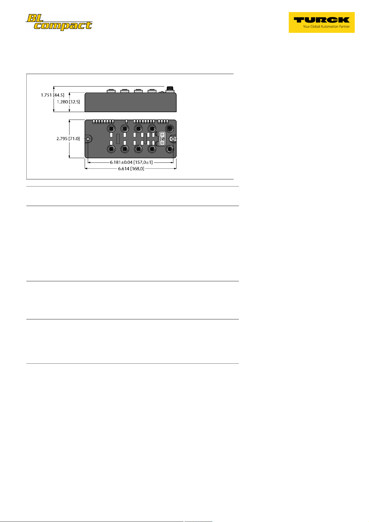
Dimensions (W x L x H) 71 x 168 x 32.5mm
Operating temperature -40...+70 ºC
Storage temperature -40...+85 ºC
Relative humidity 15 to 95% (non-condensing)
Protection class IP67
IP69K
Housing material Glass-filled nylon, nickel plated brass connectors
Housing color Black
Window material Lexan
Material screw Nickel-plated brass
Material label Polyester with polycarbonate overlay
Ground label material Nickel plated brass
Weight 550 ± 20 g
Mounting 2 × 5.4 mm diameter holes, 1.7 Nm torque
Edition • Rev. A • 2019-02-04T21:34:20+01:00
1 / 4 TURCK Inc.
BL compact™ fieldbus station for DeviceNet™
8 Analog Inputs for Thermocouple Elements
BLCDN-8M12L-4AI-TC-4AI-TC
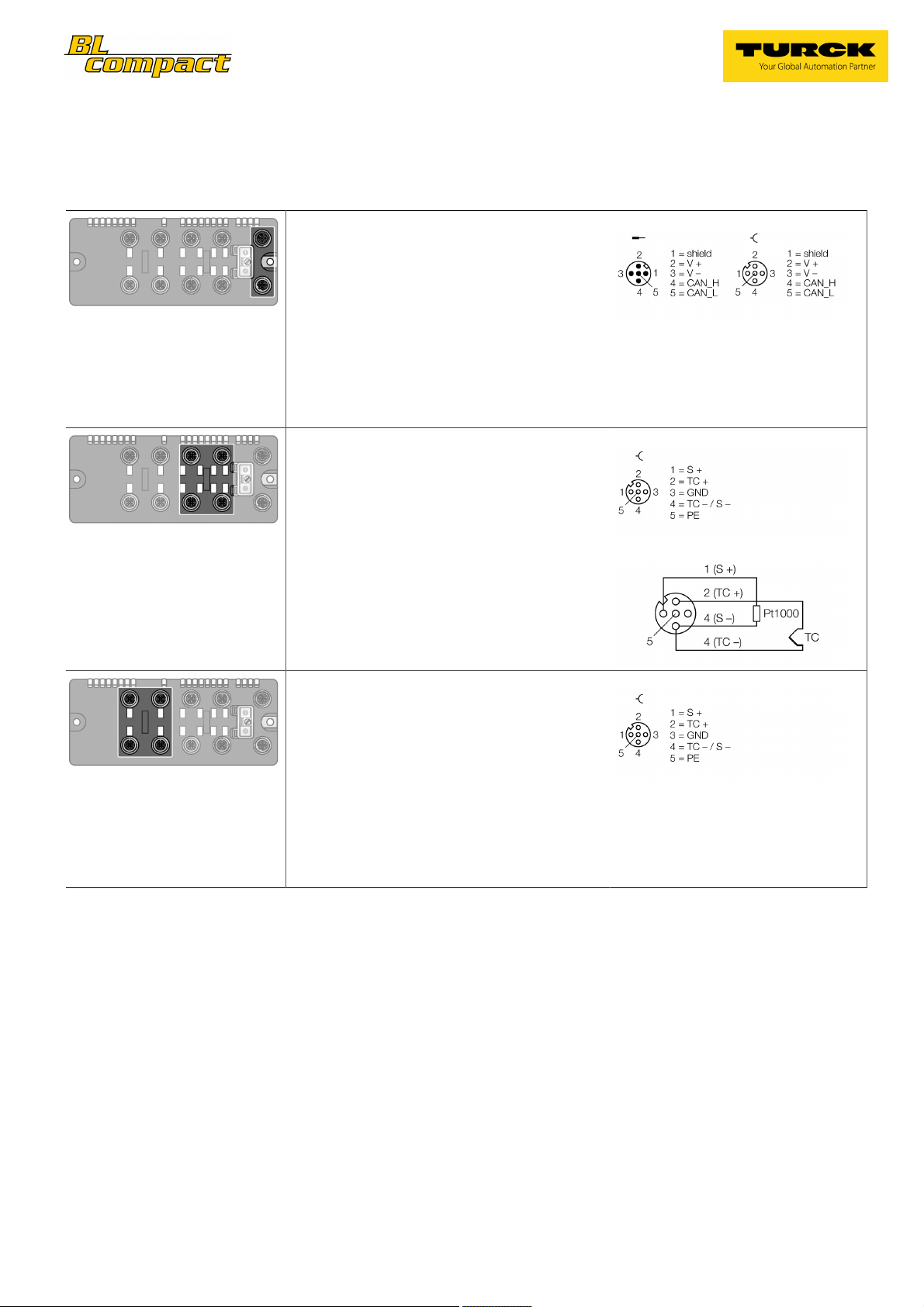
Pinning and wiring diagram
DeviceNet™
Fieldbus cable (example): RSC RKC 572-2M ident-no. U0323 or
RSC-RKC572-2M ident-no. 6603629
Pin Assignment
Slot 1: Thermocouple Inputs
TC compensating connector BL67-WAS5-THERMO ident-no.
6827197
Slot 2: Thermocouple Inputs
See slot 1
Pin Assignment
Wiring Diagram
Pin Assignment
Edition • Rev. A • 2019-02-04T21:34:20+01:00
2 / 4 TURCK Inc.

BL compact™ fieldbus station for DeviceNet™
8 Analog Inputs for Thermocouple Elements
BLCDN-8M12L-4AI-TC-4AI-TC
Station LED status
LED Color Status Description
IOs OFF No power
RED ON Low power or station error
RED FLASHING (1 Hz) I/O module configuration error
RED FLASHING (4 Hz) No I/O module bus communication
GREEN ON Station ok
GREEN FLASHING Force mode active
MNS
GREEN ON Connection established
GREEN FLASHING (1 Hz) No connection established, device OK
RED ON Duplicate MAC-ID
RED FLASHING Connection time out
IO
I/O LED status slot 1
LED Color Status Description
D1 * OFF No diagnostics active
AI channel
0 / 1
* D1 LED also indicates gateway diagnostics
I/O LED status slot 2
LED Color Status Description
D2 * OFF No diagnostics active
* D2 LED also indicates gateway diagnostics
GREEN ON I/O active
GREEN FLASHING (1 Hz) One or more I/O in Idle State
RED ON One or more I/O error
RED FLASHING One or more I/O in Faulted State
RED ON Station error/ module bus communication failure
RED FLASHING (0.5Hz) Diagnostics active (Slot 1)
AI channel
2 / 3
RED ON Station error/ module bus communication failure
RED FLASHING (0.5Hz) Diagnostics active (Slot 2)
OFF No connection
Not connected
Edition • Rev. A • 2019-02-04T21:34:20+01:00
3 / 4 TURCK Inc.

BL compact™ fieldbus station for DeviceNet™
8 Analog Inputs for Thermocouple Elements
BLCDN-8M12L-4AI-TC-4AI-TC
I/O & Diagnostic Data Map
INPUT BYTE Bit 7 Bit 6 Bit 5 Bit 4 Bit 3 Bit 2 Bit 1 Bit 0
0
1
2
3
0
1
2
3
Slot X* (ref.
Byte 16)
* The scheduled diagnostic information changes every 125 ms between Slot 1 and Slot 2, if both slots send active diagnostics.
0 AI 10 LSBAI 1
1 AI 10 MSB
2 AI 11 LSBAI 1
3 AI 11 MSB
4 AI 12 LSBAI 1
5 AI 12 MSB
6 AI 13 LSBAI 1
7 AI 13 MSB
8 AI 20 LSBAI 2
9 AI 20 MSB
10 AI 21 LSBAI 2
11 AI 21 MSB
12 AI 22 LSBAI 2
13 AI 22 MSB
14 AI 23 LSBAI 2
15 AI 23 MSB
16 Module number reporting diagnostic dataDiagnostics
17 Replace Sta-
tion
- Diagnostics
Active
- - - - -
18 - - - - - - Open Circuit
AI X
0
19 - - - - - - Open Circuit
AI X
1
20 - - - - - - Open Circuit
AI X
2
21 - - - - - - Open Circuit
AI X
3
Range Error
AI X
Range Error
AI X
Range Error
AI X
Range Error
AI X
0
1
2
3
Edition • Rev. A • 2019-02-04T21:34:20+01:00
4 / 4 TURCK Inc.
 Loading...