

Magnetic Field Sensor
ID Number: 100001904
for pneumatic cylinders
BIM-UNC-AP6X
Type designation BIM-UNC-AP6X
Ident no. 100001904
■ For SMC C-groove cylinders without
mounting accessories
■ One-hand mounting possible
■ Stable mounting
■ Magneto-resistive sensor
■ DC 3-wire, 11…30 VDC
■ NO contact, PNP output
■ Cable connection
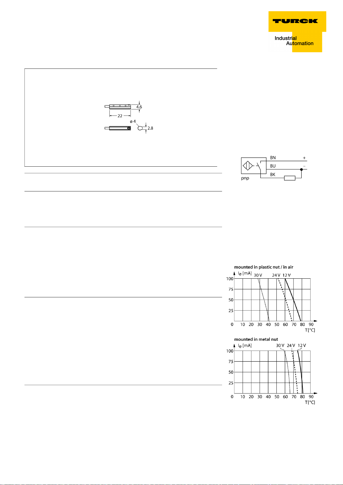
Wiring Diagram
Pass speed
Repeatability
Temperature drift
Hysteresis
Ambient temperature -25…+70 °C
Operating voltage 11…30 VDC
Residual ripple
DC rated operational current
No-load current I
Residual current
Isolation test voltage
Short-circuit protection yes/ Cyclic
Voltage drop at I
Wire breakage/Reverse polarity protection yes/ Complete
Output function 3-wire, NO contact, PNP
Switching frequency 0.3 kHz
Design Rectangular
Dimensions 22.1 x 4.6 mm
Housing material Plastic, PP-GF20
Active area material plastic, PP-GF20
Tightening torque fixing screw 0.1 Nm
Electrical connection Cable
Cable quality 2 mm, Gray, TPU, 2m
Cable cross section
Vibration resistance 55 Hz (1 mm)
Shock resistance 30 g (11 ms)
Protection class IP67
MTTF 2283 years acc. to SN 29500 (Ed. 99) 40 °C
Mounting on the following profiles .
Cylindrical design
0
e
ð 3 m/s
ï ± 0.1 mm
ð 0.1 mm
ð 1 mm
ð 10 % U
ss
ð 100 mA
ð 15 mA
ð 0.1 mA
ð 0.5 kV
ð 1.8 V
3 x 0.08 mm
M
2
Functional principle
Magnetic field sensors are activated by magnetic fields and are used, in particular, for the
detection of the piston position in pneumatic
cylinders. As magnetic fields can permeate
non-magnetizable metals, they detect a permanent magnet attached to the piston through
the aluminium cylinder wall.
Derating Curve
Switching state LED yellow
Included in delivery Cable clip
Edition • 2018-01-19T08:30:36+01:00
1 / 2 Hans Turck GmbH & Co.KG ñ D-45472 Mülheim an der Ruhr ñ Witzlebenstraße 7 ñ Tel. 0208 4952-0 ñ Fax 0208 4952-264 ñ more@turck.com ñ www.turck.com
Magnetic Field Sensor
for pneumatic cylinders
BIM-UNC-AP6X
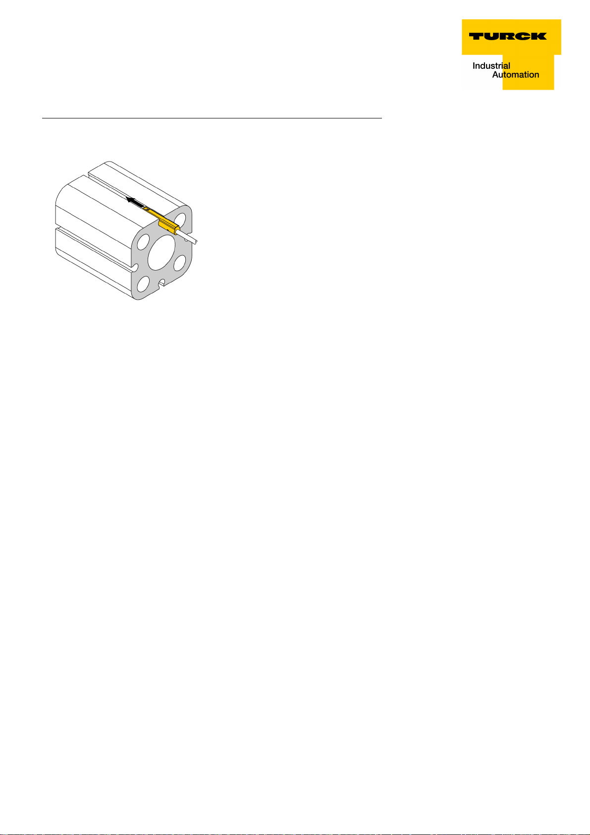
Mounting instructions/Description Mounting instructions
The sensor is mounted in the groove from the side.
If the screw is turned clockwise, it moves out of the
thread and pushes the sensor upwards towards the
cylinder. This fixes the sensor in place. A quarter turn
of the screw with a slotted screwdriver is sufficient to
fasten the sensor so that it doesn't vibrate. A tightening
torque of 0.1 Nm is sufficient for safe mounting without
damaging the cylinder. A cable clip is included in the
scope of delivery. It enables smooth cable routing in the
groove and ensures that the cable is fastened as se-
curely as possible. The corresponding accessories for
mounting on other cylindrical housings must be ordered
separately.
Edition • 2018-01-19T08:30:36+01:00
2 / 2 Hans Turck GmbH & Co.KG ñ D-45472 Mülheim an der Ruhr ñ Witzlebenstraße 7 ñ Tel. 0208 4952-0 ñ Fax 0208 4952-264 ñ more@turck.com ñ www.turck.com
 Loading...