

Magnetic Field Sensor
for pneumatic cylinders
BIM-NST-Y1X-H1141 W/O BKT
■ ATEX category II 2 G, Ex zone 1
■ ATEX category II 1 D, Ex zone 20
■ SIL2 (Low Demand Mode) acc. to IEC
61508, PL c acc. to ISO 13849-1 at HFT0
■ SIL3 (All Demand Mode) acc. to IEC
61508, PL e acc. to ISO 13849-1 with redundant configuration HFT1
■ Plastic, PA12-GF30
■ Magnetic-inductive sensor
■ DC 2-wire, nom. 8.2 VDC
■ Output acc. to DIN EN 60947-5-6 (NA-
MUR)
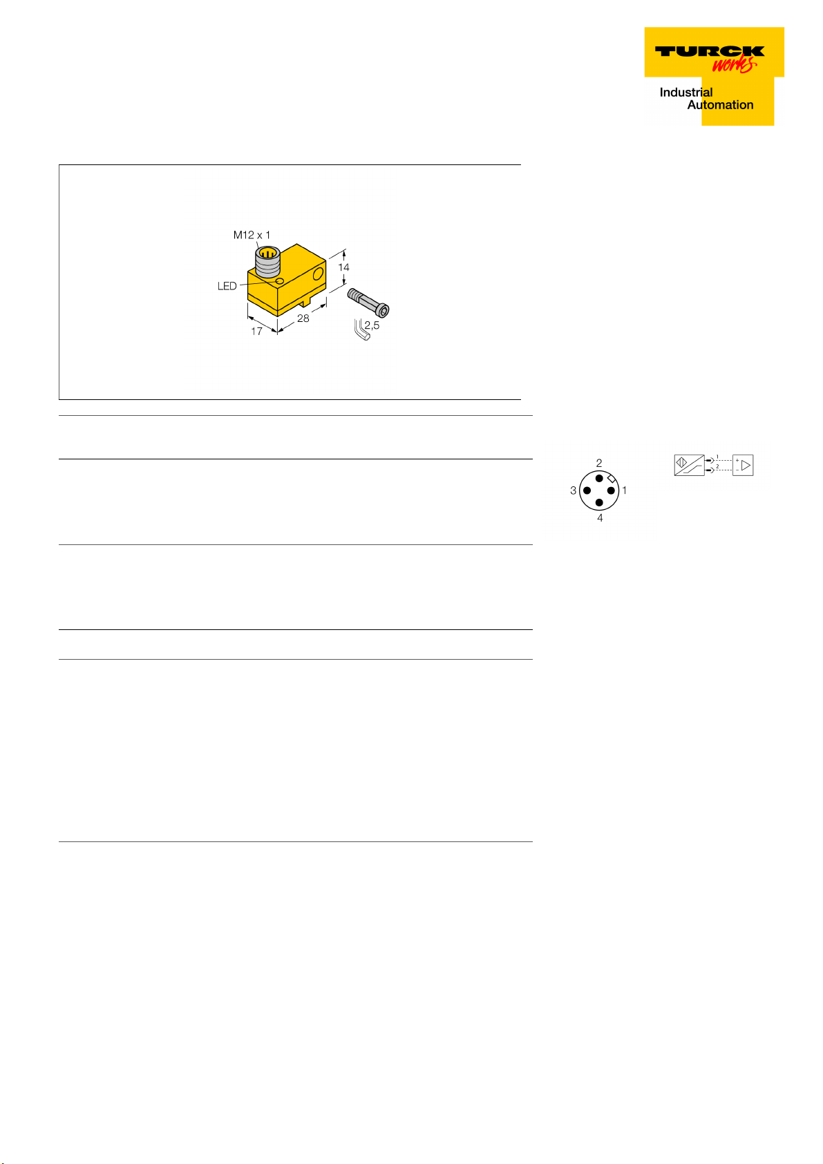
■ Male connector M12 x 1
Type designation BIM-NST-Y1X-H1141 W/O BKT
Ident-No. 1058600
Pass speed
Repeatability
Temperature drift
Hysteresis
Ambient temperature -25…+70 °C
Output function 2-wire, NAMUR
Switching frequency 1 kHz
Voltage Nom. 8.2 VDC
Current consumption non-actuated
Actuated current consumption
Approval acc. to KEMA 02 ATEX 1090X
Design Rectangular,NST
Dimensions 28 x 17 x 14 mm
Housing material Plastic, PA12-GF30
Active area material Plastic, PA12-GF30
Electrical connection Connector, M12 × 1
Vibration resistance 55 Hz (1 mm)
Shock resistance 30 g (11 ms)
Protection class IP67
MTTF 6198 years acc. to SN 29500 (Ed. 99) 40 °C
Packaging unit 1
Mounting on the following profiles .
Cylindrical design
ð 10 m/s
ð ± 0.1 mm
ð 0.1 mm
ð 1 mm
ð 1.2 mA
ï 2.1 mA
N K L H I
Wiring Diagram
Functional principle
Magnetic field sensors are activated by magnetic fields and are especially suited for piston position detection in pneumatic cylinders.
Based on the fact that magnetic fields can
permeate non-magnetizable metals, it is possible to detect a permanent magnet attached
to the piston through the aluminium wall of the
cylinder.
Switching state LED,Yellow
Included in delivery 1 x screw M3x20, 1 x tension bolt, 1 x spring washer
Edition • 2018-03-28T21:02:42+02:00
1 / 5 TURCK Inc.

Magnetic Field Sensor
for pneumatic cylinders
BIM-NST-Y1X-H1141 W/O BKT
Edition • 2018-03-28T21:02:42+02:00
2 / 5 TURCK Inc.

Magnetic Field Sensor
for pneumatic cylinders
BIM-NST-Y1X-H1141 W/O BKT
Accessories
Type code Ident-No. Description
IMC-DI-22EX-
PNO/24VDC
7560003 2-channel isolating switching amplifier with M12x1 males,
for peripheral use, IP67, zones 2/22, input circuits II(1) Ex ia,
PNP transistor output NO
IMX12-DI01-2S-2T-0/
24VDC
KLN-3 CLAMP 6970504
SMC-325 6970503
7580020 Isolating switching amplifier, 2-channel; SIL2 acc. to IEC
61508; Ex-proof version; 2 transistor outputs; input Namur
signal; ON/OFF switchable monitoring of wire-break and
short-circuit; toggle between NO/NC mode; signal doubling;
removable screw terminals; 12.5 mm wide; 24 VDC power
supply
Mounting on K Dovetail groove cylinders or N T-groove
cylinders; clamping width 5.2…13.5 mm; material: Anodized
aluminium
Mounting on K SMC cylinders; clamping width 4 mm; mate-
rial: Anodized aluminium
KLF-1 6970401
Edition • 2018-03-28T21:02:42+02:00
3 / 5 TURCK Inc.
Mounting on H external dovetail grooves; for all cylinder di-
ameters, material: Anodized aluminium

Magnetic Field Sensor
for pneumatic cylinders
BIM-NST-Y1X-H1141 W/O BKT
Accessories
Type code Ident-No. Description
KLF-2 6970402
Mounting on I external dovetail grooves (IMI Norgrem); for
all cylinder diameters, material: Anodized aluminium
SMC-325 A3106
Mounting on K SMC cylinders; clamping width 4 mm; mate-
rial: Anodized aluminium
Edition • 2018-03-28T21:02:42+02:00
4 / 5 TURCK Inc.

Magnetic Field Sensor
for pneumatic cylinders
BIM-NST-Y1X-H1141 W/O BKT
Operating manual
Intended use
This device fulfills the directive 2014/34/EC and is suited for use in explosion hazardous areas according to EN 60079-0:2012 + A11 and EN
60079-11:2012.
Further it is suited for use in safety-related systems, including SIL2 as per IEC 61508.
In order to ensure correct operation to the intended purpose it is required to observe the national regulations and directives.
For use in explosion hazardous areas conform to classification
II 2 G and II 1 D (Group II, Category 2 G, electrical equipment for gaseous atmospheres and category 1 D, electrical equipment for dust atmospheres).
Marking (see device or technical data sheet)
É II 2 G and Ex ia IIC T6 Gb and É II 1 D Ex ia IIIC T95 °C Da acc. to EN 60079-0, -11
Local admissible ambient temperature
-25…+70 °C
Installation/Commissioning
These devices may only be installed, connected and operated by trained and qualified staff. Qualified staff must have knowledge of protection
classes, directives and regulations concerning electrical equipment designed for use in explosion hazardous areas.
Please verify that the classification and the marking on the device comply with the actual application conditions.
This device is only suited for connection to approved Exi circuits according to EN 60079-0 and EN 60079-11. Please observe the maximum admissible electrical values.
After connection to other circuits the sensor may no longer be used in Exi installations. When interconnected to (associated) electrical equipment, it is required to perform the "Proof of intrinsic safety" (EN60079-14).
Attention! When used in safety systems, all content of the security manual must be observed.
Installation and mounting instructions
Avoid static charging of cables and plastic devices. Please only clean the device with a damp cloth. Do not install the device in a dust flow and
avoid build-up of dust deposits on the device.
If the devices and the cable could be subject to mechanical damage, they must be protected accordingly. They must also be shielded against
strong electro-magnetic fields.
The pin configuration and the electrical specifications can be taken from the device marking or the technical data sheet.
In order to avoid contamination of the device, please remove possible blanking plugs of the cable glands or connectors only shortly before inserting the cable or opening the cable socket.
Service/Maintenance
Repairs are not possible. The approval expires if the device is repaired or modified by a person other than the manufacturer. The most important
data from the approval are listed.
Edition • 2018-03-28T21:02:42+02:00
5 / 5 TURCK Inc.
 Loading...