

Magnetic Field Sensor
Magnetic-inductive Proximity Sensor
BIM-EG08-Y1X
Type designation BIM-EG08-Y1X
Ident-No. 1074000
■ ATEX category II 1 G, Ex zone 0
■ ATEX category II 1 D, Ex zone 20
■ SIL2 (Low Demand Mode) acc. to IEC
61508, PL c acc. to ISO 13849-1 at HFT0
■ SIL3 (All Demand Mode) acc. to IEC
61508, PL e acc. to ISO 13849-1 with redundant configuration HFT1
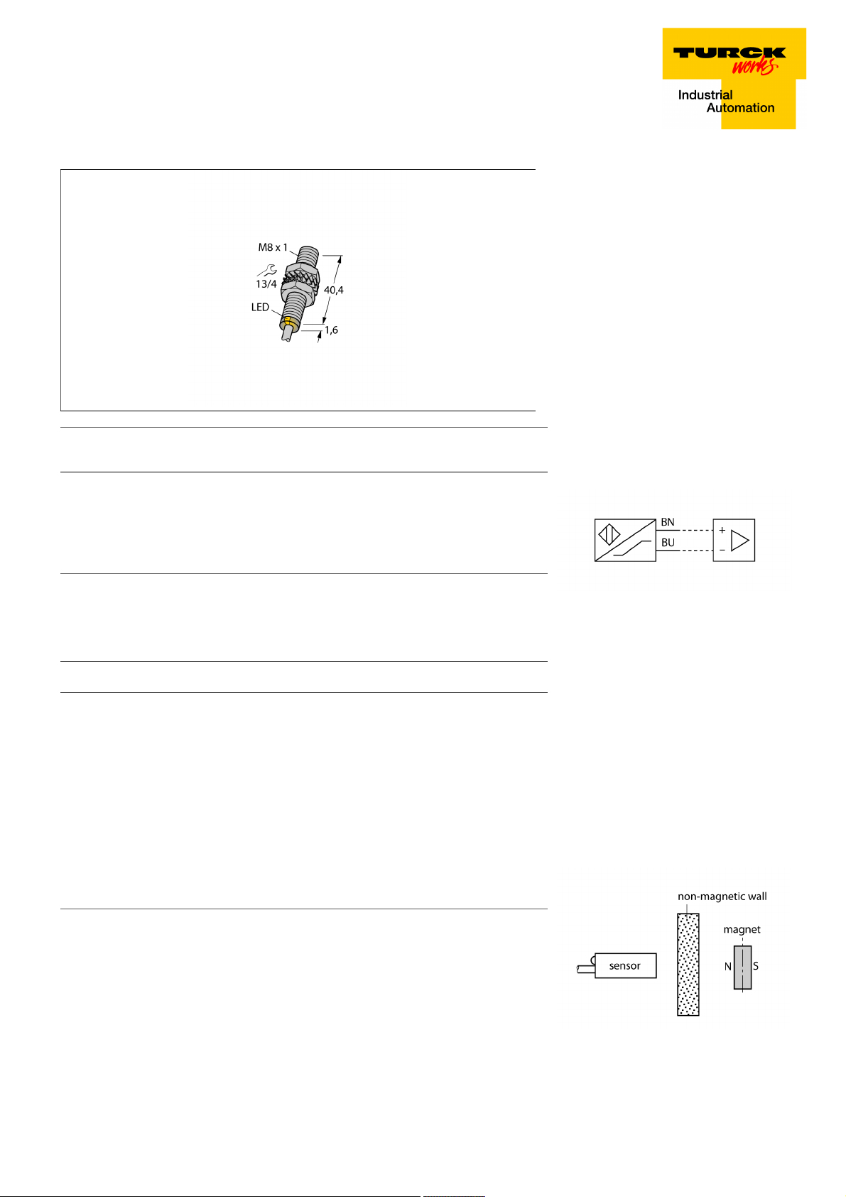
■ M8 × 1 threaded barrel
■ Stainless steel, 1.4427 SO
■ Rated operating distance 78 mm with
DMR31-15-5 magnet
■ DC 2-wire, nom. 8.2 VDC
■ Output acc. to DIN EN 60947-5-6 (NA-
MUR)
■ Cable connection
Rated switching distance Sn 78 mm
In conjunction with magnet DMR31-15-5
Repeat accuracy
Temperature drift
Hysteresis 1…10 %
Ambient temperature -25…+70 °C
Output function 2-wire, NAMUR
Switching frequency 1 kHz
Voltage Nom. 8.2 VDC
Current consumption non-actuated
Actuated current consumption
Approval acc. to KEMA 02 ATEX 1090X
Design Threaded barrel,M8 × 1
Dimensions 41.6 mm
Housing material Stainless steel, 1.4427 SO
Active area material Plastic, PA12-GF30
End cap Plastic, PP
Max. tightening torque housing nut 5 Nm
Electrical connection Cable
Cable quality 4mm, Blue, Lif9YYW, PVC, 2
Cable cross section
Vibration resistance 55 Hz (1 mm)
Shock resistance 30 g (11 ms)
Protection class IP67
MTTF 6198 years acc. to SN 29500 (Ed. 99) 40 °C
Packaging unit 1
ð 0.3 % of full scale
ð ± 10 %
ð 1.2 mA
ï 2.1 mA
2 x 0.25 mm
2
Wiring Diagram
Functional principle
Magnetic inductive proximity sensors are actuated by magnetic fields and are thus capable of detecting permanent magnets through
non-ferromagnetic materials (e.g. wood, plastic, non-ferrous metals, aluminium, stainless
steel).
Thus it is possible to achieve large switching
distances even with smaller housing styles.
In combination with the actuation magnet
DMR31-15-5 TURCK sensors feature a relatively high switching distance. Thus there are
multiple detection possibilities, particularly if
the mounting space is limited or other difficult
sensing conditions prevail.
Switching state LED,Yellow
Edition • 2018-03-28T20:27:10+02:00
1 / 5 TURCK Inc.

Magnetic Field Sensor
Magnetic-inductive Proximity Sensor
BIM-EG08-Y1X
Diameter active area B Ø 8 mm
Edition • 2018-03-28T20:27:10+02:00
2 / 5 TURCK Inc.
Magnetic Field Sensor
Magnetic-inductive Proximity Sensor
BIM-EG08-Y1X
Accessories
Type code Ident-No. Description
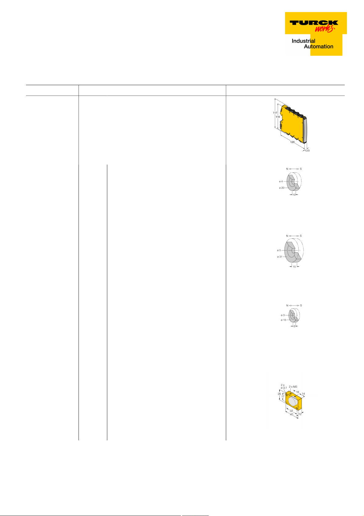
IMX12-DI01-2S-2T-0/
24VDC
DMR20-10-4 6900214 Actuation magnet; Ø 20 mm (Ø 4 mm), h: 10 mm; sensing
7580020 Isolating switching amplifier, 2-channel; SIL2 acc. to IEC
61508; Ex-proof version; 2 transistor outputs; input Namur
signal; ON/OFF switchable monitoring of wire-break and
short-circuit; toggle between NO/NC mode; signal doubling;
removable screw terminals; 12.5 mm wide; 24 VDC power
supply
range 59 mm on BIM-(E)M12 sensors resp. 50 mm on BIM-
EG08 sensors; in combination with Q25L: Recommended
distance between sensor and magnet: 3 … 4 mm
DMR31-15-5 6900215 Actuation magnet, Ø 31 mm (Ø 5 mm), h: 15 mm; sensing
range 90 mm on BIM-(E)M12 sensors resp. 78 mm on BIM-
EG08 sensors; in combination with Q25L: Recommended
distance between sensor and magnet: 3 … 5 mm
DMR15-6-3 6900216 Actuation magnet, Ø 15 mm (Ø 3 mm), h: 6 mm; sensing
range 36 mm on BIM-(E)M12 sensors resp. 32 mm on BIM-
EG08 sensors; in combination with Q25L: Recommended
distance between sensor and magnet: 3 … 4 mm
DM-Q12 6900367 Actuation magnet; rectangular, plastic; attainable switching
distance 58 mm on BIM-(E)M12 sensors resp. 49 mm on
BIM-EG08 sensors; in combination with Q25L linear position
sensors: recommended distance between the sensor and
magnet: 3…5 mm
Edition • 2018-03-28T20:27:10+02:00
3 / 5 TURCK Inc.

Magnetic Field Sensor
Magnetic-inductive Proximity Sensor
BIM-EG08-Y1X
Accessories
Type code Ident-No. Description
BSS-08 6901322 Mounting bracket for smooth and threaded barrel devices;
material: Polypropylene
MW-08 6945008 Mounting bracket for threaded barrel devices; material: Stain-
less steel A2 1.4301 (AISI 304)
Edition • 2018-03-28T20:27:10+02:00
4 / 5 TURCK Inc.

Magnetic Field Sensor
Magnetic-inductive Proximity Sensor
BIM-EG08-Y1X
Operating manual
Intended use
This device fulfills the directive 2014/34/EC and is suited for use in explosion hazardous areas according to EN 60079-0:2012 + A11 and EN
60079-11:2012.
Further it is suited for use in safety-related systems, including SIL2 as per IEC 61508.
In order to ensure correct operation to the intended purpose it is required to observe the national regulations and directives.
For use in explosion hazardous areas conform to classification
II 1 G and II 1 D (Group II, Category 1 G, electrical equipment for gaseous atmospheres and category 1 D, electrical equipment for dust atmospheres).
Marking (see device or technical data sheet)
É II 1 G and Ex ia IIC T6 Ga and É II 1 D Ex ia IIIC T95 °C Da acc. to EN 60079-0, -11
Local admissible ambient temperature
-25…+70 °C
Installation/Commissioning
These devices may only be installed, connected and operated by trained and qualified staff. Qualified staff must have knowledge of protection
classes, directives and regulations concerning electrical equipment designed for use in explosion hazardous areas.
Please verify that the classification and the marking on the device comply with the actual application conditions.
This device is only suited for connection to approved Exi circuits according to EN 60079-0 and EN 60079-11. Please observe the maximum admissible electrical values.
After connection to other circuits the sensor may no longer be used in Exi installations. When interconnected to (associated) electrical equipment, it is required to perform the "Proof of intrinsic safety" (EN60079-14).
Attention! When used in safety systems, all content of the security manual must be observed.
Installation and mounting instructions
Avoid static charging of cables and plastic devices. Please only clean the device with a damp cloth. Do not install the device in a dust flow and
avoid build-up of dust deposits on the device.
If the devices and the cable could be subject to mechanical damage, they must be protected accordingly. They must also be shielded against
strong electro-magnetic fields.
The pin configuration and the electrical specifications can be taken from the device marking or the technical data sheet.
Service/Maintenance
Repairs are not possible. The approval expires if the device is repaired or modified by a person other than the manufacturer. The most important
data from the approval are listed.
Edition • 2018-03-28T20:27:10+02:00
5 / 5 TURCK Inc.
 Loading...