

Inductive sensor
BI5-G18-Y1X
■ ATEX category II 1 G, Ex zone 0
■ ATEX category II 1 D, Ex zone 20
■ SIL2 (Low Demand Mode) acc. to IEC
61508, PL c acc. to ISO 13849-1 at HFT0
■ SIL3 (All Demand Mode) acc. to IEC
61508, PL e acc. to ISO 13849-1 with redundant configuration HFT1
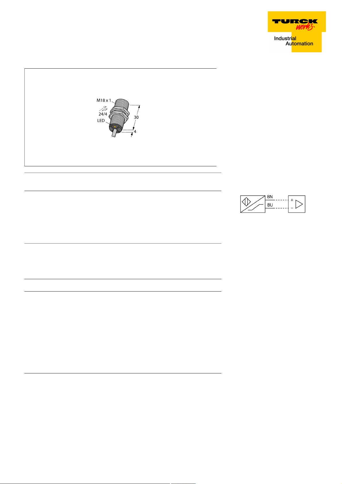
■ Threaded barrel, M18 x 1
■ Chrome-plated brass
■ DC 2-wire, nom. 8.2 VDC
■ Output acc. to DIN EN 60947-5-6 (NA-
MUR)
■ Cable connection
Type designation BI5-G18-Y1X
Ident-No. 40150
Rated switching distance Sn 5 mm
Mounting conditions Flush
Secured operating distance
Correction factors St37 = 1; Al = 0.3; stainless steel = 0.7; Ms = 0.4
Repeat accuracy
Temperature drift
Hysteresis 1…10 %
Ambient temperature -25…+70 °C
Output function 2-wire, NAMUR
Switching frequency 1 kHz
Voltage Nom. 8.2 VDC
Non-actuated current consumption
Actuated current consumption
Approval acc. to KEMA 02 ATEX 1090X
Design Threaded barrel,M18 × 1
Dimensions 34 mm
Housing material Metal, CuZn, Chrome-plated
Active area material Plastic, PA12-GF30
End cap Plastic, EPTR
Max. tightening torque housing nut 25 Nm
Electrical connection Cables
Cable quality 5.2mm, Blue, LifYY, PVC, 2
Cable cross section
Vibration resistance 55 Hz (1 mm)
Shock resistance 30 g (11 ms)
MTTF 6198 years acc. to SN 29500 (Ed. 99) 40 °C
Packaging unit 1
ð (0,81 x Sn) mm
ð 2 % of full scale
ð ± 10 %
ï 2.1 mA
ð 1.2 mA
2 x 0.34 mm
2
Wiring Diagram
Functional principle
Inductive sensors detect metal objects contactless and wear-free. For this, they use a
high-frequency electromagnetic AC field that
interacts with the target. Inductive sensors
generate this field via an RLC circuit with a
ferrite coil.
Switching state LED,Yellow
Edition • 2018-07-09T17:45:33+02:00
1 / 4 TURCK Inc.
Inductive sensor
BI5-G18-Y1X
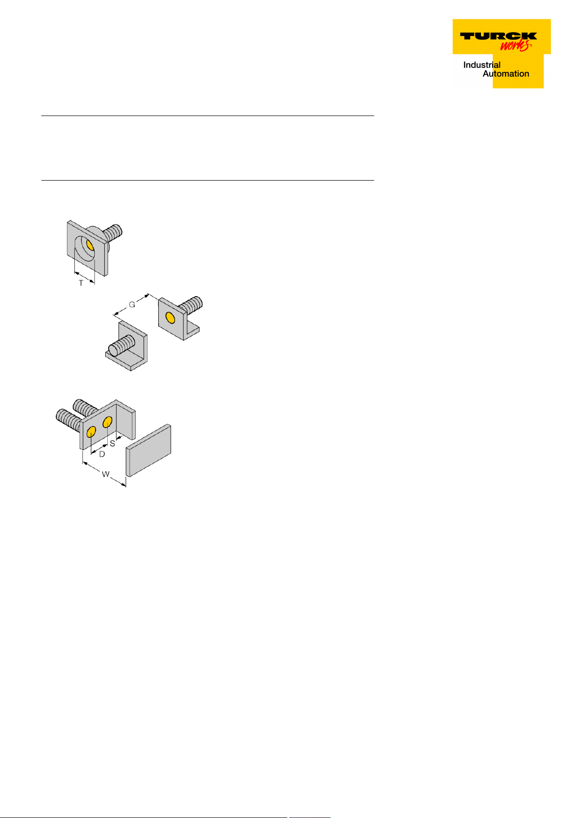
Distance D 2 x B
Distance W 3 x Sn
Distance T 3 x B
Distance S 1.5 x B
Distance G 6 x Sn
Diameter active area B Ø 18 mm
Edition • 2018-07-09T17:45:33+02:00
2 / 4 TURCK Inc.

Inductive sensor
BI5-G18-Y1X
Accessories
Type code Ident-No. Description
MW-18 6945004 Mounting bracket for threaded barrel devices; material: Stain-
less steel A2 1.4301 (AISI 304)
BSS-18 6901320 Mounting bracket for smooth and threaded barrel devices;
material: Polypropylene
IMX12-DI01-2S-2T-0/
24VDC
7580020 Isolating switching amplifier, 2-channel; SIL2 acc. to IEC
61508; Ex-proof version; 2 transistor outputs; input Namur
signal; ON/OFF switchable monitoring of wire-break and
short-circuit; toggle between NO/NC mode; signal doubling;
removable screw terminals; 12.5 mm wide; 24 VDC power
supply
Edition • 2018-07-09T17:45:33+02:00
3 / 4 TURCK Inc.

Inductive sensor
BI5-G18-Y1X
Operating manual
Intended use
This device fulfills the directive 2014/34/EC and is suited for use in explosion hazardous areas according to EN 60079-0:2012 + A11 and EN
60079-11:2012.
Further it is suited for use in safety-related systems, including SIL2 as per IEC 61508.
In order to ensure correct operation to the intended purpose it is required to observe the national regulations and directives.
For use in explosion hazardous areas conform to classification
II 1 G and II 1 D (Group II, Category 1 G, electrical equipment for gaseous atmospheres and category 1 D, electrical equipment for dust atmospheres).
Marking (see device or technical data sheet)
É II 1 G and Ex ia IIC T6 Ga acc. to EN60079-0 and -26 and É II 1 D Ex ia IIIC T115°C Da acc. to EN60079-0
Local admissible ambient temperature
-25…+70 °C
Installation/Commissioning
These devices may only be installed, connected and operated by trained and qualified staff. Qualified staff must have knowledge of protection
classes, directives and regulations concerning electrical equipment designed for use in explosion hazardous areas.
Please verify that the classification and the marking on the device comply with the actual application conditions.
This device is only suited for connection to approved Exi circuits according to EN 60079-0 and EN 60079-11. Please observe the maximum admissible electrical values.
After connection to other circuits the sensor may no longer be used in Exi installations. When interconnected to (associated) electrical equipment, it is required to perform the "Proof of intrinsic safety" (EN60079-14).
Attention! When used in safety systems, all content of the security manual must be observed.
Installation and mounting instructions
Avoid static charging of cables and plastic devices. Please only clean the device with a damp cloth. Do not install the device in a dust flow and
avoid build-up of dust deposits on the device.
If the devices and the cable could be subject to mechanical damage, they must be protected accordingly. They must also be shielded against
strong electro-magnetic fields.
The pin configuration and the electrical specifications can be taken from the device marking or the technical data sheet.
Service/Maintenance
Repairs are not possible. The approval expires if the device is repaired or modified by a person other than the manufacturer. The most important
data from the approval are listed.
Edition • 2018-07-09T17:45:33+02:00
4 / 4 TURCK Inc.
 Loading...