

turck BI6U-MT12, BI20U-M30, BI10U-M18, BI10U-MT18, BI20U-MT30 Operating Instructions Manual
...Page 1

Your Global Automation Partner
Operating Instructions
Inductive Sensors
uprox®
with IO-Link Interface
Page 2

2
Hans Turck GmbH & Co. KG | T +49 208 4952-0 | F +49 208 4952-264 | more@turck.com | www.turck.com
Contents
Page 3

3
2016/08
uprox® Sensors with IO-Link Interface
1 About this manual 5
1.1 Target groups 5
1.2 Explanation of symbols 5
1.3 Other documents 5
1.4 Feedback about these instructions 6
2 Notes on the product 7
2.1 Product identication 7
2.2 Scope of delivery 7
2.3 Legal requirements 8
2.4 Manufacturer and service 8
3 For your safety 9
3.1 Intended use 9
3.2 Obvious misuse 9
3.3 General safety instructions 9
4 Product description 10
4.1 Device overview 10
4.1.1 Indication elements 11
4.2 Properties and features 11
4.2.1 Properties and features – Rectangular design 11
4.3 Operating principle 11
4.4 Functions and operating modes 11
4.4.1 Sensor functions 11
4.4.2 Settable properties 13
4.4.3 Standard I/O mode (SIO mode) 16
4.5 Technical accessories 16
5 Mounting 17
5.1 Mounting cylindrical devices 17
5.1.1 Mounting cylindrical devices with a half-shell clamp 18
5.2 Mounting rectangular devices 19
5.2.1 Positioning the active face (Ni50U-QV40…) 21
5.2.2 Positioning the active face (NI50U-CK40…) 22
6 Connection 23
6.1 Wiring diagram 23
7 Commissioning 23
7.1 Setting IO-Link mode 23
7.2 Setting up SIO mode 23
8 Operation 24
8.1 LEDs 24
8.2 Operating devices in IO-Link mode 24
8.3 Operating devices in SIO mode 24
Contents
Page 4

4
Hans Turck GmbH & Co. KG | T +49 208 4952-0 | F +49 208 4952-264 | more@turck.com | www.turck.com
9 Setting 24
9.1 Setting via IO-Link 24
9.1.1 IO-Link parameters 25
9.1.2 Parameter transfer with IO-Link call function block 25
9.1.3 Process data 25
9.2 Setting in SIO mode 26
9.2.1 Setting the device before initial commissioning 26
9.2.2 Setting devices after initial commissioning 26
10 Troubleshooting 26
11 Maintenance 26
12 Repair 26
12.1 Returning devices 26
13 Decommissioning 27
14 Disposal 27
15 Technical data 28
15.1 Technical data – Bi…U-M… 28
15.2 Technical data – BI…U-MT… 29
15.3 Technical data – Ni50U-… 30
Page 5
5
2016/08
uprox® Sensors with IO-Link Interface
1 About this manual
This manual describes the setup, the functions and use of the product and helps you to operate
the product for its intended use. Read these instructions carefully prior to using the product.
This will prevent the risk of personal injury and damage to property. Keep these instructions
safe during the service life of the product. If the product is passed on, pass on these instructions
as well.
1.1 Target groups
This document is written for specially trained personnel, and must be read carefully by anyone
who is charged with the mounting, commissioning, operation, maintenance, disassembly or
disposal of the device.
1.2 Explanation of symbols
The following symbols are used in these instructions:
DANGER
DANGER indicates an immediate hazardous situation, which, if not avoided, will result
in death or serious injury.
WARNING
WARNING indicates a possible hazardous situation with the risk of death or serious
injury if it is not prevented.
NOTICE
NOTICE indicates a situation that may cause possible damage to property if it is not
prevented.
NOTE
NOTE indicates tips, recommendations and important information. The notes simplify
work, contain information on particular operating steps and help to avoid additional
work resulting from incorrect procedures.
MANDATORY ACTION
This symbol denotes actions that the user must carry out.
RESULT OF ACTION
This symbol denotes the relevant results of actions and procedures.
1.3 Other documents
Besides this document the following material can be found on the Internet at www.turck.com:
■
Data sheet of the respective device
■
IODD file
■
IO-Link parameter manual
All the required Turck software components and the IODD can be downloaded via the Turck
Software Manager. The Turck Software Manager can be downloaded free of charge from
www.turck.com.
Page 6

6
Hans Turck GmbH & Co. KG | T +49 208 4952-0 | F +49 208 4952-264 | more@turck.com | www.turck.com
About this manual
1.4 Feedback about these instructions
We make every effort to ensure that these instructions are as informative and as clear as possible. If you have any suggestions for improving the design or if some information is missing in
the document, please send your suggestions to techdoc@turck.com.
Page 7
7
2016/08
uprox® Sensors with IO-Link Interface
2 Notes on the product
2.1 Product identication
2.2 Scope of delivery
The following are included in the scope of delivery:
■
Sensor
■
2 fixing nuts (with threaded barrel devices)
■
2 lock washers (with M12 and Bi…U-MT… design)
■
Mounting bracket BS4-CK40 (with Ni…U-CK40…)
■
Mounting block and mounting bracket (with Ni…U-QV40…)
■
Quick Start Guide
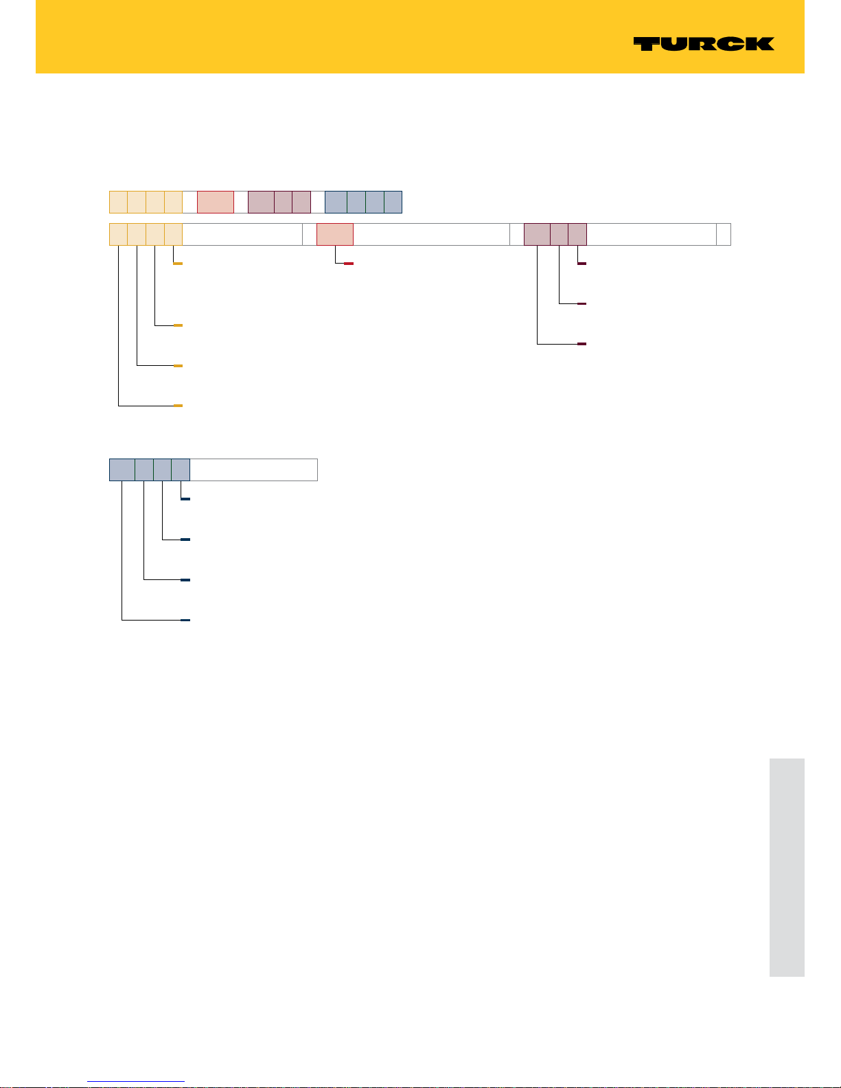
B i 10 U – M18 – IOL 6 X2 – H1141
B i 10 U
Functional principle
–
Special functions
U uprox® or uprox®+ or
uprox®3
Faktor 1 sensors
Rated switching distance
… Switching distance
Functional principle
i Inductive
Installation
B Flush
N Non-flush
M18
Design
–
Housing
M Threaded barrel, brass,
Ø in [mm]
MT Threaded barrel, brass,
PTFE coated, Ø in [mm]
CK40 Rectangular, variable orientation
of active face in 5 directions
QV40 Rectangular, variable orientation
of active face in 5 directions
IOL 6 X2
Electrical version
–
Indication
X2 Multicolor LED
Voltage range
6 10…30 VDC
Technology
IOL IO-Link
H1141
Electrical connection:
Connector
Assignment
1 Standard assignment
Number of contacts
4 Number of contacts
Connector design
1 Straight
Connector design
H1 Receptacle, M12 x 1
Page 8

8
Hans Turck GmbH & Co. KG | T +49 208 4952-0 | F +49 208 4952-264 | more@turck.com | www.turck.com
Notes on the product
2.3 Legal requirements
The device is subject to the following EC directives:
■
2014/35/EU (low voltage)
■
2014/30/EU (electromagnetic compatibility)
2.4 Manufacturer and service
Turck supports you in your projects – from the initial analysis right through to the commissioning of your application. The Turck product database offers you several software tools for programming, configuring or commissioning, as well as data sheets and CAD files in many export
formats. You can access the Product Database directly via the following address:
www.turck.de/products
For further inquiries in Germany contact the Sales and Service Team on:
Sales: +49 208 4952-380
Technical: +49 208 4952-390
For overseas inquiries contact your national Turck representative.
Hans Turck GmbH & Co. KG
Witzlebenstraße 7
45472 Mülheim an der Ruhr
Germany
Page 9

9
2016/08
uprox® Sensors with IO-Link Interface
3 For your safety
The product is designed according to state of the art technology. Residual hazards, however,
still exist. Observe the following warnings and safety regulations in order to prevent danger to
persons and property. Turck accepts no liability for damage caused by failure to observe these
warnings and safety instructions.
3.1 Intended use
The devices are designed for installation in large-scale industrial plants and equipment and for
use in industrial automation applications.
The inductive sensors of the uprox® series enable the contactless and wear-free detection of
metallic objects. The factor 1 sensors have no reduction factor; the switching distance is the
same for all metals. The sensors are not susceptible to interference from strong magnetic fields.
The devices can be operated and set with IO-Link masters compliant with specification 1.1 via
an IO-Link interface. Process and diagnostics data can be exchanged during operation via IOLink with the higher controller level.
The devices must only be used as described in these instructions. Any other use is not in accordance with the intended use; Turck accepts no liability for any resulting damage.
3.2 Obvious misuse
■
The devices are not safety components and must not be used for the protection of persons or
property.
■
The listed switching distances are based on a standard target as specified in EN 609475-2:2012. Different targets (especially small targets) may cause changes in the switching
behavior.
3.3 General safety instructions
■
The device must only be fitted, installed, operated, parameterized and maintained by trained
and qualified personnel.
■
Only use the device in compliance with the applicable national and international regulations,
standards and laws.
Page 10
10
Hans Turck GmbH & Co. KG | T +49 208 4952-0 | F +49 208 4952-264 | more@turck.com | www.turck.com
Product description
4 Product description
The cylindrical devices are provided with a metal housing with an M12, M18 or M30 male
thread with an LCP front cap. Variants with a PTFE-coated housing and PTFE-coated front cap
are also available. The active face can be installed flush with the surrounding area.
The rectangular devices are provided with a plastic housing. The active face of the NI…U-QV40
and NI…U-CK40 devices can be set in 5 positions. The active face can be installed flush, partially
flush or non-flush with the surrounding mounting area (see chapt. 5.2).
All devices are provided with a metal-bodied M12 connector (plug) for connecting the sensor
cable. The devices can be set and operated via an IO-Link interface.
The devices are provided with two outputs that can be set independently of each other. Output
1 can be operated either as a switching output or in IO-Link mode, output 2 is designed as a
switching output. The switching distance and other functions can be set for both outputs (see
chapter 4.4).
4.1 Device overview
M12 x 1
LED
17/4
36
52
M12 x 1
9
M12 x 1
36
52
9
LED
24/4
M18 x 1
36/5
46
62
M30 x 1.5
9
M12 x 1
LED
Abb. 1: Dimensions –
M12 design
Abb. 2: Dimensions –
M18 design
Abb. 3: Dimensions –
M30 design
40
40
30
M12 x 1
20
ø 5.3
46
5.3 x 7.3
65
60
LED
Abb. 4: Dimensions –
CK40 design
Abb. 5: Dimensions –
QV40 design
Page 11

11
2016/08
uprox® Sensors with IO-Link Interface
4.1.1 Indication elements
The devices with a cylindrical design are provided with a green and a yellow status LED. The
devices with a rectangular design are provided with 2 green and 2 yellow status LEDs.
4.2 Properties and features
■
Cylindrical and rectangular designs
■
Factor 1 for all metals
■
Degree of protection IP68
■
Resistant to magnetic fields
■
Large switching distance
■
DC 4-wire, 10…30 VDC
■
Male connector, M12 x 1
■
Communication via IO-Link V1.1 or via standard I/O
■
Electrical outputs that can be set independently of each other
■
Switching distance and hysteresis can be set
■
Identification via 32 byte memory
■
Temperature monitoring with settable limits
■
Various timer and diagnostic functions
4.2.1 Properties and features – Rectangular design
■
High luminance corner LEDs
■
Predamping protection based on self-compensation
■
Partially embedded mounting
■
Active face adjustable in 5 positions
4.3 Operating principle
Inductive sensors are used for the contactless and wear-free detection of metallic objects. To
do this, the devices generate an electromagnetic field which interacts with the detected object.
The sensors of the uprox® series have no reduction factor; the switching distance is the same for
all metals.
4.4 Functions and operating modes
The devices can be operated in IO-Link mode or in standard I/O mode (SIO mode). The devices
must be connected to an IO-Link master for operation in IO-Link mode.
IO-Link mode provides bidirectional IO-Link communication between an IO-Link master and
the sensors. For this the devices are integrated in the controller level via an IO-Link master.
The switching signals of the sensors are made available with the process data via the IO-Link
interface. Besides the switching information, diagnostics and identification messages can also
be queried via IO-Link.
Different sensor functions can be configured via the IO-Link interface.
4.4.1 Sensor functions
“One switch point”
The output configuration and the switching behavior can be set for one switch point. Switching
distance (in 20 % increments) and hysteresis are adjustable. With the “One switch point” function, output 2 can be used as a temperature indicator.
Page 12

12
Hans Turck GmbH & Co. KG | T +49 208 4952-0 | F +49 208 4952-264 | more@turck.com | www.turck.com
Product description
“Two switch points”
Switching output 1 and switching output 2 can be used and set to separate switching distances
in 20% increments. A variable hysteresis cannot be set for the “Two switch points” function.
“Low resolution analog mode”
NOTE
The low resolution analog mode can only be used in operation on an IO-Link master.
In low resolution analog mode the switching states are sampled sequentially in 20% increments. This provides distance information which is output via Bit 2…Bit4 of the process data in
binary format.
Switching state indication (binary
coded)
not actuated
S
n
20 % 40 % 60 % 80 % 100 %
1st bit (Bit 4) 0 1 1 0 0 0
2nd bit (Bit 3) 0 0 0 1 1 0
3rd bit (Bit 2) 0 1 0 1 0 1
NOTE
Output 2 can be configured as required or can be used as a temperature indicator. The
maximum switching frequency is reduced to 7 Hz in low resolution analog mode.
“Rotational speed monitor”
The “Rotational speed monitor” enables the device to detect frequency values below and above
a specified frequency window. Upper and lower limit values of the frequency window can be
set between 0 and 30000 pulses per minute. The switching behavior is described in Fig. 6.
1
0
0f
minfmax
30000
Out1
Out2
f [Impulse/min]
Output f < f
minfmin
< f < f
max
f > f
max
Output 1 0 1 1
Output 2 0 1 0
Abb. 6: Output behavior (“Rotational speed monitor” sensor function)
The actual speed can be queried via the acyclic IO-Link parameter data. The tolerance is 3 %.
The switching distance is permanently set to Sn = 60 % in the “Rotational speed monitor” function. The output configuration can be selected as required.
Page 13

13
2016/08
uprox® Sensors with IO-Link Interface
“Pulse divider”
The “Pulse divider” function causes the device to output a signal pulse to the control level after
a specified number of actuation pulses. The number of actuation pulses (divider) can be set
between 1 and 128.
The following values can be set for the minimum duration of the signal pulse:
■
Target object ( 0 ms)
■
1 ms
■
10 ms
■
100 ms
NOTE
In the event of a voltage drop the number of actuation pulses is reset.
The output configuration can be selected as required.
4.4.2 Settable properties
Output conguration – Output 1
The following output configurations can be set for output 1:
■
PNP, NO contact
■
PNP, NC contact
■
NPN, NO contact
■
NPN, NC contact
■
Push-pull, non-inverted
■
Push-pull, inverted
Output conguration – Output 2
The following output configurations can be set for output 2:
■
PNP, NO contact
■
PNP, NC contact
■
NPN, NO contact
■
NPN, NC contact
■
Push-pull, non-inverted
■
Push-pull, inverted
■
Temperature indicator (not available in SIO mode and for the “Two switch points” function)
Switching distance
NOTE
The feature is only available for “One switch point” and “Two switch points” functions.
The switching distance can be set for both outputs to 20 %, 40 %, 60 %, 80 % and 100 % of the
maximum rated switching distance. Different switching distances can be set independently of
each other for output 1 and output 2. The switching distance of output 1 must be greater than
the switching distance of output 2; otherwise the switching distance for switching output 1
is set automatically to 20 % greater than the switching distance for switching output 2. If the
device automatically changes the switching distance for switching output 1, this is indicated by
a request for a new data update.
Page 14

14
Hans Turck GmbH & Co. KG | T +49 208 4952-0 | F +49 208 4952-264 | more@turck.com | www.turck.com
Product description
Switching hysteresis
NOTE
The switching hysteresis setting is only available for the “One switch point” function.
The switching distance hysteresis can be set to the 2 stages “Standard” and “small”.
NOTICE
“Small” hysteresis selected
Uncontrolled changing between the switching states
Set the switching distance and target in the application so that a setting to “small”
hysteresis is possible.
Switch-on delay
NOTE
The switch-on delay can only be set for the “One switch point” function.
If the switch-on delay Ton is activated, the switching pulse is generated after the actual sensor
actuation. The switch-on delay can be set between 0…60000 ms.
Abb. 7: Switch-on delay
The set output configuration is not changed. Switching pulses that are shorter than the set
switch-on delay are not transferred to the controller.
Switch-o delay
NOTE
The switch-off delay can only be set for the “One switch point” function.
If the switch-off delay T
off
is activated, the generation of the switch signal pulse is delayed by
the set time after sensor actuation.
Abb. 8: Switch-off delay
The set output configuration is not changed. Interruptions in switch pulses that are shorter
than the set switch-off delay are ignored at the output and are transferred with a switching
signal to the controller.
Page 15

15
2016/08
uprox® Sensors with IO-Link Interface
Temperature indicator
NOTE
The temperature indicator does not provide a highly precise value and does not show
the exact ambient temperature.
The device is provided with an integrated temperature indicator. The actual internal sensor
temperature can be read via the acyclic IO-Link parameter data. The application specific limit
values “Alarm undertemperature” and “Alarm overtemperature” can be set within the permissible temperature range. Values below and above the limit values are transferred to the controller via bit 6 and bit 7 of the process data. The acyclic parameter data enables the set limits to be
read out.
The temperature unit can be set to °C, °F or K. A temperature alarm can be set at output 2 for all
functions apart from the “Two switch points” function in SIO mode. The device switches when
the actual value is above or below the set limits.
Application specic marking
The device is provided with a 32 byte memory for application specific marking. The first byte of
the memory is transferred to the controller level via bit 8…bit 15 of the cyclic process data; up
to 256 devices can be identified via the process data. The acyclic parameter data enables the
memory to be completely read out.
Alternating oscillator frequency
NOTE
The “Alternating oscillator frequency” feature is only available for devices suitable for
non-flush mounting.
An alternating oscillator frequency reduces the lateral installation constraints between two
adjacently mounted devices. The alternating oscillator frequency is denoted as “F2” in the IODD.
LED mode
The LED settings can be adjusted as follows:
■
Only operating voltage indication: UB (green), output (yellow)
■
Only switching state: Output (yellow)
■
Off
LED temperature indication
The green LED can indicate values above or below the set temperature limits with a 1 Hz flash
signal. Both LEDs on the rectangular devices flash green.
Page 16

16
Hans Turck GmbH & Co. KG | T +49 208 4952-0 | F +49 208 4952-264 | more@turck.com | www.turck.com
Product description
Start delay
NOTE
The “Start delay” function can only be set for the “Rotational speed monitor” function.
If the start delay is active, the switching signals are passed on to the controller once with a time
delay after each interruption of the power supply. The start delay can be set between 0…60000
ms. Output 1 and output 2 are switched during the set start delay, bit 5 of the process data is
set here to 1. The start delay bridges the start time of drives in order to prevent the output of
unwanted fault messages from the higher-level controller due to low speeds.
4.4.3 Standard I/O mode (SIO mode)
In standard I/O mode devices can be operated via a fieldbus device or a controller with digital
PNP, NPN or push-pull inputs. An IO-Link master is not required.
In SIO mode the device has 2 switching outputs. The following IO-Link communication cannot
be used:
■
Binary coded switching state information in low resolution analog mode
■
Temperature alarm for values above or below the set temperature limits
■
Application specific marking
■
Reading of IO-Link parameter data
All other sensor functions and settable features (see chapt. 4.4.1 and see chapt. 4.4.2) can be
used in SIO mode. The set functions can be evaluated via the switching signals of the particular
output.
Parameter changes made via IO-Link are also retained in the device after saving and after the
power supply is interrupted. Devices can be set via IO-Link and then operated at the digital
inputs with the appropriate settings in SIO mode.
4.5 Technical accessories
The following optional accessories are available for connection and parameter setting. Information on mounting accessories is provided on the relevant product data sheets. Accessories are
not supplied with the device.
Dimension drawing Type Description
41
24
54
M12 x 1
16
USB-Mini
IN-DC
LED:
CH1 (C/Q)
CH2 (DI/DO)
Error
LED: PWR
USB-2-IOL-0002 IO-Link adapter with integrated USB interface
L
42
11.5
ø 15
M12 x 1
M12 x 1ø 15
49.5
18.2
RKC4.4T-2-RSC4.4T/TEL Connection cable, M12 female connector, straight, 4-pole,
cable length: 2 m, sheathing material: PVC, black; cULus
approval; other cable lengths and types available, see
www.turck.com
Page 17

17
2016/08
uprox® Sensors with IO-Link Interface
5 Mounting
5.1 Mounting cylindrical devices
The sensors can be mounted in any position.
The following table shows the maximum tightening torque for fastening the sensor:
Type Max. tightening torque
BI6U-M12… 10 Nm
BI6U-MT12 7 Nm
BI10U-M18…/BI10U-MT18… 10 Nm
BI20U-M30…/BI20U-MT30… 50 Nm
Clean the mounting surface and the surrounding area.
Install the sensor in a fixture (mounting bracket or fixing clamp) if necessary.
Install the sensor or the mounting fixture at the intended location. Observe the minimum
mounting distances.
Distance BI6U-M12-…/
BI6U-MT12-…
BI10U-M18-…/
BI6U-MT18-…
BI20U-M30-…/
BI20U-MT30-…
T 3 × W 3 × W 3 × W
G 6 × S
n
6 × S
n
6 × S
n
W 3 × S
n
3 × S
n
3 × S
n
D 24 mm 36 mm 60 mm
S 1.5 × W 1.5 × W 1.5 × W
Abb. 9: Minimum mounting distances
Page 18

18
Hans Turck GmbH & Co. KG | T +49 208 4952-0 | F +49 208 4952-264 | more@turck.com | www.turck.com
Mounting
5.1.1 Mounting cylindrical devices with a half-shell clamp
NOTICE
Mounting with a half-shell clamp
Device damage due to faulty mounting
Align the uprox marking on the front cap of the sensor horizontally in relation to the
half-shell clamp (see Fig. 3).
Observe maximum tightening torque of the half-shell clamp (see data sheet).
Abb. 10: Aligning the sensor in the mounting bracket
Page 19

19
2016/08
uprox® Sensors with IO-Link Interface
5.2 Mounting rectangular devices
The sensors can be mounted in any position.
A 4-side flush mounting is possible. The switching distance is reduced if the device is mounted
from the rear or with a protrusion.
Clean the mounting surface and the surrounding area.
Install the sensor in a fixture (mounting bracket or fixing clamp) if necessary.
Install the sensor or the mounting fixture at the intended location. Observe the minimum
mounting distances and mounting conditions.
Distance Ni50U-… in rectangular design
D 240 mm
W 105 mm
S 60 mm
G 300 mm
N 30 mm
B 40 mm
Abb. 11: Minimum mounting distances
Page 20

20
Hans Turck GmbH & Co. KG | T +49 208 4952-0 | F +49 208 4952-264 | more@turck.com | www.turck.com
Mounting
Mounting condition Distance Sr
1-side flush D 240 mm 35 mm
2-side flush D 240 mm 35 mm
3-side flush D 80 mm 20 mm
4-side flush D 60 mm 17 mm
Recessed mounting on metal X 10 mm 20 mm
X 20 mm 20 mm
X 30 mm 20 mm
X 40 mm 20 mm
Protruded on metal Y 10 mm 40 mm
Y 20 mm 50 mm
Y 30 mm 50 mm
Y 40 mm 50 mm
Mounting in aperture plate I 150 mm
Installation with twisted mounting position, on metal
50 mm
Mounting with twisted mounting position, on metal, one side
wall
25 mm
Mounting with twisted turning
angle, on metal, 2 side walls
15 mm
Mounting with twisted mounting position, on metal, 3 side
walls
Abb. 12: Mounting conditions
Page 21

21
2016/08
uprox® Sensors with IO-Link Interface
5.2.1 Positioning the active face (Ni50U-QV40…)
The active face is can be set in 5 directions:
■
Active face front (as supplied)
■
Active face left
■
Active face right
■
Active face up
■
Active face down
Gently press together the fixing clamp on the mounting bracket to release the device from
the mounting bracket.
Turn the active face to the side.
Insert the device into the mounting bracket until the fixing clamp snaps into position.
optional: turn the active face left, right, up or down.
Abb. 13: Positioning the active face
Page 22

22
Hans Turck GmbH & Co. KG | T +49 208 4952-0 | F +49 208 4952-264 | more@turck.com | www.turck.com
Mounting
5.2.2 Positioning the active face (NI50U-CK40…)
The active face is can be set in 5 directions:
■
Active face front (as supplied)
■
Active face left
■
Active face right
■
Active face up
■
Active face down
Undo the locking screw (B) and pull the sensor from the mounting bracket (A).
Undo the screws to (E).
Remove the adapter bracket (D), rotate 180° and re-tighten the screws (E).
Fit the sensor and the mounting bracket (A) and tighten the locking screw (B).
Abb. 14: Positioning the active face
Page 23

23
2016/08
uprox® Sensors with IO-Link Interface
6 Connection
Connect the open end of the connection cable as shown in Fig. 5 and the terminal layout of
the particular connected device to the IO-Link master, fieldbus device or controller with the
corresponding inputs.
Connect the female connector of the connection cable to the male connector at the rear of
the sensor.
6.1 Wiring diagram
Pin Pin assignment Wiring diagram
Pin 1 U
B
4 BK
1 BN3 BU
2 WH
1 BN +
3 BU –
2 WH Out2
4 BK Out1 / IO-Link
Pin 2 Out 2
Pin 3 GND
Pin 4 Out 1/IO-Link
Abb. 15: Wiring diagram
7 Commissioning
The device is operational automatically 18 ms after the cables are connected and the power
supply is switched on. If the device is connected to an IO-Link master, IO-Link communication
starts automatically. For this the IO-Link master sends a wakeup request to the device.
7.1 Setting IO-Link mode
Set a cycle time of at least 8 ms on the IO-Link master.
The device is operational.
7.2 Setting up SIO mode
Connect the device to a standard I/O port.
The device is operational after a delay of 500 ms.
The delay is necessary in SIO mode for the operation of preactuated sensors so that the sensor
can exclude being connected to an IO-Link master. The operation delay has no effect on any
potential IO-Link communication.
Page 24

24
Hans Turck GmbH & Co. KG | T +49 208 4952-0 | F +49 208 4952-264 | more@turck.com | www.turck.com
Operation
8 Operation
8.1 LEDs
The devices are provided with a green and a yellow status LED.
NOTE
The switching state of the device is only indicated via the LEDs in SIO mode. In IO-Link
mode the green LED flashes (1 s on, 0.1 s).
LED indication Meaning
green flashing (1 s on, 0.1 s off) IO-Link communication
green Device is operational
yellow Switching output 1 actuated
yellow flashing (approx. 1Hz) Switching output 2 actuated
yellow flashing (approx. 4Hz) Temperature indicator
green/yellow flashing Fault in SIO mode
8.2 Operating devices in IO-Link mode
IO-Link mode provides different sensor functions and adjustable features. The bidirectional
IO-Link communication enables all the parameters to be changed by the controller during commissioning as well as during operation.
NOTE
The change of the output configuration is only updated after a voltage reset or after
switching to SIO mode.
8.3 Operating devices in SIO mode
In SIO mode the device operates according to the last setting made in IO-Link mode. Not all
sensor functions and settable features of the device are available for use in SIO mode. The following functions can be set as standard:
■
“One switch point” sensor function
■
Output 1: PNP (NO contact), output 2: PNP (NC contact)
■
Switching distance: 100 %
■
Both LEDs on
9 Setting
The device has two outputs which can be set independently of each other. Output 1 can be
operated either as a switching output or as an interface for IO-Link communication, output 2 is
designed as a switching output.
9.1 Setting via IO-Link
The devices can be parameterized via the IO-Link communication interface within the limits of
their technical specifications (see data sheet). For further information on IO-Link see the IO-Link
commissioning manual (D900634).
Page 25

25
2016/08
uprox® Sensors with IO-Link Interface
9.1.1 IO-Link parameters
Different parameter settings for the particular application are made via the IO-Link interface.
For further information on the functions and IO-Link parameters see chapter 4.4.1 and the IOLink parameter manual of the device.
9.1.2 Parameter transfer with IO-Link call function block
Due to the range of functions available with the devices, the parameter subindexes described
in the IO-Link parameter manual cannot be addressed with an IO-Link call function block compliant with the IO-Link specification. To transfer parameters the entire data string of the parameter index must be transferred in binary format from the controller to the device. The subindex
“0” referring to the entire string must be set in the IO-Link call function block. A separation of
subindexes is not possible.
9.1.3 Process data
Bit Function Meaning/bit information
0 Output 1 0: Output 1 not actuated
1: Output 1 switches (depending on the sensor function
and the output configuration)
1 Output 2 0: Output 2 not actuated
1: Output 2 switches (depending on the sensor function
and the output configuration)
1: Output 2 is not set as a temperature indicator (“One
switch point” sensor function)
2 Switch point 2
0
3-bit coding for the set switching distance (3rd bit)
3 Switch point 2
1
3-bit coding for the set switching distance (2nd bit)
4 Switch point 2
2
3-bit coding for the set switching distance (1st bit)
5 Start delay 1: Start delay switched on and activated after a voltage
reset (for “Rotational speed monitor” sensor function)
6 Undertemperature 1: Temperature indicator detects value below the set tem-
perature limits
7 Overtemperature 1: Temperature indicator detects value above the set tem-
perature limits
8…15 Application specific marking A 32 byte memory is provided for application specific
marking. The first byte of the memory is transferred cyclically to the controller.
If the sensor is actuated, bits 0…4 show the switching state according to the actual settings.
Example: “One switch point” sensor function, 100% switching distance, output 2 not set as a
temperature indicator.
Bit State Meaning
0 1 Output 1 switches
1 1 Output 2 is not set as a temperature indicator
2 1
3-bit coding for the set switching distance (100%), see chap. 4.4.13 0
4 0
Page 26

26
Hans Turck GmbH & Co. KG | T +49 208 4952-0 | F +49 208 4952-264 | more@turck.com | www.turck.com
Troubleshooting
9.2 Setting in SIO mode
Various sensor functions and settable features (see chapt. 4.4.1 and see chapt. 4.4.2) can be
used in SIO mode. The set functions can be evaluated via the switching signals of the particular
output.
9.2.1 Setting the device before initial commissioning
Set the sensor functions and features via an IO-Link master or IO-Link USB adapter (see chap-
ter 4.5) using a configuration tool.
The selected settings are saved and are available after the device is mounted in the
installation.
9.2.2 Setting devices after initial commissioning
Disconnect the device from the controller.
Set the sensor functions and features via an IO-Link master or IO-Link USB adapter using a
configuration tool.
The selected settings are saved and are applicable after the device is refitted in the
installation.
10 Troubleshooting
If possible use the device at another location in the application.
The sensor has a fault if it is still present.
Take the device out of service and replace it with one of the same type.
If the device operates trouble-free at the different location in the application, the fault is caused
by the application.
Check the environment of the device for metallic foreign objects in the metal free zones.
Check the environment of the device for EMC interference sources.
11 Maintenance
The good condition of the sensor connections and cables must be checked regularly.
The devices are maintenance-free, clean dry if required.
12 Repair
The device must not be repaired by the user. The device must be decommissioned if it is faulty.
Observe our return acceptance conditions when returning the device to Turck.
12.1 Returning devices
If a device has to be returned, bear in mind that only devices with a decontamination declaration will be accepted. This is available for download at
http://www.turck.de/static/media/downloads/01_Declaration_of_Decontamination_EN.pdf
and must be completely filled in, and affixed securely and weather-proof to the outside of the
packaging.
Page 27

27
2016/08
uprox® Sensors with IO-Link Interface
13 Decommissioning
Remove the connection cable from the power supply and/or the processing units.
Remove the connection cable from the device.
Undo the connections of the device or if necessary the mounting aid for the mounting area.
Undo if necessary the connection of the device to the mounting aid.
14 Disposal
The devices are designed for installation in large-scale industrial installations and equipment.
The devices must be disposed of correctly and must not be included in normal household
garbage.
Page 28

28
Hans Turck GmbH & Co. KG | T +49 208 4952-0 | F +49 208 4952-264 | more@turck.com | www.turck.com
Technical data
15 Technical data
15.1 Technical data – BI…U-M…
Technical data BI6U-M12-… BI10U-M18-… BI20U-M30…
Rated operating distance S
n
6 mm 10 mm 20 mm
Mounting condition flush
Assured switching distance ≤ (0.81 × S
n
) mm
Repetition accuracy ≤ 2 % of full scale
Temperature drift ≤ ± 10 %
Hysteresis 3…15 %
Ambient temperature -25…+70 °C
Operating voltage 10…30 VDC
Ripple ≤10 % U
SS
DC rated operational current ≤ 150 mA
No-load current I
0
≤ 20 mA
Residual current ≤ 0.1 mA
Rated insulation voltage ≤ 0.5 kV
Short-circuit protection Yes/cyclic
Voltage drop at I
e
≤ 1.8 V
Wire breakage / reverse polarity
protection
yes/completely
Output function 4-wire, NO contact/N/O contact, PNP/NPN/Push-pull/IO-Link
Output 1 Switching output or IO-Link mode
Output 2 Switching output
Switching frequency max. 0.5 kHz
IO-Link specification IO-Link specified according to version 1.1 and V1.0 (separate IODD)
Port class Class A
Transfer rate COM 2/38.4 Kbit/s
Process data width 16-bit
Switching point information 2 bit
Frame type 2.2
Design Threaded barrel, M12 × 1 Threaded barrel, M18 × 1 Threaded barrel, M30 × 1.5
Dimensions 52 mm 52 mm 62 mm
Housing material Metal, CuZn, chrome-plated
Material of active face Plastic, LCP
Max. tightening torque of housing
nuts
10 Nm 10 Nm 50 Nm
Connection Male connector, M12 x 1
Vibration resistance 55 Hz (1 mm)
Shock resistance 30 g (11 ms)
Type of protection IP68
MTTF 874 years acc. to SN 29500 (Ed. 99) 40 °C
Page 29

29
2016/08
uprox® Sensors with IO-Link Interface
15.2 Technical data – BI…U-MT…
Technical data BI6U-MT12-… BI10U-MT18-… BI20U-MT30…
Rated operating distance S
n
6 mm 10 mm 20 mm
Mounting condition flush
Assured switching distance ≤ (0.81 × S
n
) mm
Repetition accuracy ≤ 2 % of full scale
Temperature drift ≤ ± 10 %
Hysteresis 3…15 %
Ambient temperature -25…+70 °C
Operating voltage 10…30 VDC
Ripple ≤10 % U
SS
DC rated operational current ≤ 150 mA
No-load current I
0
≤ 20 mA
Residual current ≤ 0.1 mA
Rated insulation voltage ≤ 0.5 kV
Short-circuit protection Yes/cyclic
Voltage drop at I
e
≤ 1.8 V
Wire breakage / reverse polarity
protection
yes/completely
Output function 4-wire, NO contact/N/O contact, PNP/NPN/Push-pull/IO-Link
Output 1 Switching output or IO-Link mode
Output 2 Switching output
Switching frequency max. 0.5 kHz
IO-Link specification IO-Link specified according to version 1.1 and V1.0 (separate IODD)
Port class Class A
Transfer rate COM 2/38.4 Kbit/s
Process data width 16-bit
Switching point information 2 bit
Frame type 2.2
Design Threaded barrel, M12 × 1 Threaded barrel, M18 × 1 Threaded barrel, M30 × 1.5
Dimensions 52 mm 52 mm 62 mm
Housing material Metal, CuZn, PTFE-coated
Material of active face Plastic, LCP, PTFE-coated
Max. tightening torque of housing
nuts
7 Nm 10 Nm 50 Nm
Connection Male connector, M12 x 1
Vibration resistance 55 Hz (1 mm)
Shock resistance 30 g (11 ms)
Type of protection IP68
MTTF 874 years acc. to SN 29500 (Ed. 99) 40 °C
Page 30

30
Hans Turck GmbH & Co. KG | T +49 208 4952-0 | F +49 208 4952-264 | more@turck.com | www.turck.com
Technical data
15.3 Technical data – NI50U-…
Technical data NI50U-CK40-… NI50U-QV40
Rated operating distance S
n
50 mm
Mounting condition Non-flush, flush mounting possible
Assured switching distance ≤ (0.81 × S
n
) mm
Repetition accuracy ≤ 2 % of full scale
Temperature drift ≤ ± 10 %
≤ ± 20 % ≤ -25 °C v ≥ +70 °C
Hysteresis 3…15 %
Ambient temperature -30…+85 °C
Operating voltage 10…30 VDC
Ripple ≤10 % U
SS
DC rated operational current ≤ 150 mA
No-load current I
0
≤ 20 mA
Residual current ≤ 0.1 mA
Rated insulation voltage ≤ 0.5 kV
Short-circuit protection Yes/cyclic
Voltage drop at I
e
≤ 1.8 V
Wire breakage / reverse polarity
protection
yes/completely
Output function 4-wire NO contact/N/O contact, PNP/NPN, Push-pull/IO-Link
Output 1 Switching output or IO-Link mode
Output 2 Switching output
Switching frequency 0.5 kHz 0.25 kHz
IO-Link specification IO-Link specified according to version 1.1
Port class Class A
Transfer rate COM 2/38.4 Kbit/s
Process data width 16-bit
Switching point information 2 bit
Frame type 2.2
Design Rectangular, CK40 Rectangular, QV40
Dimensions 65 × 40 × 40 mm
Housing material Plastic, PBT-GF20-V0 Plastic, PBT-GF30-V0
Connection Male connector, M12 x 1
Vibration resistance 55 Hz (1 mm)
Shock resistance 30 g (11 ms)
Type of protection IP68
MTTF 874 years acc. to SN 29500 (Ed. 99) 40 °C
Page 31

31
2016/08
uprox® Sensors with IO-Link Interface
Page 32

D102217 | 2016/08
*D102217ßß1608*
28 subsidiaries and over
60 representations worldwide!
www.turck.com
 Loading...