

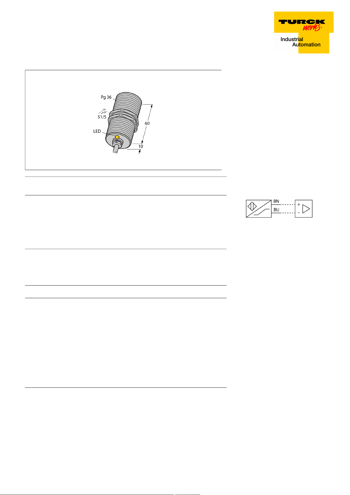
Inductive sensor
BI20-G47-Y1X
■ ATEX category II 2 G, Ex zone 1
■ ATEX category II 1 D, Ex zone 20
■ SIL2 (Low Demand Mode) acc. to IEC
61508, PL c acc. to ISO 13849-1 at HFT0
■ SIL3 (All Demand Mode) acc. to IEC
61508, PL e acc. to ISO 13849-1 with redundant configuration HFT1
■ Threaded barrel, PG36
■ Chrome-plated brass
■ DC 2-wire, nom. 8.2 VDC
■ Output acc. to DIN EN 60947-5-6 (NA-
MUR)
■ Cable connection
Type designation BI20-G47-Y1X
Ident-No. 10202
Rated switching distance Sn 20 mm
Mounting conditions Flush
Secured operating distance
Correction factors St37 = 1; Al = 0.3; stainless steel = 0.7; Ms = 0.4
Repeat accuracy
Temperature drift
Hysteresis 1…10 %
Ambient temperature -25…+70 °C
Output function 2-wire, NAMUR
Switching frequency 0.2 kHz
Voltage Nom. 8.2 VDC
Non-actuated current consumption
Actuated current consumption
Approval acc. to KEMA 02 ATEX 1090X
Design Threaded barrel,G47
Dimensions 70 mm
Housing material Metal, CuZn, Chrome-plated
Active area material Plastic, PA12-GF30
End cap Plastic, PA66-GF25
Max. tightening torque housing nut 90 Nm
Electrical connection Cables
Cable quality 5.2mm, Blue, LifYY, PVC, 2
Cable cross section
Vibration resistance 55 Hz (1 mm)
Shock resistance 30 g (11 ms)
Protection class IP67
MTTF 6198 years acc. to SN 29500 (Ed. 99) 40 °C
Packaging unit 1
ð (0,81 x Sn) mm
ð 2 % of full scale
ð ± 10 %
ï 2.1 mA
ð 1.2 mA
2 x 0.34 mm
2
Wiring Diagram
Functional principle
Inductive sensors detect metal objects contactless and wear-free. For this, they use a
high-frequency electromagnetic AC field that
interacts with the target. Inductive sensors
generate this field via an RLC circuit with a
ferrite coil.
Switching state LED,Yellow
Edition • 2018-04-27T17:08:34+02:00
1 / 4 TURCK Inc.
Inductive sensor
BI20-G47-Y1X
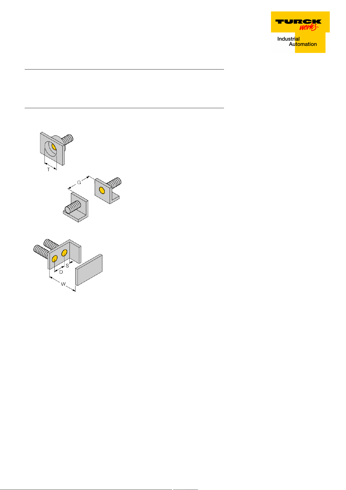
Distance D 2 x B
Distance W 3 x Sn
Distance T 3 x B
Distance S 1.5 x B
Distance G 6 x Sn
Diameter active area B Ø 47 mm
Edition • 2018-04-27T17:08:34+02:00
2 / 4 TURCK Inc.
 Loading...